Table of Contents

Related Manuals for Kanomax Gasmaster 2750


Summary of Contents for Kanomax Gasmaster 2750
- Page 1 Kanomax Gasmaster 2710 (V1.X), & 2750 (V1.X) User Guide V 1.0 Kanomax USA, Inc. 219 US Highway 206 Andover, NJ 07821 Phone: 973-786-6386 / Fax: 973-786-7586 Web: www.kanomax-usa.com E-mail: info@kanomax-usa.com Kanomax Gasmaster User Guide...
-
Page 2: Table Of Contents
Tables ..........................17 4.2.5. Data Analysis ........................ 17 4.3. Advanced Data Management....................18 External Control Wiring (Model 2750) ..................18 5.1. Wiring for Alarm........................19 5.2. Wiring for Control ........................19 Page | 2 Kanomax Gasmaster User Guide MRK-D-0002 V3... - Page 3 10.1. Disposal / Recycling ......................35 11. Appendix ............................36 11.1. Copyright ........................... 36 11.2. Software License ....................... 36 11.3. Terms and Conditions ....................... 36 11.4. Statements of Compliance ....................36 Page | 3 Kanomax Gasmaster User Guide MRK-D-0002 V3...
-
Page 4: Monitor Components
User manual Note 1: The data logging software for the Model 2750 can be found at: http://www.kanomax-usa.com/iaq/gasmaster/gasmaster.html Please check that all these components have been supplied and contact your distributor or Kanomax info@kanomax-usa.com if any of the components are missing. -
Page 5: Installation
A fully charged battery will run for approximately 4-6 hours depending on the sensor head being used. With the adaptor plugged in and unit turned on allow 15 hours for the battery to fully Page | 5 Kanomax Gasmaster User Guide MRK-D-0002 V3... -
Page 6: Charging Lithium Polymer Batteries
LED will remain on, even if the battery is fully changed. 2.1.5. Safety Information • Do not use the battery pack for any other purpose than operating the Kanomax Gasmaster • Do not disassemble or deface the batteries as this may cause burns •... -
Page 7: Sensor Heads
Note: This message will only apply for O3 Low/Ultra Low sensor heads. “S.F.” – When there is more than one sensor connected, S.F. will show for a sensor failure condition. Page | 7 Kanomax Gasmaster User Guide MRK-D-0002 V3... -
Page 8: Optional Temperature And Relative Humidity Sensor
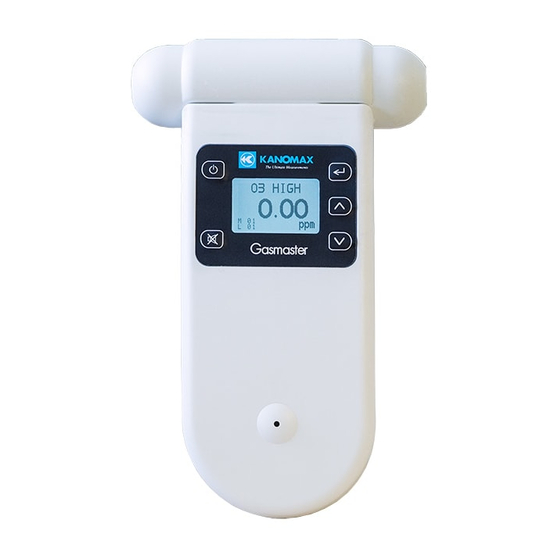
The following instructions detail the operation and set up of the monitor: 3.1. Model 2710 Display Power button / Enter Scroll button 3.2. Model 2750 Display Power button Enter Scroll up Alarm mute Scroll down Page | 8 Kanomax Gasmaster User Guide MRK-D-0002 V3... -
Page 9: Powering On And Off
To turn the monitor on: Press and hold the power button until the screen activates. The monitor will turn on and the display will show KANOMAX GASMASTER and the Model Number and Firmware Version. If the monitor is configured for use with a Lithium battery, it will also say “Lithium Battery”. -
Page 10: Units
• When the “MAX MIN AV” cycle is initiated, the display should read as seen below: O3 UL O3 UL TEMP RH 0.010 0.010 0.005 0.005 0.024 MAX 0.024 0.015 0.015 Page | 10 Kanomax Gasmaster User Guide MRK-D-0002 V3... -
Page 11: Calibration
The monitor ID can be found under “MONITOR SETUP”, scroll down in the monitor set up menu and select “MONITOR ID” • Each monitor can be numbered to identify them quickly when more than one is in use Page | 11 Kanomax Gasmaster User Guide MRK-D-0002 V3... -
Page 12: Output Sensor (Model 2750)
Note: The alarm can be muted by pressing the mute button on the display screen. However, this is only a temporary mute and will only mute the alarm during that specific alarm condition. Page | 12 Kanomax Gasmaster User Guide MRK-D-0002 V3... -
Page 13: Control Points (Model 2750)
The option to clear the log will then display on the screen. • Press the “scroll up” button to select either YES or NO and press “enter” to confirm the selection. Page | 13 Kanomax Gasmaster User Guide MRK-D-0002 V3... -
Page 14: Kanomax Gasmaster Monitor Software (Model 2750)
A filling triangle indicates that some data is stored in the memory. The triangle will fill up in 10% increments. • A full triangle indicates that the memory is full and needs downloading to the PC. Kanomax Gasmaster Software (Model 2750) 4.1. Set Up Computer Requirements •... -
Page 15: Connect
4.1.1. Connect 1. Connect the Model 2750 monitor to a computer using the cable supplied and turn on 2. Launch the Kanomax Gasmaster PC software and click on the toolbar to search for the monitor. The unit will be detected automatically and connect 3. -
Page 16: Downloading Logged Data From Model 2750
The data will be tagged with whatever the monitor ID is at the time of download. Conversely, the location ID is logged on each record in the monitor. Page | 16 Kanomax Gasmaster User Guide MRK-D-0002 V3... -
Page 17: Tables
The summary data files can be exported to programs such as MS Excel by clicking the “Export” button. To delete the summary data click the “Delete” button. This will not delete the individual data points from the database, only the daily summary data. Page | 17 Kanomax Gasmaster User Guide MRK-D-0002 V3... -
Page 18: Advanced Data Management
The pin numbers for the external output connector are numbered from 1 to 6. Pin 1 is the closest pin to the power jack. The pin designations are as follows: 1. 12 V DC 2. Analogue output 0-5 V 3. Control 4. High alarm 5. Low alarm 6. Ground Page | 18 Kanomax Gasmaster User Guide MRK-D-0002 V3... -
Page 19: Wiring For Alarm
The RJ12 connector offers two possibilities for wiring, either a switch to GND or a 12V output. If the 12V output is used, the power for the relay coil is supplied by the Kanomax AC/DC adaptor. In this case, ensure that the relay coil does not draw more than 150mA and that a protection diode is inserted across the relay coil. -
Page 20: Wiring The 0-5 V Analogue Output
Note: The ultra-low ozone sensor is a special case – 1.5V represents 0.150ppm ozone in this case. Note: Wire between pins 2 & 6 See Section 7.1 for output status conditions. Page | 20 Kanomax Gasmaster User Guide MRK-D-0002 V3... -
Page 21: Calibration Of Sensor Heads
1. Charge R42 Calibration Gas Accessory with 5g of water with water syringe via water inlet. 2. Fit cylinder and regulator to R42 gas inlet via tubing and Luer attachment. 3. Place warmed up Kanomax sensor head in R42 outlet as shown below. The Kanomax sensor head is now ready for zero or span calibration. -
Page 22: Zero Calibration
Span calibration is only available on the Model 2750. It provides an option to adjust the GAIN of Kanomax sensor heads. There are no optimum span concentrations for calibrating Kanomax sensor heads. There are however a few considerations which can guide the decision as to which span concentration is most appropriate. - Page 23 PID (Isobutylene) 0-1000 PTFE (Teflon) * The R42 cannot be used for the calibration of NH3 due a material incompatibility. Contact Kanomax for advice on calibrating NH3 sensor heads. ** Contact Kanomax for information regarding PERC calibration Page | 23...
-
Page 24: Procedure
3. Measure the gas concentration on the monitor screen and wait for it to stabilise (10 minutes). 4. If the Kanomax sensor head requires a span adjustment then enter the CALIBRATE menu by pressing the “mute” and “scroll down” buttons simultaneously for 2 seconds. Then select SPAN CAL and change the GAIN using the scroll buttons. -
Page 25: High Pressure Leak Or Failure Of Pressure Regulator
(spark or flame) is present. The LELs for the gases used for calibrating Kanomax sensor heads are all significantly above the calibration span points so this risk is low. It is important however that the LEL be known for the gas being employed and that suitable precautions be taken to further minimize the risk from explosive combustion such as performing the calibration in a fume hood. - Page 26 Permissible exposure limit (usually based upon a time weighted 8 hour average STEL: Short - term exposure limit ( 1 hour average) LEL: Lower explosion limit Source: http://www.cdc.gov/niosh/idlh/intridl4.html 21/06/2013 (always check for latest information) Page | 26 Kanomax Gasmaster User Guide MRK-D-0002 V3...
-
Page 27: Specifications
EMF suppression diode must be fitted across the load. Kanomax accepts no responsibility for damage to this product or any other issues arising from the non-compliance with the above directives. Failure to implement these directives will invalidate the warranty on this product. -
Page 28: Diagrams
7.1. Diagrams Page | 28 Kanomax Gasmaster User Guide MRK-D-0002 V3... -
Page 29: Optional Extra: Handheld Enclosure
Temp/RH sensor Data logging Power Connection connection connection 7.2.2. Replacing the Sensor Head 1. Undo the four lid screws at each corner using a flat headed screw driver and remove the lid. Page | 29 Kanomax Gasmaster User Guide MRK-D-0002 V3... -
Page 30: Removing The Monitor
5. Carefully disconnect the monitor from the sensor head and remove from the enclosure. 6. Reverse the process to reconnect the monitor back onto the battery cover. Troubleshooting Page | 30 Kanomax Gasmaster User Guide MRK-D-0002 V3... - Page 31 Clean sensor inlet filter and mesh reading in the presence of sensor gas Sensor fan failed Replace sensor Interfering gas present Move sensor to clean air and check reading upon exposure to known gas Page | 31 Kanomax Gasmaster User Guide MRK-D-0002 V3...
-
Page 32: Sensor Failure
(MODEL 2750 only) Clock setting incorrect Synchronise clock with PC. If this does not work then the Monitor clock battery may be flat. Return monitor to Kanomax for battery replacement. 8.1. Sensor Failure The handheld monitors have inbuilt diagnostics to detect sensor faults. If the sensor fails it can be... -
Page 33: Technical Support
The failed sensor can be sent back to Kanomax for refurbishment or disposal. Monitor status conditions are as follows: High 0-5V Control Low Alarm Data Alarm Fault Output Output Output... -
Page 34: Guidelines On How To Measure Ozone
Guidelines on How to Measure Ozone The following information is presented to help users operate their Kanomax Gasmaster with an ozone sensor installed in the most effective and efficient manner. General • Ozone is heavier than air and tends to sink. Thus detection of leaks from ozone generating equipment should be performed at the most appropriate position. -
Page 35: Care And Maintenance
Care and Maintenance Your Kanomax Gasmaster is a product of superior design and quality and should be treated with care. When using your Kanomax Gasmaster: • Keep it and all its parts and accessories out of the reach of small children. -
Page 36: Appendix
Kanomax reserves the right to revise this document or withdraw it at any time without prior notice. The availability of particular products may vary by region. Please check with the Kanomax dealer nearest to you. - Page 37 The Kanomax Gasmaster Models 2710 & 2750 Monitors and Remote Adaptor Kit comply with Part 15 of the FCC Rules. Operation is subject to the following two conditions: (1) these devices may not cause harmful interference, and (2) these devices must accept any interference received, including interference that may cause undesired operation.
Need help?
Do you have a question about the Gasmaster 2750 and is the answer not in the manual?
Questions and answers