Table of Contents
Advertisement
Quick Links
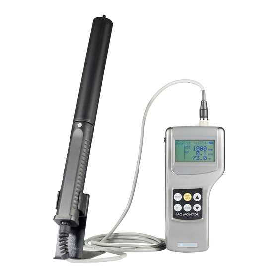
List of Components
■ Standard
Item
Main Body
Probe
Carrying Case
Probe Stand
Gas Calibration Cap
Tube
Operation Manual
Manganese AA Batteries
Software CD-ROM
RS232C Cable
■ Options
Item
ZERO Gas
CO Span Gas
CO
Span Gas
2
Gas Valve
Spare Probe
Analog Output
AC Adapter
Printer
(Recommended)
Printer Cable
Model
Qty.
2212-00
1
2212-01
1
CO, CO
2211-02
1
2211-03
1
Used to hold and stabilize a probe
2211-04
1
Used for gas calibration
Used to connect the above gas calibration cap to a
-
1
calibration gas cylinder
-
1
-
6
2212-41
1
Data Acquisition Software (for Windows)
6000-02
1
Used to connect the instrument and PC
Model
2211-05
Zero Point Calibration for CO and CO
2211-06
CO Span Calibration (Approx. 35ppm)
2211-07
CO
2211-08
Valve for the gas cylinders listed above
2212-01
Spare Probe
2212-09
Analog Output Terminal
6113-02
Power Supply
DPU-S245
For printing out calculation results
Printer cable for connecting the instrument with
6000-03
the printer.
Features
-
, Temperature, Humidity Sensor
2
-
-
Features
Span Calibration (Approx. 1000ppm)
2
2
Advertisement
Table of Contents

Subscribe to Our Youtube Channel
Related Manuals for Kanomax 2212


Summary of Contents for Kanomax 2212
- Page 1 List of Components ■ Standard Item Model Qty. Features - Main Body 2212-00 Probe 2212-01 CO, CO , Temperature, Humidity Sensor Carrying Case 2211-02 Probe Stand 2211-03 Used to hold and stabilize a probe Gas Calibration Cap 2211-04 Used for gas calibration Used to connect the above gas calibration cap to a -...
-
Page 2: Table Of Contents
Table of Contents 1. Part Names and Functions ................ 1 1.1 Main Body......................1 1.2 Operation Panel ....................2 1.3 Probe ........................3 2. Getting Started ................... 4 2.1 Installing Batteries ....................4 2.2 Connecting Probe ....................5 2.3 Disconnecting Probe .................... 5 2.4 Turning ON/OFF the Power ................ - Page 3 7. Other Settings ................... 29 7.1 Changing Date and Time ................... 29 7.2 Changing Measurement Unit and Baud Rate ............. 30 7.3 Deleting Data ..................... 31 7.3.1 To Delete Certain Pages of Data ................31 7.3.2 To Delete All Data ..................... 32 7.4 Contrast Adjustment ..................
-
Page 4: Part Names And Functions
1. Part Names and Functions 1. Part Names and Functions Approx. 88 1.1 Main Body Unit: mm Probe Socket Display Analog output Terminal (Optional) RS232C Terminal DC Input Terminal Power Switch I : ON O: OFF Operation Panel IAQ MONITOR Battery Compartment Approx. -
Page 5: Operation Panel
1. Part Names and Functions 1.2 Operation Panel MENU KEY MENU KEY Press once to access the MENU screen to select the desired feature. Press once to access the MENU screen to select the desired feature. * If pressing this key while measuring or configuring the settings, whatever the operation being conducted * If pressing this key while measuring or configuring the settings, whatever the operation being conducted will be cancelled and you will go back to the MENU screen. -
Page 6: Probe
1. Part Names and Functions 1.3 Probe Approx.φ25 Unit: mm CO Sensor Temperature Sensor Humidity Sensor sensor Approx.φ15 Approx.φ32 Probe Number L=Approx.2000... -
Page 7: Getting Started
2. Getting Started 2. Getting Started 2.1 Installing Batteries Backside of the instrument 1. Press down the battery cover with your finger as shown left. 2. Slide the cover toward the bottom of the instrument. 3. Lift the cover away from the instrument. Types of batteries that can be used - Manganese (R6), AA batteries - Alkaline (LR6), AA batteries... -
Page 8: Connecting Probe
2. Getting Started 2.2 Connecting Probe CAUTION * Make sure that the power is OFF when connecting or disconnecting the probe. 1. Put the probe’s connector on the main body’s probe socket. 2. Push the connector in until you hear a click. CAUTION * DO NOT squeeze the probe into the main body or twist the probe when it is attached, as it may cause a serious damage... -
Page 9: Turning On/Off The Power
The power switch for turning ON/OFF the instrument is located at the side of the instrument. When powered up after a probe is connected, the KANOMAX logo, its model name and software version will be displayed for a few seconds before the measurement mode screen shows up. -
Page 10: Precautions For Measurement
2. Getting Started 2.5 Precautions for Measurement 2.5.1 CO and CO Measurement Precautions Air diffusion condition (flow condition) affects the response time of CO and CO sensor. In order to obtain an accurate measurement result, perform a measurement in the place which has the flow of air as much as possible. ... -
Page 11: Temperature Measurement Precautions
2. Getting Started <Atmospheric Pressure Correction> When atmospheric pressure at a measuring site is abnormal (such as at high altitude), follow steps below to set atmospheric pressure (default setting: 1013hPa). Since the change of weather does not significantly affect the atmospheric pressure as long as the measuring site is same (excluding the case of typhoon), once you set atmospheric pressure, you do not need to set it every time. -
Page 12: Measurement (Normal Mode)
3. Measurement 3. Measurement (NORMAL MODE) This is the mode that you will see when you turn on the instrument. In this mode you cannot store any data. Any displayed readings are updated every 1 second. To move to NORMAL Mode from other measurement mode, press key to bring up the MENU screen, select “1. -
Page 13: Hold The Reading
3. Measurement 3.2 Hold the Reading Display Procedure When the NORMAL (Measurement) mode screen is displayed, press key (also available on Humidity measurement mode). “HOLD” indicator appears on the left side of the display to indicate that the reading shown is kept on hold on the display. Press key again to recover from the HOLD mode. -
Page 14: Measuring Max, Avg And Min Value
4. Measuring MAX, AVG and MIN Value 4. Measuring MAX, AVG and MIN Value (CALUCULATION MODE) In Calculation Mode measurement data is stored and maximum, mean and minimum values will be calculated. TRIAL(2) ………………… TRIAL(N) TRIAL(1) ● Average (AVG) AVG=ΣTRIAL(N)/N ●... - Page 15 4. Measuring MAX, AVG and MIN Value Display Procedure <To set CALCULATION MODE> key to select “1. MODE”, and press key. key to select either “AVERAGE” or “INSTANT” and press key. <To set SAMPLING TIME> key to select “2. SAMPLING TIME”, and press key.
- Page 16 4. Measuring MAX, AVG and MIN Value Display Procedure <While Measuring> Press key to stop measuring. (If “YES” is selected for “4. DATA STORAGE ?”, the measured data will be stored.) You can also stop measuring by pressing key. However, any measured data will not be stored.
-
Page 17: Measuring Percent Outdoor Air
5. Measuring Percent Outdoor Air 5. Measuring Percent Outdoor Air (%OA MODE) %OA MODE is a measurement mode to calculate Percent Outdoor Air either with temperature or CO The calculation is based on below formula: Outdoor Air (O_A) %OA=(R_A – S_A) / (R_A – O_A) × 100 * %OA:... - Page 18 5. Measuring Percent Outdoor Air Display Procedure Press key to bring up the MENU screen. key to select “3. %OA”, and press key. <To set SAMPLING TIME > key to select “1.MODE”, and press key. key to select “TMP.” or “CO2”, and press key.
- Page 19 5. Measuring Percent Outdoor Air Display Procedure <DATA STORAGE> key to select “4.DATA STORAGE ?”, and press key. key to select “YES” or “NO” for data storage, and press key. <To save the settings> key to select “5.SET TO START”, and press key.
- Page 20 5. Measuring Percent Outdoor Air Display Procedure <Calculation Result> After all the measurements are finished, the calculation result will be displayed. Press key to display average values of Return Air (R_A), Supply Air (S_A), and Outdoor Air (O_A) at each point. Press key to return to the MENU screen.
-
Page 21: Data Output
6. Data Output 6. Data Output 6.1 Stored Data Item The measurement data that can be stored in the instrument in the each measurement mode and measurement screen is listed in the table below. Measurement Mode Measurement Display Stored Parameters CALCULATION Mode , CO, Temperature, Humidity All measurement display... - Page 22 6. Data Output Display Procedure CALCULATION <Measurement data display screen> Measurement data of the specified page will be displayed. key to scroll the data. When a measurement is performed in the CALCULATION mode, press key to switch to display between Temperature and Humidity. Data No.
-
Page 23: Printing Out Measurement Data
6. Data Output 6.3 Printing out Measurement Data RS232C Terminal (Note 1) To print out stored measurement data, a printer cable must be connected to the RS232C terminal located at the side of the instrument. :Although you can see both RS232c mark ( Note1 ) and USB mark ( near the terminal, only RS232c is available for this instrument. -
Page 24: Printing From Calculation Mode
6. Data Output 6.3.3 Printing from CALCULATION mode Display Procedure After the calculation measurement is completed and the calculation result is shown, press key to print out the measurement result. 6.3.4 Printing from %OA (Percent Outdoor Air) mode Display Procedure After %OA measurement is completed and the calculation result is shown, press key to print out the measurement result. -
Page 25: Printing Out Stored Data
6. Data Output 6.3.5 Printing out Stored Data Display Procedure Press key to bring up the MENU screen. key to select “4.DATA OUTPUT”, and press key. key to select “2.PRINTER”, and press key. key to select the page that you want to display, and press key. - Page 26 6. Data Output Example of Printout <CALCULATION Mode> <%OA Mode> PAGE SET PAGE SET PAGE :011 PAGE :002 Measurement MODE : CALCULATION(I) MODE :%OA(TMP.) Condition DATE :2004/06/21 DATE :2004/06/19 (These items are printed out TIME :16:23:08 TIME :13:35:23 all the time.) ATM.
-
Page 27: Digital Output
6. Data Output RS232C 6.4 Digital Output Terminal (Note 1) 6.4.1 Preparation for Digital Output For digital-outputting stored measurement data, RS232C cable must be connected to the RS232C terminal located at the side of the instrument. :Although you can see both RS232c mark ( Note1 ) and USB mark ( near the terminal, only RS232c is available for this instrument. -
Page 28: Entering Commands From Pc To Output Data
6. Data Output 6.5 Entering Commands from PC to Output Data As for connecting your PC to the instrument, Command Function refer to “6.4.1 Preparation for Digital Output” (Page 24). To set how many data to read D**** Receive Interrupt To output measurement condition To output measurement unit -----Icon and its meaning-----... -
Page 29: Transmission Of Stored Data (Data Stored In Memory)
6. Data Output 6.5.2 Transmission of Stored Data (data stored in memory) Display Procedure <To set humidity related data output> Enter “F ”. After the command is received, “AF” will be returned and humidity related data such as DT, WB, AH, and HR will be added in the subsequent data output. -
Page 30: Analog Output (Optional)
6. Data Output 6.6 Analog Output (Optional) 1. Data Update Interval …… 1 second 2. Load Impedance………… 5KΩ and above Analog Output 3. Output Voltage……………DC 0-1V Terminal As For the analog output, you can select one output range from the table below. - Page 31 6. Data Output Display Procedure Press key to bring up the MENU screen. key to select “6.UTILITY”, and press key. key to select “3.ANALOG OUTPUT”, and press key. <To select measurement item to output > key to Select “1.OUTPUT SELECT”, and press key.
-
Page 32: Other Settings
7. Other Settings 7. Other Settings 7.1 Changing Date and Time Display Procedure Press key to bring up the MENU screen. key to select “6. UTILITY”, and press key. key to select “1. TIME ADJUST”, and press key. key to select the item that you want to change (“1.STYLE”, “2.DATE”... -
Page 33: Changing Measurement Unit And Baud Rate
7. Other Settings 7.2 Changing Measurement Unit and Baud Rate <Unit Conversion Table> Temperature F) =1.8 x T( C) + 32 )=6.24×10 ) Absolute Humidity 1(g/m (lb/ft Humidity Ratio 1(g/kg)=9.9999×10 (lb/lb) Display Procedure Press key to bring up the MENU screen. key to select “6. -
Page 34: Deleting Data
7. Other Settings 7.3 Deleting Data 7.3.1 To Delete Certain Pages of Data When data is deleted partially, data is deleted per page. One measurement taken in CALCULATION MODE or % OUTDOOR AIR (%OA) MODE is stored in one page. Display Procedure Press... -
Page 35: To Delete All Data
7. Other Settings 7.3.2 To Delete All Data Display Procedure Press key to bring up the MENU screen. key to select “5. DATA CLEAR, and press key. key to select “2. ALL CLEAR” (to delete all), and press key. ……The first page to be deleted ……The last page to be deleted ……Delete partially (YES or NO) ……Delete all (YES or NO) -
Page 36: Contrast Adjustment
7. Other Settings 7.4 Contrast Adjustment There is a contrast adjuster inside the battery cover located at the rear side of the main body. The contrast of the screen can be adjusted by using a flat-blade precision screwdriver (0.9 ~ 1.5mm). As described in the picture below, turn it clockwise to darken and vice versa. -
Page 37: Calibrating Co/Co
It is recommended to calibrate the IAQ Monitor’s CO/CO2 measurement every 2-3 months to ensure accurate readings. In addition, it is still recommended to send your IAQ monitor to KANOMAX for annual calibration. * It is recommended to exchange the CO sensor annually and it is a consumable. -
Page 38: Calibration Procedure - Zero Calibration
8. Calibrating CO/CO Sensor 8.2 Calibration Procedure – ZERO Calibration Display Procedure Connect a ZERO gas cylinder to the IAQ Monitor as described in the previous page. Press key to bring up the MENU screen. key to select “7. CALIBRATION”, and press key. - Page 39 8. Calibrating CO/CO Sensor Fully open the regulator valve to emit gas. Press key to start calibration. Ready to start calibration: Countdown initial value is displayed here. When selecting CO only, the countdown initial value is 90 seconds. When selecting CO2 only, it is 120 seconds.
- Page 40 8. Calibrating CO/CO Sensor If the calibration result is NG Calibration will be terminated. Reading after calibration It shows that calibration is ended. It shows the result of calibration (when calibration fails.) Operation When “END” is displayed, close the valve of the regulator to turn off the gas.
-
Page 41: Calibration Procedure - Span Calibration
8. Calibrating CO/CO Sensor 8.3 Calibration Procedure – SPAN Calibration Display Procedure Connect a Span gas cylinder to the IAQ Monitor as described in the previous page. Press key to bring up the MENU screen. key to select “7.CALIBRATION”, and press key. - Page 42 8. Calibrating CO/CO Sensor Press key to start calibration. It shows that gas is emitted and it is waiting for key to be entered. It shows countdown initial value. (unit: second) (CO Calibration: 90sec / CO2 Calibration: 120sec) Operation Replace the ZERO gas cylinder that is connected to the instrument with a SPAN gas cylinder.
- Page 43 8. Calibrating CO/CO Sensor If the calibration result is NG Calibration will be terminated. Reading after calibration It shows that calibration is ended. It shows a calibration result. … … Operation When “END” is displayed, close the valve of the regulator to turn 1.
-
Page 44: Specifications
9. Specifications 9. Specifications Product IAQ Monitor Model 2212 Measuring Object Clean Air flow Measuring Method Electrochemical Measuring Range 0.1~500ppm Resolution 0.1~99.9ppm: 0.1ppm,100-500ppm: 1ppm Accuracy ±3% of the reading or ±3ppm; greater value is applied. (@20 C (within -20~40 Temperature Dependence ±0.125 %FS/ C: standard is 20 C)... -
Page 45: Calculation Result: Dt, Wb, Ah And Hr
10. Calculation Result: DT, WB, AH and HR 10. Calculation Result: DT, WB, AH and HR 10.1 What is DT? DT -- Dew Point Temperature Warmer air contains much water vapor. As the air gets cooled, it reaches saturation at a certain temperature (Relative Humidity: 100%). -
Page 46: What Is Ah
10. Calculation Result: DT, WB, AH and HR Ln (e )=-6096.9385×T +21.2409642-2.711193×(10 )×T +1.673952×(10 ) × T +2.433502×ln(T A= e f’(tw)=4030.183/((235+tw) )×A+P/2/755 tw1=tw-(A-P×(t-tw)/2/755-E×U/100)/f’(tw) tw: Wet-bulb temperature ( : Saturated Water Vapor Pressure at tw (Pa) : Absolute Temperature (k)=(tw+273.15) P: Barometric Pressure (Pa) E: Saturated Water Vapor Pressure at t (Pa) U: Relative Humidity T: Dry-bulb Temperature (... -
Page 47: Troubleshooting
11. Troubleshooting 11. Troubleshooting 11.1 Battery Check Refer To Symptom Possible Cause(s) / Solution(s) (Page No.) Display does not appear when The battery is exhausted. 4, 6 → power is turned ON. Turn OFF the power and replace the batteries. Nothing appears on the display The contrast of the display is not adjusted properly. -
Page 48: Digital Output Check
11. Troubleshooting Printer may not be compatible (DPU-H245 and DPU-201GS are recommended). → Check your printer type. Printer may not be connected in the right order. → After connecting the printer, turn on the instrument first, and then turn on the printer. Unable to printout the display. -
Page 49: Warranty And After-Sales Service
12. Warranty and After-sales Service Kanomax Limited Warranty The limited warranty set below is given by KANOMAX with respect to the KANOMAX brand IAQ Monitor, its attachment parts including Probe and other accessories (hereafter referred to as “PRODUCT”) that you have purchased. -
Page 50: After Service
Whenever the PRODUCT is malfunctioning, please check with “Troubleshooting” to find possible cause first. Repair parts are retained for a minimum period of five (5) years after production cessation of the PRODUCT. This storage period of repair parts is considered as the period during which KANOMAX can provide repair service. -
Page 51: Contact Information
Copyright © Kanomax Japan Inc. All rights reserved. 2014 No copying, distribution, publication, modification, or incorporation of this document, in whole or part, is permitted for commercial purposes without the express written permission of Kanomax. The contents of this document may be changed without prior notice. 05001/14.10... - Page 52 13. Contact Information...
Need help?
Do you have a question about the 2212 and is the answer not in the manual?
Questions and answers