Table of Contents
Advertisement
Quick Links
Advertisement
Table of Contents

Related Manuals for Kanomax Anemomaster 6036


Summary of Contents for Kanomax Anemomaster 6036
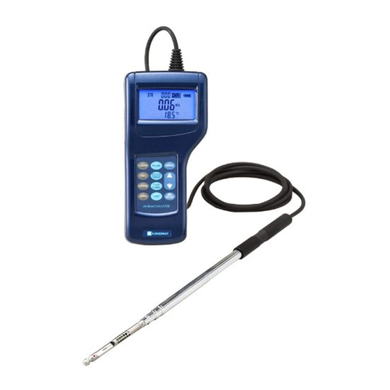
- Page 2 List of Components Standard ■ Items MODEL Functions 6035-00 With analog 6035-A0 output function Straight Probe ANEMOMASTER With pressure To measure air 6035-B0 Standard sensor velocity, air temp, and Main Body With analog volumetric flow rate. output function 6035-C0 and pressure sensor 6036-00 these...
-
Page 3: Important Safety Information
Important Safety Information The symbols for the warnings used in this manual are defined below. Classifications Danger: To Prevent Serious Injury or Death Warnings in this classification indicate danger that may result in serious injury or death if not observed. Caution: To Prevent Damage to the Product Warnings in this classification indicate risks of damage to the product that may void the product warranty if not observed. - Page 4 Danger Never bring the probe close to a flammable gas atmosphere. The heated sensor may cause a fire or explosion. Forbidden Never touch the sensor. The sensor is heated during operation. Touching the heated sensor may cause burns, and may also damage the sensor itself. Don’t touch Hot surface Do not disassemble or heat the batteries, or put them into a...
- Page 5 Do not use or leave the instrument in a high temperature, high humidity or dusty environment. Do not leave this instrument under direct sunlight for a prolonged period. Forbidden The instrument may not function properly out of the specified operating conditions. Do not subject the instrument or the probe to strong impacts.
- Page 6 Do not move the main unit and the probe from a cold place to a warm place quickly. It will cause dew condensation. Even when used in an environment within the specified operating Forbidden temperature and humidity, a sudden temperature change may cause condensation.
-
Page 7: Table Of Contents
Influence of Air Composition ............30 § 11 Probe Directivity (Air Velocity) ..........31 § 12 Troubleshooting ..............32 Various Status Displays ..............33 § 13 Warranty and After Service ..........34 Kanomax Limited Warranty ............. 34 § 14 Contact Information ............35... -
Page 8: Part Names And Functions
§ 1 Part Names and Functions Overview Unit: mm Probe Approx.Φ6 Main Body Approx.Φ14... -
Page 9: Main Body
Main Body Unit: mm Approx.88 Analog Output Analog output is ■ Terminal available on MODEL6535-A0 /-C0 and Serial Communication Probe Socket MODEL6536-A0 Terminal /-C0 DC Input Terminal Power Switch I: ON LCD Display O: OFF Touch Panel Battery Compartment Part Names and Functions... -
Page 10: Touch Panel
Touch Panel MODE Key: SHAPE Key: CLEAR Key: To change To select duct type To clear stored measurement mode. and size for data. measuring volumetric CALC Key: flow rate. To obtain ▲▼ Key: average, max, 1. To move the and min. cursor for selecting an item STORE Key:... -
Page 11: Probe
Probe <Straight Probe (MODEL6035) > Direction Mark 風向点 Air Velocity Sensor 風速素子 Temp. Sensor and 温度素子・温度補償素子 Temp. Compensation Sensor Approx.Φ6mm <Articulating Probe (MODEL6036)> -How to extend the Articulating Probe- Hold the upper part Caution: 1 of the probe, and Do not excessively unscrew 2. -
Page 12: Getting Started
§ 2 Getting Started Installing Batteries Backside of the body Press down on the battery cover with your finger as shown left. Slide the cover toward the bottom of the instrument until it stops, Lift the cover away from the body. -
Page 13: Turning On/Off The Power
Turning ON/OFF the Power The power switch to turn the power ON/OFF is located at the side of the instrument. When powered up, the LCD test screen will be displayed before it switches to the Air Velocity / Air Temperature measurement screen in approx. - Page 14 Battery Level Indicator Check the “Battery Level Indicator” to confirm the remaining battery level. The battery consumption rate largely depends on the measured air velocity. When the batteries need to be replaced (or recharged), the indicator will start blinking. When using a charging battery, the battery level may be ...
-
Page 15: Precautions For Measurements
Precautions for Measurements Air Velocity Measurement Precautions Direction Mark ● The probe has its own directivity characteristics. Make sure that the direction mark is facing into the airflow (for details of the directivity characteristics, refer to “Probe Directivity (Air Velocity)” on P.31). If you are not Air Flow sure of the airflow direction, slowly rotate the probe and select the point where you get the... - Page 16 Press key to enter the setting screen. <Registering a Rectangular Duct> Select with the keys, and press the key. <Registering a Circular Duct> Select with keys, and press the key. <Entering the Dimension of a Rectangular Duct> Set the height (H) with keys and press the key.
-
Page 17: Measurement
§ 3 Measurement When the instrument is turned on, the LCD test screen will be displayed for approx. 2 seconds. The test screen will then switch to the Air Velocity / Air Temperature measurement screen. The display is updated every 1 second. Changing the Measurement Mode To change the measurement mode, press the key while each... -
Page 18: Setting The Time Constant
Setting the Time Constant When there is rapid change in the measurement data, the readings may become difficult to read. In such case, the speed of updating the readings can be reduced by changing the time constant setting. Time Constant determines the time span of the moving average. *Time constant can When a larger (longer) time constant is selected, the readings will be set only for Air... -
Page 19: Data Storage And Statistical Calculation
§ 4 Data Storage and Statistical Calculation Storing Measured Data Measured data can be stored in the built-in memory of the Data storage ■ instrument. The instrument can hold up to 1500 data records. When function is only storing the measured data, average, maximum and minimum available on values will be calculated for the data group to be stored. - Page 20 ●Data Storage and Statistical Calculation Press the key to execute the statistical calculation (Average, Maximum and Minimum) for the group of data records stored in the temporary memory. Display will switch in the sequence shown as follows (AVG MAXMIN) as you press the key.
-
Page 21: Viewing And Deleting Stored Data
Viewing and Deleting Stored Data The average, maximum and minimum value of the stored data can The function ■ be viewed on the display and deleted. of viewing and Data viewing and deleting procedure will be described below by deleting stored data taking an example of an operation in the “Air Velocity / Air is available on... -
Page 22: Setting The Measurement Unit And Baud Rate
§ 5 Setting the Measurement Unit and Baud Rate List of Measurement Units: <Unit Conversion Table> ●Air velocity: m/s, FPM Air Velocity: 1m/s=196FPM ●Volumetric flow rate: Air Temp: T ( F)=1.8×T( )+32 °C /h, ft /min, m /min Volumetric Flow: 1 m /h=35.32 ft ●Air temperature: °C, °F Length: 1inch=25.4 mm... -
Page 23: Data Output
§ 6 Data Output Printing Out the Measurement Data (MODEL6036) Print function is ■ To print out the stored measurement Serial only available data, an optional printer and printer Communication Terminal cable are required. The printer cable MODEL6036 must be connected to the serial communication terminal located on the side of the instrument. - Page 24 Printout Examples (Measurement Mode) Measurement Mode Air Velocity / Volumetric Flow / Pressure/Air Air Temperature Air Temperature Temperature ●EXAMPLE ●EXAMPLE ●EXAMPLE (Rectangular duct) Duct Shape R Size 2550*2550mm FlowRate 407.3 m3/h 0.15m/s Press 1.03kPa Temp 22.5 Temp 21.8°C Temp 20.1°C ●EXAMPLE (Circular duct) Duct Shape C Size 2550mm...
- Page 25 Printout Examples (Stored Data) Measurement Mode Air Velocity / Pressure/ Volumetric Flow / Air Temperature Air Temperature Air Temperature ●EXAMPLE ●EXAMPLE for group DNo006 ●EXAMPLE for group DNo006 (When the duct shape is Rectangular.) for group DNo006 DNo.006 DNo.006 DNo.006 Duct Shape R Size 2550*2550mm 001 Vel 0.15m/s 001 Press 1.03 kPa 001 FlowRate 407.3 m3/h Temp 22.5...
-
Page 26: Analog Output
Analog Output Analog output is limited to the output of air Analog Output Analog output is ■ velocity in the Air Velocity / Air Temperature Terminal available on Mode. MODEL 6035-A0/ 6035-C0/6036-A0/ 6036-C0. 1. Data update interval ……0.1sec 2. Load impedance………..…5KΩ and above 3. -
Page 27: Cleaning The Probe
§ 7 Cleaning the Probe When the sensor is contaminated with impurities such as dust, particles, soot or machine oil, the heat dissipation rate will change. In most cases, heat dissipation will decrease, resulting in lower air velocity readings. This is same for the probes which are equipped with a mesh cover. The same problem will occur if the mesh is deformed, or clogged with impurities. -
Page 28: Specifications
§ 8 Specifications Product ANEMOMASTER Standard ANEMOMASTER Professional Model 6035 6036 Measuring Object Clean Air Flow 0.01 to 30.0 m/s Air Velocity (0.00 to 9.99m/s: 0.01m/s, 10.0 to 30.0m/s: 0.1m/s) Measuring -20.0 to 70.0 °C Range Temperature (0.1 C) (Resolution) Pressure* -5.00 to 5.00 kPa (0,01 kPa) 0 to 2550 mm... -
Page 29: Measurement Principles
§ 9 Measurement Principles Hot-wire Anemometer Principle When the heated air velocity sensor is exposed to airflow, the sensor temperature will change by the Current heat drawn by the airflow. Cooling Accordingly, the sensor resistance -off value will change. This change in Wind the resistance value will vary largely as the air velocity increases. - Page 30 Temperature Compensation - When the air temperature changes, the amount of heat dissipation will change accordingly even the air velocity is constant. Thus, Anemomaster employs a temperature compensation circuit to enable accurate air velocity measurement by eliminating the influence to the temperature change. For this purpose, a temperature measurement sensor Rc having the same temperature coefficient as the air velocity is provided at the opposite side of the bridge, and the bridge is adjusted so that the difference with the air...
-
Page 31: Air Velocity Compensation
§ 10 Air Velocity Compensation When the heated air velocity sensor of the instrument is exposed to airflow, the heat is drawn from the sensor. The instrument obtains air velocity readings by using this relationship between the amount of heat removed (heat dissipation) and air velocity. Since the instrument is calibrated with clean airflow with normal temperature and pressure, when the condition of air to be measured is different is from that of the air used for calibration, the heat... -
Page 32: Probe Directivity (Air Velocity)
§ 11 Probe Directivity (Air Velocity) Horizontal Directivity Direction Mark 90° 180° 0° -90° At 5m/s Vertical Directivity 0° Direction Mark -90° +90° -180° At 5m/s... -
Page 33: Troubleshooting
§ 12 Troubleshooting Problems Possible Cause / Solution Refer To Battery is inserted in wrong polarity. Page 11 Turn off the power and insert the battery Display does & 12 correctly. appear when power is The battery is low. turned ON. Page 11 Turn off the power and replace the &... -
Page 34: Various Status Displays
Various Status Displays The number of stored data records has exceeded the maximum limit of 1500 data records. Stored data must be deleted to enable further data storage. The screen on the right is displayed during printing. When you want to cancel printing, press and hold the key. -
Page 35: Warranty And After Service
Warranty and After Service Kanomax Limited Warranty The limited warranty set forth below is given by KANOMAX JAPAN, Inc. (hereafter referred to as “KJI”) with respect to the KANOMAX brand anemometer, and its attachment parts including probe and other accessories (hereafter referred to as “PRODUCT”) purchased directly from KJI or from and authorized distributor. -
Page 36: Contact Information
TEL: 86-24-23846440 FAX: 86-24-23898417 URL: http://www.kanomax.com.cn/ E-Mail: sales@kanomax.com.cn Copyright © Kanomax Japan Inc. All rights reserved. 2012 No copying, distribution, publication, modification, or incorporation of this document, in whole or part, is permitted for commercial purposes without the express written permission of Kanomax.
Need help?
Do you have a question about the Anemomaster 6036 and is the answer not in the manual?
Questions and answers