Table of Contents
Advertisement
SERVICE
ELECTRONIC CASH REGISTER
ELECTRONIC CASH REGISTER
NR-500 Series
Manual
1.
Precaution Statements
2.
Product Specifications
3.
Installation and Operation
4.
Disassembly and Assembly
5.
Maintenance and Adjustment
6.
Exploded Views and Parts List
7.
PCB Layout and Parts List
8.
Troubleshooting
9.
Block diagram
10. Wiring Diagram
11. Schematic Diagrams
C O N T E N T S
Advertisement
Table of Contents

Related Manuals for Sam4s NR-500R


Summary of Contents for Sam4s NR-500R
- Page 1 ELECTRONIC CASH REGISTER NR-500 Series SERVICE Manual C O N T E N T S ELECTRONIC CASH REGISTER Precaution Statements Product Specifications Installation and Operation Disassembly and Assembly Maintenance and Adjustment Exploded Views and Parts List PCB Layout and Parts List Troubleshooting Block diagram 10.
- Page 2 About this Manual This service manual describes how to perform hardware service maintenance for the SAM4S NR-500 Series Electronic Cash Register. Notes Notes may appear anywhere in the manual. They describe additional information about the item. Precaution symbols . Indicates a Safety Precaution that applies to this part component.
- Page 3 This manual may not, in whole or in part, copied, photocopied, reproduced, translated or converted to any electronic or machine readable from without prior written permission Shin Heung Precision . Service Manual 6th Edition. Oct. 2017 V1.6 Printed in KOREA SAM4S NR-500 SERIES...
- Page 4 Overview of this ECR This service manual provides the technical information for many individual component systems, circuits and gives an analysis of the operations performed by the circuits. If you need more technical information, please contact our service branch or R&D center. Schematics and specifications provide the needed information for the accurate troubleshooting.
-
Page 5: Precaution Statements
Remplacer uniquement avec une batterie du même type recommended by the manufacturer. ou d’un type équivalent recommandé par le constructeur. Dispose used batteries according to the manufacturer’s Mettre au rebut les batteries usagées conformément aux instructions. instructions du fabricant. SAM4S NR-500 SERIES... -
Page 6: Servicing Precautions
5. Use only a grounded-tip soldering iron when soldering or unsoldering ESDs. 6. Use only an anti-static solder removal device. Many solder removal devices are not rated as anti-static; these can accumulate sufficient electrical charge to damage ESDs. SAM4S NR-500 SERIES... -
Page 7: Product Specifications
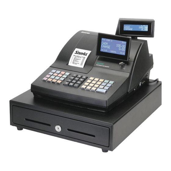
: 192 x 64 dot, Graphic LCD, Blue backlight(White LED) Display Customer : 16set x 2 line + Icon , Negative , Blue backlight(White LED) Raised Key : 48 key (with CAP), NR-500R Key Board Flat Key : 90 key (with water proof), NR-500 Drawer... - Page 8 2 Product Specifications 2-2 Appearance 2-2 A. Appearance Dimensions (mm) NR-500 (Flat Keyboard) NR-500R (Raised Keyboard) Figure2-1 Dimensions 2-2 B. Location Feature Printer Cover Key Board Drawer Customer Display Operator Display Mode Key RS-232 Serial I/F Connector Figure2-2 Location Feature...
-
Page 9: Thermal Printer Specification
Head Temperature Thermistor Sensor Out-of-paper Detection Reflection type photo interrupter Platen Position Detection Mechanical Switch (Option) Reliability Life 50km or more Dimension (mm) 70.3 (W) ×32.7 (D) ×15.3 (H) Weight Approx. 44 g Table2-2 Thermal Printer Specification SAM4S NR-500 SERIES... -
Page 10: Paper Specification
Table2-4 Character Specification 2-4 Power Specification Item Description Remark Input Voltage AC 100-240V, 50-60Hz (Min : 90V, Max : 265V) Power Consumption Regularity : Approx. 10W Output Voltage Power Adapter Output DC 9V / 2.5A Table2-5 Power Specification SAM4S NR-500 SERIES... -
Page 11: Interface Specification
For Bar Code Reader Voltage Supply or other devices #1-Pin of RJ45 Connector. Table2-11 RS-232C Specification 2-5 A-(b) Cable Connection & ) Figure2-4 RS232C Cable Connection (9Pin to 9Pin) & ) Figure2-5 RS232C Cable Connection (9Pin to 25Pin) SAM4S NR-500 SERIES... - Page 12 This Signal indicates whether the ECR(NR-500) is busy. (H/W flow control) MARK(Logic1) : The ECR is busy Output SPACE(Logic0) : The ECR is not busy The host transmits a data to the ECR, after confirming this signal. Table2-13 RS-232C Signal Description SAM4S NR-500 SERIES...
- Page 13 Caution: If the device with 5V/150mA is connected to Serial #1, the VCC of Serial #2 can not use. If the device with 100mA is connected to Serial #1, Other device with 50mA can be connected to Serial #2 Port. SAM4S NR-500 SERIES...
- Page 14 ECR. If the ECR is released from busy, the ECR transmits XON(ASCII 11h) to host through the Serial Data Line. Then the host recognizes that the ECR is not busy. And the host transmits a data to the ECR. SAM4S NR-500 SERIES...
- Page 15 Differential Data Line Green Differential Data Line Black Signal GND 2-5 B-(c) USB Interface Cable USB A TYPE USB A TYPE ( USB I/F CABLE ) OTHER NR-500 SIDE DEVICE SIDE USB B TYPE USB A TYPE SAM4S NR-500 SERIES...
- Page 16 ( NR-500 to HOST IRC I/F CABLE ) 1(ENET TX+) 1(ENET TX+) 2(ENET TX-) 2(ENET TX-) 3(ENET RX+) 3(ENET RX+) 4(N.C) 4(N.C) 5(N.C) 5(N.C) 6(ENET RX-) 6(ENET RX-) 7(N.C) 7(N.C) 8(N.C) 8(N.C) ( NR-500 to HUB IRC I/F CABLE ) 2-10 SAM4S NR-500 SERIES...
- Page 17 2-6 Drawer Kick-Out Specification 2-6 A. Drawer Signal Description Pin No Signal Name Direction Function Signal GND DRAWER Drawer Kick-Out Driver Signal DRA_COMP Drawer Open / Close Signal +24V Supply DC +24V Frame GND ( DRAWER CONNECTOR ) SAM4S NR-500 SERIES 2-11...
- Page 18 2 Product Specifications MEMO 2-12 SAM4S NR-500 SERIES...
-
Page 19: System Configuration
3 Installation and Operation 3-1 System Configuration Figure 3-1 System Configuration SAM4S NR-500 SERIES... -
Page 20: Paper Roll Installation
Spool Winding. (Fig 3-2(G)) 8. Insert the Spool Winding in 2~3 turns and place it on the Paper Supply. If it loosen, turn to tighten it. (Fig 3-2(H)) 9. Replace the printer cover. (Fig 3-2 (I)) Figure 3-2 Paper Installation SAM4S NR-500 SERIES... - Page 21 Factory option Table 3-1 Option 3-2 D. Supplies Item Description Remark 1 EA (1-station) Paper Roll 2 EA (2-station) Mode Key VD, REG, Z, P, C User Manual 1 EA Spool 1 EA (2-station only) Table 3-2 Supplies SAM4S NR-500 SERIES...
-
Page 22: Operation
VOID, OFF, Register(REG), Manager(X), Clear Totals(Z), Program(PGM) VOID, OFF, Register(REG), Manager(X), Clear Totals(Z), Program(PGM), Service ALL POSITIONS Mode(S) Table3-4 Key Function Note : The Key can be removed from the key lock in the OFF or REG position. SAM4S NR-500 SERIES... - Page 23 3 Installation and Operation SAM4S NR-500 SERIES...
-
Page 24: Key Board Matrix
LEVEL2 CASH Figure3-5 Raised Keyboard (NR-510R / NR-520R) DETL FEED RCPT CLERK (PAGE ) (PAGE ) FEED ERROR CORR RCPT CLEAR X/TIME ON/OFF CHARGE1 #NOSALE CHECK VOID SBTL RETURN CASH CANCEL Figure3-6 Flat Keyboard (NR-510 / NR-520) SAM4S NR-500 SERIES... -
Page 25: Initial Clear
5. Press the CASH key. ARE YOU SURE? Y=CASH N=CLEAR 6. Press the CASH key. The message "INITIAL CLEAR OK” prints when the initial clear is complete. To resume operations, you will need to sign on a clerk. SAM4S NR-500 SERIES... -
Page 26: All Clear
5. Press the upper left key of the keyboard, then the lower left key, then the upper right key, and finally press the lower right key. PRICE PRICE Figure3-9 <Raised Keyboard – NR-510R / NR-520R> Figure3-10 <Flat Keyboard – NR-510 / NR-520> SAM4S NR-500 SERIES... - Page 27 = = = = = = = = = = = = = = = = VERSION : NR-500 : STD 00.001 CHECKSUM : 084F BOOT/APP : BFBC/4893 PLUs USED : 60/2000 KEYBOARD : 90 KEYs 03.27 2014 CLERK 00 No.000001 00000 Figure3-11 All Clear Key Sequence & Print Sheet SAM4S NR-500 SERIES...
- Page 28 3. From the INTERFACE menu, Press ‘2’ to select SERIAL 2. 4. If error occurs, the message “ ** NG ** ” is displayed on LCD and the Buzzer beep. 5. Press the ‘CLEAR’ key to return to SELF TEST menu. 3-10 SAM4S NR-500 SERIES...
- Page 29 3. From the INTERFACE menu, Press ‘5’ to select MICRO SD. 4. If MICRO SD card is OK, “ ** OK ** “ message will be displayed. 5. Press the ‘CLEAR’ key to return to SELF TEST menu. SAM4S NR-500 SERIES 3-11...
- Page 30 YOU MUST USE Port #1. Use the following cable: Part # 522120 (Register DB-9MF COM 1 to PC DB-9F) Boot Area Update 1. Connect the Serial Cable From ECR to PC. 2. At the register, move to the SERVICE MODE. 3-12 SAM4S NR-500 SERIES...
- Page 31 At the ECR, when the load is complete, a rapid beep-beep-beep will be heard, and the display will flash rapidly. Turn the power switch to OFF, the program update is complete. 12. Disconnect the PC cable. SAM4S NR-500 SERIES 3-13...
- Page 32 3 Installation and Operation Perform a memory all clear on the ECR. The ECR is now ready to program or to load a previously saved end-user program. 3-14 SAM4S NR-500 SERIES...
-
Page 33: Disassembly And Assembly
2. Remove the two screws(B5) on the ASS'Y COVER MODE S/W(B1) and separate the MODE KEY ASS’Y(B4) from the PMO-COVER MODE S/W(B1). (Page6-3) 3. Remove the two screws(B2) on the MODE KEY ASS’Y(B4) and separate the IPR-BRKT MODE S/W(B3) and the MODE KEY ASS’Y(B4). (Page6-3) SAM4S NR-500 SERIES... - Page 34 1. Separate the harness( ) from the PBA-MAIN BOARD(E4). (Page6-13) 2. Remove the two screws(E15) from the IPR-BRKT TRANS(E25). (Page6-13) 3. Separate the PMO-HOLDER ADAPTER(E16) from the PMO-CASE LOWER(E30).(Page6-13) 4. Separate the harness( ) and Remove the ADAPTER(E16). (Page6-13) SAM4S NR-500 SERIES...
-
Page 35: Maintenance And Adjustment
Use in places where the products are exposed to sea winds or corrosive gases, including CL S, SO and NO d. Use in places where the products are exposed to static electricity or electromagnetic waves e. Use of the products in places subject to dew condensation. SAM4S NR-500 SERIES... - Page 36 5 Maintenance and Adjustment MEMO SAM4S NR-500 SERIES...
-
Page 37: Exploded Views And Parts List
6. Exploded Views and Parts List 6-1. Exploded View (NR-520R) Figure 6-1 Total Disassembly (NR-520R) SAM4S NR-500 SERIES... - Page 38 6 Exploded Views and Parts List 6-1. Exploded View (NR-520) Figure 6-2 Total Disassembly (NR-520) SAM4S NR-500 SERIES...
- Page 39 MEA-COVER PRINTER:NR-520 IVORY JK95-70675C MEA-COVER PRINTER:NR-510B BLACK JK95-70675D MEA-COVER PRINTER:NR-520B BLACK JK72-20980A PMO-COVER DUMMY NR-510 IVORY JK72-20980B PMO-COVER DUMMY NR-510 BLACK JK72-20026A PMO WINDOW JOURNAL NR-520 JK72-20977A PMO-COVER PRINTER IVORY JK72-20977B PMO-COVER PRINTER BLACK JK70-20304A IPR-CUTTER PAPER SAM4S NR-500 SERIES...
- Page 40 6 Exploded Views and Parts List B. ASS’Y CASE-UPPER(NR-500R) Figure 6-3 ASS’Y CASE-UPPER(NR-500R) SAM4S NR-500 SERIES...
- Page 41 6 Exploded Views and Parts List 6-2. B. ASS’Y UPPER(NR-500R) Parts No. Description / Specification Q`ty Design-Location Serviceable Remark PMO-COVER MODE S/W: JK72-21005G BLACK NR-500RB,STD,HIPS(V0),BLK,SPRAY S600200011A SCREW-TAPPING:PH,M3,L8 JK70-20309A IPR-BRKT MODE_S/W JK95-70098A MODE KEY ASSY S600200011A SCREW-TAPPING:PH,M3,L8 JK95-70596C ELA-LCD FRONT IVORY...
- Page 42 6 Exploded Views and Parts List 6-2 B. ASS’Y CASE-UPPER(NR-500) Figure 6-4 ASS’Y CASE-UPPER(NR-500) SAM4S NR-500 SERIES...
- Page 43 PMO-CASE UPPER:NR-500 IVORY JK72-20213B PMO-CASE UPPER:NR-500F IVORY JK72-20213F PMO-CASE UPPER:ER-390B,BLK,SPRAY BLACK JK72-20213G PMO-CASE UPPER:ER-390BF,BLK,SPRAY BLACK S600200006A SCREW-TAPPING:PWH,M3,L8 JK75-20033A ASSY-KBD HOUSING IVORY ASSY-KBD HOUSING:90FLAT(WITH W/PO), JK75-20033C BLACK BLK,SPRAY JK59-30027A UNIT-KEYBOARD:ER-390,90 KEY,FLAT,IVORY IVORY UNIT-KEYBOARD:NR-510B/520B, JK59-30027B BLACK 90 KEY,FLAT,BLACK S600200006A SCREW-TAPPING:PWH,M3,L8 SAM4S NR-500 SERIES...
- Page 44 6 Exploded Views and Parts List C. ASS’Y PRINTER Figure 6-5 ASS’Y PRINTER SAM4S NR-500 SERIES...
- Page 45 IPR-BRKT SPOOL MOTOR NR-520 S600100023A SCREW-MACHINE:BH,,M2.6,L3 S600100034A SCREW-MACHINE:PWH,M3,L14 JK72-20316A PMO-COVER_SD JK72-20978A PMO-HOLDER PRINTER JK92-10059J PBA PRT JOINT:NR-500,SVC JK39-40565A CABLE-FFC:ER-260,30P,1.0mm,300mm JOURNAL S600200006A SCREW-TAPPING:PWH,M3,L8 JK39-50005A CABLE-FFC:ER-230,30P,1.0mm,160mm RECEIPT JK92-10039A PBA SUB:SD CARD JK70-20122A IPR-BRKT SD JK39-40756B HARNESS-SD:ER-230,10P,220mm,AT TAPE S600200006A SCREW-TAPPING:PWH,M3,L8 S600100016A SCREW-MACHINE:PWH,M3,L4 SAM4S NR-500 SERIES...
- Page 46 6 Exploded Views and Parts List D. ASS’Y KBD(48KEY RAISED) Figure 6-6 ASS’Y-KEYBOARD (48 Key) SAM4S NR-500 SERIES 6-10...
- Page 47 JK59-30077C UNIT-KEYBOARD:NR-520R,RAISED,48KEY IVORY JK59-30077D UNIT-KEYBOARD:NR-520RB,RAISED,48KEY BLACK JK72-20483A KEY NUMBER SET JK72-20476A PMO-KEY CAP_1X1 JK72-20479A PMO-KEY TOP_1X1 JK81-20061A RETURN-SPRING JK72-20477A PMO-KEY CAP_1X2 JK72-20480A PMO-KEY TOP_1X2 JK81-20052A PMO-KBD FRAME_48,RAISED JK81-20052D CONTACT-RUBBER_48 JK81-20052C ASSY-FPC,48KEY,RAISED JK81-20052B IPR-BOTTOM PLATE_48 S600200006A SCREW-TAPPING:PWH,M3,L8 6-11 SAM4S NR-500 SERIES...
- Page 48 6 Exploded Views and Parts List 6-2 D. ASS’Y KBD(90KEY FLAT) Figure 6-7 ASS’Y-KEYBOARD (90 Key) SAM4S NR-500 SERIES 6-12...
- Page 49 6-2. D. ASS’Y KBD(90KEY FLAT) Parts No. Description / Specification Q`ty Design-Location Serviceable Remark JK59-30027A UNIT-KEYBOARD:ER-390,90 KEY,FLAT IVORY JK59-30027B UNIT-KEYBOARD:ER-390B,90 KEY,FLAT BLACK JK81-20049A FRAME:90 KEY JK81-20049B KEY-RUBBER:90 KEY JK81-20049C FPC-ASSY:90 KEY JK81-20049D BASE-PLATE:90 KEY JK81-20049E SCREW-TAPPING:M2.6X8 SAM4S NR-500 SERIES 6-13...
- Page 50 6 Exploded Views and Parts List 6-2 E. ASS’Y CASE-LOWER Figure 6-8 ASS’Y CASE-LOWER 6-14 SAM4S NR-500 SERIES...
- Page 51 SCREW-ASSY TAPT: BH,M4,L8 S600200003A SCREW-TAPPING:PH,M4,L10 JK70-20307A IPR-BRKT CASING JK72-20964P PMO-CASE LOWER IVORY PMO-CASE LOWER:NR-500,2SERIAL, JK72-20964W BLACK NO HOLE,BLK,SPRAY HARNESS-POWER S/W:NR-500, JK39-40688D 2P,270mm,SOLTEAM,OR-L-11D,DOT MARK,DC JK39-30002A POWER-CORD:NR-500,EUROPE,220V,IVORY EUROPE JK39-30002B POWER-CORD:NR-500,USA,110V,IVORY IVORY JK39-30002C POWER-CORD:NR-500,AUSTRALIA,240V,IVORY AUSTRALIA JK39-30002D POWER-CORD:NR-500,UK,240V,IVORY JK39-30001A POWER-CORD:NR-500,EUROPE,220V,BLACK EUROPE BLACK 6-15 SAM4S NR-500 SERIES...
- Page 52 6 Exploded Views and Parts List JK39-30001B POWER-CORD:NR-500,USA,110V,BLACK JK39-30001C POWER-CORD:NR-500,AUSTRALIA,240V,BLACK AUSTRALIA JK39-30001D POWER-CORD:NR-500,UK,240V,BLACK JK39-40603A HARNESS DRA/COM;4PIN,180mm JK92-10139A PBA MICRO-SD:NR-300F,W/O STARCAP JK39-40756B HARNESS-SD:ER-230,10P,220mm,AT TAPE 6-16 SAM4S NR-500 SERIES...
- Page 53 6 Exploded Views and Parts List F. ASS’Y-DRAWER(G-DRAWER:4B8C,5B6C) A.ASS’Y BILL- COIN (4B8C) B.ASS’Y HOU- SING A.ASS’Y BILL- COIN (5B6C) C.ASS’Y LOCK E.ASS’Y TRAY D.ASS’Y BOT- Figure 6-9 ASS’Y-DRAWER (G-DRAWER:4B8C,5B6C) SAM4S NR-500 SERIES 6-17...
- Page 54 6 Exploded Views and Parts List F. ASS’Y-DRAWER(G-DRAWER:4B8C,5B6C) Figure 6-10 Lubrication Points of the G-Drawer(4B8C,5B6C) Code No. Description / Specification Q`ty Serviceable Remark 0201-002010 GREASE-N2 Minimum Serviceable Packing Weight : 40g 0201-002009 GREASE-N1 Minimum Serviceable Packing Weight : 40g 6-18 SAM4S NR-500 SERIES...
- Page 55 MEA-UNIT LOCK(12V,COM) JK97-20093D MEA-UNIT LOCK(24V,COM) JK33-10500A SOLENOID-DC: 24V JK33-10500D SOLENOID-DC: 12V 6001-000525 SCREW-TAPTITE: M3,L14 JK70-50079A SCREW-TAPTITE: M3,L5 JK39-40301R CBF HARNESS : MICRO S/W 6107-001041 SPRING-LOCK LEVER JK97-01080B MEC-SUB LOCK JK70-30019A SPRING-PUSH JK70-50090A PLAIN-WASHER JK70-50092A SCREW-TAPTITE: M5,L10 SAM4S NR-500 SERIES 6-19...
- Page 56 JK70-20108C IPR-FRONT PANEL(4B8C,WHT) JK70-20108D IPR-FRONT PANEL(4B8C,BLK) Jk75-20067A MEC-KEY LOCK JK75-20041A MEC-KEY LOCK: #2424 OPTION JK70-20025B IPR-KEY DRAWER 1SET JK70-20075A IPR-KEY DRAWER: #2424 1SET OPTION 6044-000231 RING-E: ID5 JK70-20074A IPR-LEVER LOCK JK70-20120A IPR-DUMMY KEY JK70-50094A SCREW-TAPTITE: M3,L8 6-20 SAM4S NR-500 SERIES...
- Page 57 6 Exploded Views and Parts List MEMO SAM4S NR-500 SERIES 6-21...
- Page 58 7 PCB Layout and Parts List 7-1 Main PCB Layout SAM4S NR-500 SERIES...
- Page 59 R-CHIP:100 OHM,5%,1/10W,1608 S2008000012 R-CHIP:200 OHM,5%,1/10W,1608 R4,R5,R23,R24 S2008000013 R-CHIP:220 OHM,5%,1/10W,1608 R127,R130 R15,R28,R32,R54,R57,R60,R S2008000016 R-CHIP:300 OHM,5%,1/10W,1608 85,R86,R101,R134 S2008000020 R-CHIP:470 OHM,5%,1/10W,1608 R146,R150 R2,R10,R13,R25,R31,R44,R5 S2008000026 R-CHIP:1KOHM,1%,1/10W,1608,1% 6,R58,R61,R77,R115,R116,R 141,R145,R149,R152 S2008000028 R-CHIP:1.5KOHM,1%,1/10W,1608,1% R111 S2008000030 R-CHIP:2KOHM,5%,1/10W,1608 R52,R53 S2008000031 R-CHIP:2.2KOHM,5%,1/10W,1608 R83,R107 R73,R78,R87,R100,R118,R1 S2008000037 R-CHIP:4.7KOHM,1%,1/10W,1608,1% 65,R166,R167,R168,R169,R1 70,R171,R172 SAM4S NR-500 SERIES...
- Page 60 C2,C3,C4,C5,C6,C7,C8,C9,C 10,C11,C20,C21,C23,C24,C2 7,C30,C31,C36,C43,C44,C45 S2204000028 C-CERAMIC,CHIP:100nF,+80-20%,25V,Y5V,1608 ,C46,C48,C50,C51,C57,C58, C63,C64,C66,C67,C70,C72,C 74,C75,C76,C77,C78,C79,C8 6,C89,C90,C91,C103,C105 S2205000002 C-TANTAL:10uF,16V,3528 CE5,CE7,CE10 S280100018A CRYSTAL-SMD:32.768KHz,20PPM,MC-146 S2801003388 CRYSTAL-SMD:12MHz,SX-1,16pF S3711004118 WAFER;BOX-HEADER,1R, 3P,1.25mm,SMD S3711004123 WAFER;BOX-HEADER,1R, 8P,1.25mm,SMD S3711004125 WAFER;BOX-HEADER,1R,10P,1.25mm,SMD CN7,CN8,CN9,CN10 CONNECTOR-MICRO SD:9P,PUSH PUSH,DM3AT-SF- S371200009A SCN1 PEJM5,HIROSE JK41-10928B PCB-MAIN:NR-500,3SERIAL,FR-4,2L,T1.6mm JK39-40541C CBF HARNESS-GND:ER-850,UL1015#18,60mm GND-WIRE SAM4S NR-500 SERIES...
- Page 61 7 PCB Layout and Parts List 7-2 Printer Joint PCB Layout Part-No Description / Specification Q’TY Design Location Serviceable Remarks JK92-10059J PBA PRT JOINT:NR-500,SVC ASSY S3708001395 CONNECTOR-FPC/FFC/PIC:30P,1mm,ST,DIP,TOP JCN2 S3708001397 CONNECTOR-FPC/FFC/PIC:30P,1mmAN,DIP,SIDE JCN1 JK41-10034B PCB-I/F & PRT JOINT:NR-500,FR-4,2L,T1.6 SAM4S NR-500 SERIES...
- Page 62 R-CHIP:1KOHM,1%,1/10W,1608,1% R1,R10,R11,R14,R15 S2008000030 R-CHIP:2KOHM,5%,1/10W,1608 S2008000037 R-CHIP:4.7KOHM,1%,1/10W,1608,1% R8,R9,R12,R13 S2008000044 R-CHIP:10KOHM,1%,1/10W,1608,1% R3,R6,R16 S2008000063 R-CHIP:100KOHM,5%,1/10W,1608 S2204000004 C-CERAMIC,CHIP:22pF,5%,50V,1608 C4,C5 S2204000018 C-CERAMIC,CHIP:1nF,10%,50V,X7R,1608 S2204000028 C-CERAMIC,CHIP:100nF,+80-20%,25V,Y5V,1608 C1,C2,C6,C7,C8,C9,C10 S2205000002 C-TANTAL:10uF,16V,3528 CE3,CE4 S2402000168 C-AL,SMD:100uF,20%,16V,F60,Ø6.3×5.7L S2402000180 C-AL;SMD,470uF,16V,MVG S370400001A SOCKET-SIM CARD:SMD,8P S371200035A SMD_CONNECTOR_AXK500147YG_100PIN S3711004123 WAFER;BOX-HEADER,1R, 8P,1.25mm,SMD JK41-10035A PCB-GPRS:ER-420EJ,FR-4,2L,T1.6 SAM4S NR-500 SERIES...
- Page 63 Design Location Serviceable Remarks JK92-10039A PBA SUB:NR-300,SD CARD ASSY UNIT-SDHC CARD: JK46-00016C SD CARD SD CARD ER-230EJ,4GB,SANDISK,MLC,CLASS4 JK39-40756D HARNESS-SD:NR-300/ER-230EJ,10P,220mm HARNESS JK70-20122A IPR-BRKT SD;NEX1,SECC T1.0 BRACKET S2204000004 C-CERAMIC,CHIP:22pF,5%,50V,1608 S3711004125 WAFER;BOX-HEADER,1R,10P,1.25mm,SMD SCN1 S3712000060 CONNECTOR-SD CARD:SMD,12P,RoHS SCN2 JK41-10019A PCB-SD CARD:NR-300,FR-4,2L,T1.6 SAM4S NR-500 SERIES...
- Page 64 Description / Specification Q'TY Design-location Serviceable Remark JK92-10139A PBA MICRO-SD:NR-300F,W/O STARCAP MICRO SD B'D JK39-40756B HARNESS-SD:ER-230,10P,150mm,AT TAPE SCN1 (SD HARNESS) S110900004A UNIT-MICRO SD CARD:SDHC,4GB,SANDISK,CLASS4,MLC MICRO SD 4GB S3711004125 WAFER;BOX-HEADER,1R,10P,1.25mm,SMD SCN1 S371200009A CONNECTOR-MICRO SD:9P,PUSH PUSH SCN2 JK41-10935A PCB-MICRO SD:NR-300(SER),FR-4,2L,T1.6mm SAM4S NR-500 SERIES...
- Page 65 HARNESS-FISCAL:34P,130mm,2mm,AT TAPE HARNESS S2204000028 C-CERAMIC,CHIP:100nF,+80-20%,25V,Y5V,1608 JK41-10574A PCB-FISCAL:PLCC32,34P,FR-4,2L,BOARD-IN 7-6-2 Memory Size = 4MBITs Part-No Description / Specification Q’TY Design Location Serviceable Remarks JK92-10037A PBA SUB-FISCAL:ER-230,34P,4MBIT,3.3V ASS'Y S110200002A IC-OTP ROM:AT27LV040A-90JU,512Kx8BIT U1 (4MBITs) JK39-40771A HARNESS-FISCAL:34P,130mm,2mm,AT TAPE HARNESS S2204000028 C-CERAMIC,CHIP:100nF,+80-20%,25V,Y5V,1608 JK41-10574A PCB-FISCAL:PLCC32,34P,FR-4,2L,BOARD-IN SAM4S NR-500 SERIES...
- Page 66 7-7-2 OLD SERIAL 2-PORT (~Dec. 2015) Max. 2-PORT (SVC only) Part-No Description / Specification Q’TY Design Location Serviceable Remarks JK92-10059K PBA INTERFACE:NR-500(2),232*2,W/O ETHERNET,SVC ASSY S3701000232 CONNECTOR-DSUB:9P,2R,FEMALE,ANGLE,AUF S3708001395 CONNECTOR-FPC/FFC/PIC:30P,1mm,ST,DIP,TOP S3712000048 CONNECTOR-USB HOST:USB A TYPE,DIP,AN S3712000051 CONNECTOR-USB;B-TYPE,4P,2R,AN,DIP S3722000212 JACK-MODULAR:8P/8C,-,N,ANGLE,-,N,GRY,AU5 JK41-10033B PCB-INTERFACE:NR-500,FR-4,2L,T1.6 SAM4S NR-500 SERIES...
-
Page 67: Troubleshooting
2. Check the VBT(Battery Voltage). 3. Check the TR(Q27,Q28;2222) on Main PBA 4. Replace the SRAM. 1. Check the VBT(Battery Voltage). RTC Ok? 2. Check the RTC Clock 32.768KHz (X3) 3. Replace the X-TAL 4. Replace the RTC Chip (U31) SAM4S NR-500 SERIES... -
Page 68: System Problem
2. Check the VBT(Battery Voltage). 3. Check the TR(Q27,Q28;2222) on Main PBA 4. Replace the SRAM. 1. Check the VBT(Battery Voltage). RTC Ok? 2. Check the RTC Clock 32.768KHz (X3) 3. Replace the X-TAL 4. Replace the RTC Chip (U31) SAM4S NR-500 SERIES... - Page 69 2. Check the SCLK Signal (CPU P9.1) LCD Display 3. Check the SDAT Signal (CPU P4.7) 4. Check the Harness. 1. Check the LCD. LCD PBA 2. Check and Replace the LCD MODULE PBA. Assy Ok? 3. Check the LCD Harness. SAM4S NR-500 SERIES...
- Page 70 2. Check the VPH voltage. Source voltage is VPRT 3. Check the VPH ON/OFF circuit and pattern. 4. Check the FDS4141(U8), MMBT2222(Q24) on Main PBA 5. Check the JOINT B’D and FFC harness. 6. Check and Replace the printer. SAM4S NR-500 SERIES...
-
Page 71: Key Board Problem
4. Check the Key Return part 74LVC541(U28) Failure ? 5. Check the related Circuit and Pattern 1. Check the affected Key Specific Key 2. Check the Matrix Bus & Data Bus Failure? 3. Check the Diodes(BAT43WS) 4. Check the Key Board Assy SAM4S NR-500 SERIES... - Page 72 3. Check the related circuit & Component TR TIP102(Q3) Failure ? 4. Check the Harness and Solenoid in the Drawer. 5. Check the Drawer Signal (CPU P8.7) 1. Check the Compulsory Harness & Connector. Compulsory 2. Check the Micro switch in the Drawer. Failure? SAM4S NR-500 SERIES...
-
Page 73: Rs-232C Serial Communication Problem
3. Check whether Signal is affected by the Cable Noise. 1. Check the connection of the H/W handshaking Line and Other side H/W Handshake 2. Check the I/F Cable whether it is open or short. 3. Confirm the H/W handshaking Protocol. SAM4S NR-500 SERIES... - Page 74 8 Troubleshooting MEMO SAM4S NR-500 SERIES...
-
Page 75: Block Diagram
KEY B`D INTERFACE SCAN RETURN 30 PIN 30 PIN FFC CABLE FFC CABLE 34 PIN HARNESS 30 PIN 30 PIN PRINTER PRINTER FPC CABLE FPC CABLE JOINT BOARD JOINT BOARD OTP-ROM Journal PRINTER Receipt PRINTER FISCAL B'D SAM4S NR-500 SERIES... - Page 76 9 Block Diagram MEMO SAM4S NR-500 SERIES...
-
Page 77: Wiring Diagram
10 Wiring Diagram 10-1 Wiring Pin Connection SAM4S NR-500 SERIES 10-1... - Page 78 FA(14) DTR0_OUT TPH_STB(J)# FISEPROM_CE DSR1_IN TPH_STB(J)#1 FA(15) TXD1_OUT SEN_THERMIST_IN FA(4) RXD1_IN TPH_STB(R)#2 FA(0) DTR1_OUT TPH_STB(R)#1 FA(5) VUSB TPH_LAT FA(1) SEN_PEND_2INCH FA(6) USB_DM / USB_DRPD SEN_PRTDISCON FA(2) USB_DP / USB_DPRPD / USB_DPUPE SEN_PEND_PS FA(7) FA(3) FA(17) FA(16) 10-2 SAM4S NR-500 SERIES...
- Page 79 VDD33V RETURN-2 CN19 = Flash memory Connector RETURN-3 VDD33V RETURN-4 SPI0_SF_CS1 RETURN-5 SPI1_DO RETURN-6 SPI1_CLK RETURN-7 SPI1_DI RETURN-8 SERIAL FLASH WP (Pull up) SERIAL FLASH HOLD (Pull up) CN20 = Power fail Connector VDD33V Not connection SAM4S NR-500 SERIES 10-3...
- Page 80 10 Wiring Diagram MEMO 10-4 SAM4S NR-500 SERIES...
- Page 81 3. Printer Joint PCB Schematics. ---------------------------------- 11-15 4. Serial Interface PCB Schematics. ------------------------------ 11-16 5. GPRS PCB Schematics. -------------------------------------------- 11-17 6. External SD Card PCB Schematics. ---------------------------- 11-18 7. Micro SD Card PCB Schematics. -------------------------------- 11-19 11-1 SAM4S NR-500 SERIES...
- Page 82 11-2 CPU PART VREFL0 VREFL VREFH VREFH0 VSS_USB AVCC0 AVSS0 VBATT VCC_USB PC7/ET_COL GPRS_DTR EMLE EMLE P34/TRST# TRSTN P31/TMS TDI/RXD1 P27/TCK/SCK1 P26/TDO/TXD1 11-2 SAM4S NR-500 SERIES...
- Page 83 11-3 MEMORY, SD, MICRO SD PART CON-BOX;10P,1.25MM,ST,12505WS BS62LV4006SC70 SDCARD MICRO BS62LV4006SC70 SAM4S NR-500 SERIES 11-3...
- Page 84 11-4 KEY SCAN, BUZZER, BATTERY PART R172 4.7K R171 4.7K R170 4.7K R169 4.7K R168 4.7K R167 4.7K R166 4.7K R165 4.7K 74LVC541 74LVC138 74LVC138 11-4 SAM4S NR-500 SERIES...
- Page 85 11-5 DRAWER, USB PART SAM4S NR-500 SERIES 11-5...
-
Page 86: Lcd Display Part
11-6 LCD DISPLAY PART CON-BOX;10P,1.25MM,ST,12505WS CON-BOX;8P,1.25MM,ST,12505WS 11-6 SAM4S NR-500 SERIES... -
Page 87: Printer Part
11-7 PRINTER PART 74LVC541 SAM4S NR-500 SERIES 11-7... - Page 88 11-8 ETHERNET CONTROLLER PART 1V8_OUT VCC1V8D GNDD VCC1V8D GNDD VCC1V8D GNDD VCC1V8D GNDD GNDD IC-CONTROLLER;W5100,ETHERNET VCC1V8A GNDD VCC1V8A GNDA GNDA VCC3V3A GNDA VCC3V3D VCC3V3D VCC3V3D 11-8 SAM4S NR-500 SERIES...
- Page 89 11-9 FISCAL LOGIC PART 100pF 100pF 100pF 100pF 100pF 100pF C100 100pF C101 100pF C102 74LVC574 74LVC574 74LVC574 74LVC541 74LVC574 74LVC138 SAM4S NR-500 SERIES 11-9...
- Page 90 11-10 FISCAL INTERFACE PART 100nF 100nF 11-10 SAM4S NR-500 SERIES...
- Page 91 11-11 POWER, POWER FAIL PART SAM4S NR-500 SERIES 11-11...
- Page 92 11-12 ADAPTOR INPUT, VPH PART CN3:2 CN3:1 11-12 SAM4S NR-500 SERIES...
- Page 93 11-13 SERIAL INTERFACE PART R174 R173 SAM4S NR-500 SERIES 11-13...
- Page 94 11-14 FISCAL PCB M27W201 SAM4S ER-420EJ SERIES 11-14...
- Page 95 11-14 PRINTER JOINT PCB SAM4S NR-500 SERIES 11-15...
- Page 96 11-16 SERIAL INTERFACE PCB USB A Type 49.9 49.9 49.9 49.9 11-16 SAM4S NR-500 SERIES...
- Page 97 11-17 GPRS PCB Q2686RD CON-BOX;10P,1.25MM,ST,12505WS SAM4S NR-500 SERIES 11-17...
- Page 98 11-18 EXTERNAL SD PCB SDCARD 11-18 SAM4S NR-500 SERIES...
- Page 99 11-19 Micro SD PCB SDCARD MICRO CON-BOX;3P,1.25MM,ST,12505WS SAM4S NR-500 SERIES 11-19...
-
Page 100: Update Log
Use this page to record any special servicing information such as Service Bulletins or Supplements. When possible, record changes to Code numbers directly on the actual Parts List. Always records Service Bulletin numbers and Application Dates on this log to ensure that your data is as current as possible. SAM4S NR-500 SERIES... - Page 102 Shin Heung Precision. Oct. 2017 Printed in KOREA V1.6...
Need help?
Do you have a question about the NR-500R and is the answer not in the manual?
Questions and answers