Table of Contents
Advertisement
Quick Links
Advertisement
Table of Contents

Related Manuals for Craftex CX102


Summary of Contents for Craftex CX102
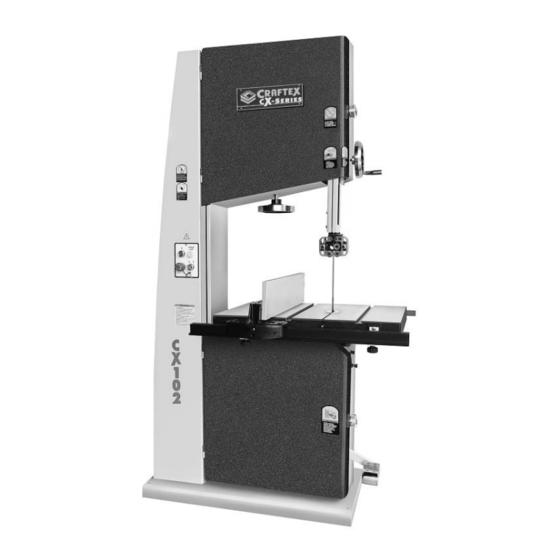
- Page 1 CX102 22” 5-HP BAND SAW User Manual...
-
Page 2: Table Of Contents
TABLE OF CONTENTS General Safety Instructions ............... 3 CX102 Specific Safety Instructions ........... 4 Features .................... 5 Physical Features................6 Set Up ....................7 Unpacking & Inventory ..............7 Moving CX102................... 8 Proper Grounding................8 Assembly................... 9 Blade Tracking Adjustment ............... 11 Test Run.................... -
Page 3: General Safety Instructions
GENERAL SAFETY INSTRUCTIONS Extreme caution should be used when operating all power tools. Know your power tool, be familiar with its operation, read through the owner’s manual and practice safe usage procedures at all times. ALWAYS read and understand the router bits, shaper heads, blades, user manual before operating the knives or making other adjustments or... -
Page 4: Cx102 Specific Safety Instructions
ALWAYS ensure that the band saw your band saw, before operating the blade guard is no more than 1/2” above CX102. If you fail to do so, serious injury the stock. could occur. WARNING The safety instructions given above can not be complete because the environment in every shop is different. -
Page 5: Features
CX102 a 22” Band Saw. The Craftex name guarantees Craft Excellence. By following the instructions and procedures laid out in this owner’s manual, you will receive years of excellent service and satisfaction. The CX102 is a professional tool and like all power tools, proper care and safety procedures should be adhered to. -
Page 6: Physical Features
CX102 – 22” BAND SAW PHYSICAL FEATURES Blade Tension One Piece Hand Wheel Construction Guide Post Hand Wheel Control Guide Panel Blocks Eye Bolts Cast Iron Blade Table Fence Tracking Adjustment Knob Front Fence Foot Rail Guide Brake Post Lock... -
Page 7: Setup
Use a solvent cleaner that will not damage the painted surfaces. WARNING CX102 is a very heavy machine, do not over-exert yourself. For safe moving method use fork truck or get the help of Figure-1 Inventory an assistant or friend. -
Page 8: Moving Cx102
MOVING CX102 PROPER GROUNDING Your CX102 is provided with two eye bolts Grounding provides path least which are installed on the top of the band resistance for electric current to reduce the saw. risk of electric shock. When moving the band saw, place the... -
Page 9: Assembly
(Figure-1 & Figure-2) Follow the steps below to assemble your CX102. The CX102 is equipped with two eye bolts, used to move the band saw. Install the bolts as shown in figure-4 and make sure they are threaded all the way in. - Page 10 Figure-7 Table insert and table pin Figure-9 Front fence rail attached Take the front fence rail brackets and Install the rear rail fence in the same attach them to the table using screws and manner. washers provided. See figure-8. Now take the fence and pull its handle up. Place the fence on the front fence rail and slide it against the blade.
-
Page 11: Blade Tracking Adjustment
Once you have attached the adhesive screws and washers provided as shown in backed scale to the rail, place the fence on figure-13. the rail and tighten it in place by pushing down the handle. See figure-11 Figure-13 Installing the foot pedal Figure-11 Fence installed on the rails BLADE TRACKING Take the hand wheel handle and slide it on... - Page 12 IMPORTANT In very rare cases if the blade tracking is not adjusted by tilting the upper wheel, then you will have to make minor adjustments to the angle of tilt of the lower wheel to get the blade centered on both wheels.
-
Page 13: Test Run
READ THE To make sure the control panel on your MANUAL CX102 is working properly, do the following: Turn the key to “0” and push the ON button. The key feature is not working properly, if Before starting the band saw, make sure the band saw turns on. -
Page 14: Foot Brake
Figure-18 OFF / RESET button Figure-19 Foot brake FOOT BRAKE WARNING The CX102 is equipped with a foot brake This machine can perform many types of used only for emergency to disconnect the operations which are beyond the scope power to the motor and to bring the wheels of this manual and are very dangerous if and the blade to a complete stop. -
Page 15: Blade Tension
The blade tension on CX102 can be any band saw. If the blade is too loose, adjusted by turning the hand wheel shown there is a possibility that the blade will slip in figure-13. -
Page 16: Guide Block Bearings Adjustment
GUIDE BLOCK BEARINGS ADJUSTMENT guide bearings (besides), thrust bearing (behind) the blade, support the blade to move in a straight line during cutting operation. Properly adjusted guide bearings play, an important role in getting accurate cuts. To adjust the guide block bearings, turn the Figure-23 Adjusting the thrust bearing machine off and disconnect the cord from the power source. -
Page 17: Table Stop Adjustment
Figure-27 Adjusting table to the blade ADJUSTMENT Once the table is at the 90° to the blade, CX102 features a table stop which allows tighten the table tilt bracket lock knob and the table to easily come to a 90° if the table table lock lever to hold the table in position. -
Page 18: Table Tilt Scale Calibration
TABLE TILT SCALE CALIBRATION To calibrate the table tilt scale: Make sure the table is at 90° to the blade and the blade tensioning and tracking is properly set. (See Page 11 & 15 for details) Disconnect the machine from the power source and loosen the pointer screw shown in figure-28. -
Page 19: Guide Post
GUIDE POST CAST IRON WHEELS The guide post assembly can be moved up The CX102 comes with heavy duty cast down above work-piece. iron wheels for added stability and overall movement of the guide post is controlled by performance. rotating the guide post hand wheel shown in figure-31. -
Page 20: Connecting To A Dust Collector
COLLECTOR Before cutting the work-piece, make sure to inspect it for nails, staples, small pieces of CX102 features two 4” diameter dust ports stone or metal and any other foreign to connect to a dust collector. objects which could come in contact with the blade. -
Page 21: Operations
Blade tension adjustment Blade tracking adjustment Guide bearings adjustment WARNING Figure-34 Ripping on CX102 CX102 produces fine dust particles during cutting operation which is very dangerous for health. Always connect CROSSCUTTING your band saw to a dust collector. Cutting solid wood across the grain and cutting plywood across the width of the work-piece is called crosscutting. -
Page 22: Resawing
RE-SAWING TABLE TILT Cutting a work-piece into two or more The CX102 is equipped with a 23” x 30” thinner pieces is called re-sawing. Wider table that can be tilted 10° right and 45° left blades give better result, when re-sawing. -
Page 23: Removing The Blade
REMOVING THE BLADE INSTALLING THE NEW BLADE To replace or change the blade, turn the switch OFF and disconnect the cord from Once the old blade is removed, carefully the power source. slide in the new blade through the slot on the table so that the teeth of the blade are Remove the fence and rails and release the pointing downwards. -
Page 24: Maintenance
MAINTENANCE 3. Remove blade (See page-23 During the life of your machine, you will Removing the Blade). need to practice some regular maintenance to keep your saw in peak performance 4. Loosen the nut securing the wheel to condition. the saw body and remove the wheel. The saw should be daily checked, for 5. -
Page 25: Unpainted Cast Iron
TENSIONING THE V-BELT BRUSHES Slide the motor down in the shaft and push The CX102 is equipped with a brush the V-belt with your finger. There should be located in the bottom cabinet, touching the 3/4” of deflection when pushing the V-belt. -
Page 26: Table Trunnions
Table Trunnions Make sure the switch is in the OFF position and the cord is disconnected from the power source. Open the table lock lever and tilt lock knob and move the table to its maximum 45° angle and lock the table lever. Clean the grease and saw dust buildup and apply a thin coat of all purpose grease to the trunnions. -
Page 27: Parts Breakdown & Parts List
CX102 PARTS BREAKDOWN... - Page 28 CX102 BODY PARTS BREAKDOWN REF# DESCRIPTION REF# DESCRIPTION BODY HEX BOLT 1/4"*3/4" HEX BOLT 5/16"*1 1/4" LOCK WASHER 1/4" LOCK WAWHER 5/16" FLAT WASHER 1/4" FLAT WASHER 5/16" BRAKE LEVER(S) SLIDEING HOUSING BRAKE LEVER(L) PHILLIPS HEAD SCREW 3/16"*1/2" BRUSH PLANE...
- Page 29 PIN 6*18MM SPRING ELECTRIC CONTACTOR ELECTRIC CONTACTOR PLANE PLANE STRAIN RELIEF HANDLE PHILLIPS HEAD SCREW 1/4"*3/4" STOP BUTTON ON BUTTON POWER LIGHT SWITCH TABLE BUTTON HEAD SCREW 5*10MM LIMIT SWITCH HEX BOLT 1/2"*4" HEX NUT 1/2" DEY SWITCH TERMINAL BOX CORD TUBE PLASTIC TUBE...
- Page 30 CX102 GUIDE POST ASSEMBLY PARTS BREAKDOWN...
- Page 31 CX102 GUIDE POST ASSEMBLY PARTS LIST REF# DESCRIPTION REF# DESCRIPTION 101 KNOB 5/16*2" 137 WORM 102 HEX BOLT 5/16"*3/4" 138 GEAR SHAFT 103 SLEEVE BEARING 139 GEAR 104 GUIDE BRACKET 140 GUIDE POST SCALE 105 SET SCREW 1/4"*1/4" 141 HAND WHEEL HANDLE...
- Page 32 CX102 TABLE PARTS BREAKDOWN...
- Page 33 CX102 TABLE PARTS LIST REF# DESCRIPTION SCREW LOCK KNOB ANGLE ADJUSTMENT PLANE ADJUSTMENT BAR BRACKET TABLE LOCK BLOCK SCALE TRUNNION HEX BOLT 3/8"*1 1/4" TRUNNION BASE 1/2" KNOB LOCK SHAFT ADJUSTING RING PRESS SHAFT HEX BOLT 1/4-20*3/8" LOWER BLADE COVER CAP SCREW 1/2"*1 1/2"...
- Page 34 CX102 FENCE ASSEMBLY PARTS BREAKDOWN...
-
Page 35: Parts List
CX102 FENCE ASSEMBLY PARTS LIST REF# DESCRIPTION FENCE BODY CAP SCREW 10*16 BUTTON HEAD SCREW 5*10MM FENCE BASE SET SCREW 1/4"*1/4" EXTERNAL RETAINING RING S10 BEARING ECCENTRIC SHAFT PRESSURE PLATE SCALE FRONT FENCE RAIL SQUARE NUT 5/16 CAP SCREW 1/4"*3/4"... -
Page 36: Warranty
This warranty shall not apply to consumable products such as blades, bits, belts, cutters, chisels, punches etceteras. Craftex shall in no event be liable for injuries, accidental or otherwise, death to persons or damage to property or for incidental contingent, special or consequential damages arising from the use of our products.
Need help?
Do you have a question about the CX102 and is the answer not in the manual?
Questions and answers