Sign In
Upload
Manuals
Brands
Hioki Manuals
Test Equipment
RM3543
Hioki RM3543 Manuals
Manuals and User Guides for Hioki RM3543. We have
3
Hioki RM3543 manuals available for free PDF download: Instruction Manual, Operation Manual
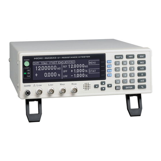
Hioki RM3543 Instruction Manual (226 pages)
RESISTANCE HiTESTER
Brand:
Hioki
| Category:
Test Equipment
| Size: 5 MB
Table of Contents
Table of Contents
3
Task-Oriented Reference
7
Measurement Flow
8
Introduction
9
Verifying Package Contents
9
Safety Information
11
Operating Precautions
13
Chapter 1 Overview
17
Product Overview and Features
17
Block Diagram
20
Names and Functions of Parts
21
Chapter 2 Measurement
21
Screen Organization
23
Connecting the Power Cord
28
Connecting Measurement Cables and Test Fixtures
29
Making Your Own Measurement Cables
30
Turning the Power on and off
32
Chapter 3 Measurement Settings (Basic Measurements)
33
Pre-Operation Inspection
33
Switching 100 M Range Measurement Currents
34
Setting the Measurement Speed
35
Setting Measurement Start Conditions (Trigger Source)
36
Selecting the Measurement Range
37
Zero Adjustment
38
Judging Measured Values (Comparator Function)
40
Enabling and Disabling the Comparator Function
41
Decide According to Reference Value and Tolerance (REF% Mode)
41
Decide According to Upper/Lower Thresholds (ABS Mode)
43
Confirming Faulty Measurements
44
Chapter 4 Customizing Measurement Settings
47
Making Range-Specific Measurement Settings
47
Setting Pre-Measurement Delay
48
Correcting Measured Values (Scaling Function)
50
Setting the Measurement Integration Time Option
52
Stabilizing Measured Values (Averaging Function)
54
Checking for Poor or Improper Contact (Contact Check Function)
55
Improving Probe Contact (Contact Improver Function)
56
Detecting Measurement Voltage Faults (Voltage Level Monitor Function)
58
Applying Current Only When Measuring (Current Mode Setting)
59
Test for Short-Circuited Probe (Probe Short-Circuit Detection Function)
60
Comparing the Measurement Settings of Two Instruments (Settings Monitor Function)
62
Retrying Measurement after a Fault (Retry Function)
65
Maintaining Measurement Precision (Self-Calibration)
66
Compensating for Thermal EMF Offset (Offset Voltage Compensation - OVC)
67
Chapter 5 System Settings
69
Disabling and Enabling Key Operations
69
Disabling Key Operations (Key-Lock Function)
69
Re-Enabling Key Operations (Key-Lock Cancel)
70
Setting the Comparator Decision and Key Beepers
71
Enabling or Disabling the Key Beeper
71
Setting the Comparator Decision ("JUDGE") Beeper
72
Power Line Frequency Manual Setting
73
Setting the Clock
74
Adjusting Screen Contrast
75
Adjusting the Backlight
76
Initializing (Reset)
77
Default Settings
78
Chapter 6 Storing and Exporting Data
79
Storing Data at Specific Times (Data Memory Function)
80
Store as Soon as Measurement Is Stable (Auto-Memory Function)
81
Performing Statistical Calculations on Measured Values
84
Using Statistical Calculations
86
Confirming, Printing, and Erasing Calculation Results
86
Auto-Exporting Measured Values (at End of Measurement) (Data Output Function)
87
Chapter 7 Printing
89
Connecting the Printer
89
Connecting the Printer to the Instrument
90
Instrument Settings
91
Printing
92
Printing Measured Values and Comparator Decisions
92
Printing Statistical Calculation Results
92
Chapter 8 External Control
95
External Input/Output Connector and Signals
95
Connector Type and Signal Pinouts
96
Signal Descriptions
97
Timing Chart
98
Internal Circuitry
100
Electrical Specifications
101
Connection Examples
102
External I/O Settings
103
Setting End-Of-Measurement Signal Output (EOM Signal Setting)
103
Setting the Trigger (TRIG) Signal Logic
104
External Control Q&A
105
Supplied Connector Assembly
106
Chapter 9 Communications
107
Interface)
107
Overview and Features
107
Specifications
108
Connecting
109
Using the RS-232C Interface
110
Using the GP-IB Interface (RM3543-01 Only)
110
Configuring the Communications Protocol
111
Configuring RS-232C Interface Communications
111
Configuring GP-IB Interface Communications (RM3543-01 Only)
112
Select the Measurement Data Transmission Format (both RS-232C and GP-IB)
113
Communication Methods
114
To Cancel the Remote State (Enter the Local State)
114
Message Format
115
Output Queue and Input Buffer
118
Status Byte Register
119
Event Registers
121
Initialization Items
124
Command Execution Time
125
Errors During Communications
125
Message List
126
Standard Commands
126
Device-Specific Commands
127
Message Reference
132
Message Reference Interpretation
132
Device-Specific Commands
137
Data Exporting Methods
158
Sample Programs
160
Using Visual Basic 5.0 or 6.0
160
Sample Programs (Visual Basic 2005)
172
Device Compliance Statement
174
Chapter 10 Specifications
177
Chapter 11 Maintenance and Service
189
Troubleshooting
189
Inspection and Repair
189
Error Displays and Remedies
191
Disposing of the Instrument
193
Removing the Lithium Battery
193
Appendix
195
Appendix 1 Four-Terminal (Voltage-Drop) Method
195
Appendix 2 Effect of Thermal Emf
196
Appendix 3 Unstable Measurement Values.a
197
Appendix 4 Effects of Probing
203
Appendix 5 Rack Mounting
205
Appendix 6 Dimensional Diagram
207
Appendix 7 Calibration
208
Appendix 8 Adjustment Procedure
210
Appendix 9 Table of Commands Compatible with the ADEX AX-1152D
211
Appendix 10Zero Adjustment
213
Index Index
219
Advertisement
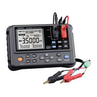
Hioki RM3543 Instruction Manual (168 pages)
Resistance Meter
Brand:
Hioki
| Category:
Measuring Instruments
| Size: 20 MB
Table of Contents
Table of Contents
5
Introduction
9
Verifying Package Contents
10
Safety Notes
12
Usage Notes
15
Handling Precautions
16
1 Overview
23
Overview and Features
23
Overview 15
23
Component Names and Operation Overview
24
X84; Power-On Settings
28
Flow of Measurement
29
Screen Layout
30
Checking the Measurement Target
33
2 Preparing for Measurement
35
Attaching the Strap
36
Loading or Replacing the Batteries
37
Connecting the Test Leads
38
Connecting the Z2002 Temperature Sensor (When Using TC or Δ T)
39
Turning the Power On/Off
40
X84; Turning the Power on
40
X84; Turning the Power off
40
X84; Automatic Power off with Auto Power Save (APS)
41
X84; Disabling Auto Power Save (APS)
41
Pre-Measurement Inspection
42
3 Basic Measurement
43
Setting the Measurement Range
44
Connecting the Test Leads to the Measurement Target
46
Reading the Measured Value
47
X84; Switching the Display
47
X84; Verifying Measurement Errors
48
X84; Holding a Measured Value
50
X84; Memorizing a Measured Value
50
4 Customizing Measurement Conditions
51
Using Zero Adjustment
52
Stabilizing Measured Values (Averaging Function)
57
Compensating for Thermal Effects (Temperature Correction (TC))
58
Compensating for Thermal EMF Offset (Offset Voltage Compensation Function: OVC Function)
59
Setting the Delay Time for Measurement (Delay Function)
61
Switching the Measurement Current (in the 300M Ω Range)
63
5 Judgment and Conversion Functions
67
Judging Measured Values (Comparator Function)
68
X84; Judging Based on Upper and Lower Limit Values (ABS Mode)
71
(REF% Mode)
72
X84; Verifying a Judgment with a Sound (Judgment Sound Function)
73
(L2105 LED Comparator Attachment Option)
74
Performing Temperature Rise Test (Temperature Conversion Function (∆T))
75
Measuring the Length of a Conductor (Length Conversion Function)
77
6 Panel Save and Load (Saving and Loading Measurement Conditions)
79
Saving Measurement Conditions (Panel Save Function)
80
Loading Measurement Conditions (Panel Load Function)
81
Clearing the Contents of a Panel
82
7 Memory Function (Saving and Exporting Measurement Data to a PC)
83
Saving Data at Specified Time (Manual Memory)
85
Saving Data Automatically When Measured
86
Saving Data Automatically When Measured Values Stabilize (Auto-Memory)
86
Saving Data at Fixed Intervals (Interval Memory Function)
87
Displaying Saved Measurement Data (Memory Display Function)
89
Clearing Measurement Data (Memory Clear)
90
Exporting Saved Measurement Data to a PC (USB Mass Storage Mode)
94
8 System Settings
97
Displaying the Date and Time Verification Screen
97
Setting the Clock
98
Initializing (Reset)
99
X84; Default Settings
100
9 Specifications
101
General Specifications
101
X84; Measurement Range
101
X84; Measurement Method
101
X84; Measurement Specifications
101
X84; Accuracy
104
X84; Functions
105
X84; Interface
112
X84; Environmental and Safety Specifications
113
X84; Accessories
113
X84; Options
114
10 Maintenance and Service
115
Troubleshooting
116
X84; Q&A (Frequently Asked Questions and Answers)
116
X84; Error Display and Actions
122
Repair and Inspection
123
Replacing Fuses
124
Disposing of the Instrument
125
Appendix Appx
127
Appx. 1 Block Diagram
127
Appx. 2 Four-Terminal (Voltage-Drop) Method
128
Appx. 3 DC Method and AC Method
129
Appx. 4 Temperature Correction Function (TC)
130
Appx. 5 Temperature Conversion ( Δ T) Function
133
Appx. 6 Effect of Thermoelectromotive Force
134
(Thermal EMF)
134
Appx. 7 Zero Adjustment
137
Appx. 8 Unstable Measurement Values
143
Appx. 9 Locating Short-Circuits on a PC Board
153
Appx. 10 Test Lead Options
154
Appx. 11 Calibration
156
Connection Method
158
Appx. 12 Adjustment
159
Hioki RM3543 Operation Manual (2 pages)
RESISTANCE HiTESTER
Brand:
Hioki
| Category:
Test Equipment
| Size: 0 MB
Advertisement
Advertisement
Related Products
Hioki RM3542
Hioki RM3542-01
Hioki RM3543-01
Hioki RM3544
Hioki RM3544-01
Hioki RM3548
Hioki RM3545
Hioki RM3545-01
Hioki RM3542A Series
Hioki RM3542-51
Hioki Categories
Measuring Instruments
Test Equipment
Data Loggers
Multimeter
Accessories
More Hioki Manuals
Login
Sign In
OR
Sign in with Facebook
Sign in with Google
Upload manual
Upload from disk
Upload from URL