Table of Contents
Advertisement
Quick Links
Advertisement
Table of Contents

Related Manuals for Hioki 8835-01


Summary of Contents for Hioki 8835-01
- Page 1 INSTRUCTION MANUAL 8835-01 MEMORY HiCORDER...
-
Page 3: Table Of Contents
Contents Introduction Inspection Safety Notes Notes on Use Chapter Summary Chapter 1 Product Overview 1.1 Major Features 1.2 Basic and Advanced Versions 1.2.1 Additional Features 1.3 Identification of Controls and Indicators Chapter 2 Installation and Preparation 2.1 Installation of the Unit 2.2 Power Supply and Ground Connection 2.3 Power On/Off 2.4 Probe Connection... - Page 4 3.1.3 JOG/SHUTTLE Control and Select Key 3.1.4 Measurement Start and End 3.1.5 Basic Input Operation 3.1.6 Printer Key Operation 3.1.7 Other Keys Operation 3.1.8 On-line Help 3.2 Basic Measurement and Setting Procedures 3.2.1 Basic Operation Flow 3.2.2 Measuring and Recording a Voltage (Memory Recorder Function) 3.2.3 Measuring and Recording a Voltage (Recorder Function)
- Page 5 4.5 Start and Stop Measurement Operation 4.6 Print Examples Chapter 5 Recorder Function 5.1 Outline 5.1.1 Outline of the Recorder Function 5.1.2 Operation Sequence 5.2 Making Settings 5.2.1 Setting the Function Mode 5.2.2 Setting the Time Axis Range and Sampling 5.2.3 Setting the Recording Length 5.2.4 Setting the Format 5.2.5 Setting the Printer Format...
- Page 6 6.3 Settings on the Display Screen 6.3.1 Setting Compression Along the Time Axis 6.4 Start and Stop Measurement Operation 6.5 Print Examples Chapter 7 Input Channel Settings 7.1 Overview 7.2 Selecting Channels (Memory Recorder Function Only) 7.3 Making the Settings of the 8936 ANALOG UNIT 7.3.1 Setting the Waveform Display Color 7.3.2 Setting the Waveform Display Graph Type 7.3.3 Setting the Voltage Axis Range...
- Page 7 7.7.3 Setting Integral Measurement 7.7.4 Setting for Measuring Pulse Duty Ratio 7.7.5 Setting for Measuring Voltage 7.7.6 Setting for Measuring Current 7.8 Making the Settings of the 8946 4 ch ANALOG UNIT 7.8.1 Settings 7.8.2 Setting the Input Coupling 7.9 Making the Settings of the 8947 CHARGE UNIT 7.9.1 Settings 7.9.2 Setting for Measuring Acceleration 7.9.3 Setting for Measuring Voltage...
- Page 8 Chapter 9 SYSTEM Screen Settings 9.1 Overview 9.2 How to Use the SYSTEM Screen 9.3 Special Function Settings [ SETUP ] 9.3.1 Channel Selection (Memory Recorder Function) 9.3.2 Start Key Backup 9.3.3 Setting the Grid 9.3.4 Channel Marker Function 9.3.5 Displaying the Time from the Trigger Point (Time Display) 9.3.6 List and Gauge Functions 9.3.7 Setting the Printer Density...
- Page 9 9.7.1 Setting the Clock [ TIME SET ] 9.7.2 Clear Waveform Data [ WAVE DATA CLEAR ] 9.7.3 System Reset [ SYSTEM RESET ] 9.8 Self Check 9.8.1 ROM/RAM Check 9.8.2 Printer Check 9.8.3 Display Check 9.8.4 Key Check 9.8.5 PC Card Check Chapter 10 Printout of Waveform Data 10.1 Overview 10.2 Selecting Waveform or Numeric Print...
- Page 10 Chapter 12 External Input/Output Connectors / Key Lock Function 12.1 Overview 12.2 External Start/Stop 12.3 External Printing/Sampling 12.4 Using the External Trigger Input (EXT TRIG) 12.5 Using the External Trigger Output (TRIG OUT) 12.6 Using the Evaluation Outputs (GO), (NG) 12.7 Using the Key Lock Function Chapter 13 Storing, Retrieving and Deleting Waveform Data and Measurement Settings...
- Page 11 14.1.6 Others 14.2 Trigger Unit 14.3 Memory Recorder Function 14.4 Recorder Function 14.5 RMS Recorder Function 14.6 Recorder & Memory Function (Advanced Version) 14.7 FFT Function (Advanced Version) 14.8 Advanced Version 14.9 Auxiliary Function 14.10 Others 14.11 9439 DC POWER ADAPTER Specifications 14.12 System Operation Chapter 15 Logic and Analog Inputs 15.1 Logic Inputs...
- Page 12 Chapter 16 Maintenance 16.1 Printer Head Cleaning 16.2 Removing the Battery Before Discarding the 8835-01 16.3 Troubleshooting 16.4 Cleaning the Unit 16.5 Service Appendix APPENDIX1 Appendix 1 Error and Warning Messages APPENDIX1 Appendix 1.1 Error Messages APPENDIX2 Appendix 1.2 Warning Messages...
-
Page 13: Introduction
──────────────────────────────────────────────────── Introduction Thank you for purchasing this HIOKI "8835-01 MEMORY HiCORDER." To get the maximum performance from the unit, please read this manual first, and keep this at hand. Inspection ・When the unit is delivered, check and make sure that it has not been damaged in transit. - Page 14 ──────────────────────────────────────────────────── Options 9540-01 FUNCTION UP DISK 8936 ANALOG UNIT 8937 VOLTAGE/TEMP UNIT 8938 FFT ANALOG UNIT 8939 STRAIN UNIT 8940 F/V UNIT 8946 4 ch ANALOG UNIT 8947 CHARGE UNIT 9439 DC POWER ADAPTER 9221 RECORDING PAPER (10 rolls) 9557 RS-232C CARD 9558 GP-IB CARD 9559 PRINTER CARD 9333 LAN COMMUNICATOR...
-
Page 15: Safety Notes
──────────────────────────────────────────────────── Safety Notes This product is designed to conform to IEC 61010 Safety Standards, and DANGER has been thoroughly tested for safety prior to shipment. However, mishandling during use could result in injury or death, as well as damage to the product. Be certain that you understand the instructions and precautions in the manual before use. - Page 16 ──────────────────────────────────────────────────── Conventions used in this manual The following symbols are used in this Instruction Manual to indicate the relative importance of cautions and warnings. Indicates that incorrect operation presents extreme danger of DANGER accident resulting in death or serious injury to the user. Indicates that incorrect operation presents significant danger of WARNING accident resulting in death or serious injury to the user.
-
Page 17: Notes On Use
・Check that the power supply is correct for the rating of the unit. (The AC fuse is integrated in the unit.) ・The AC power power switch on 8835-01 is for AC power. If DC power is being supplied and the switch on DC power adapter is set to ON, the 8835- 01 will operate also if the power switch is set to OFF. - Page 18 VOLTAGE/TEMP UNIT, 8938 FFT ANALOG UNIT, 8939 STRAIN UNIT 8940 F/V UNIT, 8946 4ch ANALOG UNIT, 8947 CHARGE UNIT and input terminals of the 8835-01 are shown below. To avoid the risk of electric shock and damage to the unit, take care not to exceed these ratings.
- Page 19 Logic probe input and 8835-01 share the same GND. Separate power DANGER supply sources applied to the testing device and 8835-01 may result in risk of electric shock and damage to the unit. Even with the same power supply source, certain ways of wiring may cause a variance in electric potential sending current that may damage testing device and 8835-01.
- Page 20 Before using the product, make sure that the insulation on the cords and WARNING probes is undamaged and that no bare conductors are improperly exposed. Using the product under such conditions could result in electrocution. Replace the cords and probes specified by HIOKI. ──────────────────────────────────────────────────── Notes on Use...
-
Page 21: Chapter Summary
──────────────────────────────────────────────────── Chapter Summary Chapter 1 Product Overview Contains an overview of the unit and its features. Chapter 2 Setup and Preparations Explains how to set the unit up for measurement. Chapter 3 Operation Steps for Basic Measurement Explains how to operate the keys and JOG/SHUTTLE control for carrying out basic measurement functions. - Page 22 ──────────────────────────────────────────────────── Chapter 13 Storing, Recalling and Deleting Waveform Data and Measurement Settings Explains how to store, recall, and delete waveform data and measurement settings. Chapter 14 Specifications Contains general specifications and detailed function specifications. Chapter 15 Logic Input Section and Analog Input Unit Contains specifications and precautions for logic input section and input amplifier units.
-
Page 23: Chapter 1 Product Overview
──────────────────────────────────────────────────── Chapter 1 Product Overview 1.1 Major Features (1) Easy to read, TFT color display The 6.4-inch TFT color screen with a resolution of 640 × 480 dots shows all information at a glance. (2) Three functions to meet a huge range of applications ・Memory recorder with up to 1 μs (all channels simultaneously) (1 MS/s) ・Real-time recording capability to paper in recorder function ・RMS recorder function for recording rms values of AC power supply lines and... - Page 24 The analog inputs are floating, and so each input can be connected to its own independent potentials. (11) Portable The 8835-01 weighs only 4.5 kg and has an A4-size form factor, making it extremely portable. (12) Floppy disk, PC card (external storage) Waveform data and measurement settings can be stored on floppy disk or PC card.
- Page 25 (1) Frequency, (2) Count, (3) Pulse duty ratio, (4) Voltage (5) Current (3) Eight times the memory capacity of the 8835 The installed memory capacity of the 8835-01 is eight times that of the 8835. 8835 Installed Memory: 500K words (expandable to 2M words)
-
Page 26: Basic And Advanced Versions
──────────────────────────────────────────────────── 1.2 Basic and Advanced Versions This section explains the features of the basic version and the advanced version. It is possible to upgrade the basic version to the advanced version, using the feature upgrade disk available as an option. 1.2.1 Additional Features The following features and functions can be added to the basic version. - Page 27 ──────────────────────────────────────────────────── Memory segmentation function Memory can be segmented among channels. (255 segments) Sequential save function This function does not update the display indication or record data on the printer or external storage. Input signal capture is carried out continuously using the trigger. Multi-block function Waveform data can be stored in a selected block.
-
Page 28: Identification Of Controls And Indicators
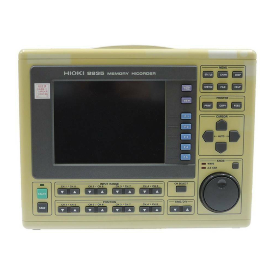
──────────────────────────────────────────────────── 1.3 Identification of Controls and Indicators Controls and indicators of the unit are listed on the following pages, along with a simple explanation of their function. Front panel Causes the display to show the STATUS screen which STATUS serves for setting most measurement parameters. Causes the display to show the CHANNEL screen which CHAN serves for making input channel settings. - Page 29 ──────────────────────────────────────────────────── Provides on-line help. HELP Serves to print out stored waveforms. PRINT Serves to print out a hard copy of the current screen COPY display. Causes the printer paper to advance for as long as the FEED key is pressed. These keys serve to move the flashing cursor in the four keys CURSOR...
- Page 30 ──────────────────────────────────────────────────── Left side view 11 12 Right side view ──────────────────────────────────────────────────── 1.3 Identification of Controls and Indicators...
- Page 31 Can be used to synchronize multiple units, using the EXT TRIG input and TRIG OUT output. When this switch is set to ON, all keys of the 8835-01 KEY LOCK switch are inactive. The key lock condition is maintained also when the power is switched off and on again.
- Page 32 ──────────────────────────────────────────────────── Top view Bottom view Ventilation slots Serves for transporting the 8835-01. Handle Logic probe connectors Input connector for the logic input section, designed for the dedicate logic probes (CH A, CH B, CH C, CH D). Ventilation slots Tilt support ────────────────────────────────────────────────────...
-
Page 33: Chapter 2 Installation And Preparation
──────────────────────────────────────────────────── Chapter 2 Installation and Preparation ────────────────────────────────────────────────────... -
Page 34: Installation Of The Unit
──────────────────────────────────────────────────── 2.1 Installation of the Unit Installation orientation Install the unit on a flat, level surface. The unit can also be propped up at an angle, using the stand. ──────────────────────────────────────────────────── 2.1 Installation of the Unit... - Page 35 ──────────────────────────────────────────────────── Ambient conditions Temperature 5 to 40℃, 23±5℃ recommended for high-precision measurements 35 to 80%RH (no condensation); 50±10%RH (no Humidity condensation) recommended for high-precision measurements Ventilation Take care not to block the ventilation openings and assure proper ventilation. When using the unit in an upright position, take care not to block the openings on the bottom, as it could overheat and be damaged, or cause a fire.
-
Page 36: Power Supply And Ground Connection
Check the following points before connecting the unit to a power supply: ・The power supply matches the ratings shown above. ・The AC power switch of the 8835-01 and the switch of the 9439 DC POWER ADAPTER are set to OFF. - Page 37 (1) AC power supply WARNING Make sure that the AC power switch of the 8835-01 is set to OFF. 1. Verify that the AC power switch of the 8845 is set to OFF. 2. Plug the grounded three-core power cord supplied into the AC power connector on the right side of the 8835-01.
- Page 38 Before making connections, make sure the 9439 DC POWER ADAPTER WARNING is turned off. The 8835-01 could be damaged by a spark if it is connected to a voltage source while its power supply is on. The rated supply voltage of the 9439 DC POWER ADAPTER is 10 to 28 VDC.
- Page 39 ──────────────────────────────────────────────────── Rated voltage: 10 to 28 V DC ・ This unit is not equipped to charge an external battery. NOTE ・ When using a battery, take care not to deplete it completely. ・ When an overcurrent or overvoltage is detected in the output, this equipment cuts off the output.
-
Page 40: Power On/Off
・There is no need for the user to manually select AC or DC power. ・When both AC and DC power are connected, AC power has priority. ・When AC power is disconnected (or falls under 90 V), the 8835-01 automatically switches to DC. (If the switch of the 9439 is set to ON, the 8835-01 automatically switches to DC even if AC power is disconnected.) -
Page 41: Probe Connection
2.4 Probe Connection 2.4.1 8936 ANALOG UNIT, 8938 FFT ANALOG UNIT and 8946 4 ch ANALOG UNIT Never connect the probe to the 8835-01 while the probe is already WARNING connected to the measurement object. Otherwise there is a risk of electric shock. -
Page 42: 8937 Voltage/Temp Unit
1,2,3,4. Channel number is determined by connection to units. (See below.) To verify position of channels, see Channel Guide. 2.4.2 8937 VOLTAGE/TEMP UNIT Never connect the connection cable to the 8835-01 while the connection WARNING cable is already connected to the measurement object. Otherwise there is a risk of electric shock. - Page 43 ──────────────────────────────────────────────────── Thermocouple connection (Temperature measurement) 1. Strip off the insulation as shown in the illustration. 25 mm Outer insulation (mantle) 10 mm Thermocouple leads Inner insulation 2. Push the tab with a screwdriver or similar. 3. While keeping the tab depressed, insert a stripped thermocouple into the connector openings.
-
Page 44: 8939 Strain Unit
──────────────────────────────────────────────────── 2.4.3 8939 STRAIN UNIT ・Connect only the sensor to the conversion cable supplied with the 8939 CAUTION STRAIN UNIT. ・To disconnect the conversion cable, always unlock the plug and pull out the cable. Connecting to the main unit 1. Align the projection on the unit connector with the cutout on the conversion cable, and insert the plug into the connector. -
Page 45: 8940 F/V Unit
──────────────────────────────────────────────────── 2.4.4 8940 F/V UNIT To avoid electrical accidents, make sure that the MEMORY HiCORDER DANGER and the equipment being measured are powered off before making connections. Do not make connections with the power turned on. When using the 9318 or 9319 CONVERSION CABLE, there is no isolation between GND the MEMORY HiCORDER and GND of the clamp on sensor/probe. - Page 46 ──────────────────────────────────────────────────── Connecting to 9318 CONVERSION CABLE 1. Align the groove on the conversion cable plug with the sensor connector on the F/V unit and push inward until the connector locks into place. 2. Align the groove on the conversion cable connector with the adapted clamp on sensor plug and push inward until the connector locks into place.
-
Page 47: 8947 Charge Unit
──────────────────────────────────────────────────── 2.4.5 8947 CHARGE UNIT DO NOT connect connection cable to the 8947 CHARGE UNIT when WARNING connected to measuring unit to avoid risk of electric shock. BNC terminal and miniature connecter terminal of each channel share same GND. Do not connect both at once. During measuring with measurement mode set to PREAMP or when level monitor function is in use, electric current (2 mA, +15 V) output is active. -
Page 48: Logic Probe Connection
Logic probe input and 8835-01 share the same GND. Separate power DANGER supply sources applied to the testing device and 8835-01 may result in risk of electric shock and damage to the unit. Even with the same power supply source, certain ways of wiring may cause a variance in electric potential sending current that may damage testing device and 8835-01. -
Page 49: 9322 Differential Probe Connection
9322 is a differential probe that connects to input of 8835-01 MEMORY HiCORDER input unit. For more details, refer to its instruction manual. - Page 50 ──────────────────────────────────────────────────── 2. Raise the head up/down lever. Head up/down lever Printer exit slot 3. Insert the attachments into the ends of the roll of recording paper and set the paper into its holder. Holder 9221 Attachment RECORDING PAPER 4. Insert the leading edge of the recording paper from above into the gap behind the printer roller, and pull it out to the other side.
- Page 51 ──────────────────────────────────────────────────── 7. Pull the recording paper to the outside through the printer exit slot in the stock cover. Head up/down lever 8. Close the stock cover, and finish by tearing off the recording paper against the edge of the printer exit slot. ・...
-
Page 52: Storage And Handling Precautions
──────────────────────────────────────────────────── 2.8 Storage and Handling Precautions Store rolls of thermal paper at no more than 40℃. The paper will change color if exposed to light over a long period, so do not unwrap a roll of paper until you are ready to use it. Storing data recordings As the recording paper is thermally sensitive, be aware of the following points: ・To avoid paper discoloration, do not expose it to direct sunlight, and store at... -
Page 53: Notes On Measurement
VOLTAGE/TEMP UNIT, 8938 FFT ANALOG UNIT, 8939 STRAIN UNIT 8940 F/V UNIT, 8946 4ch ANALOG UNIT, 8947 CHARGE UNIT and input terminals of the 8835-01 are shown below. To avoid the risk of electric shock and damage to the unit, take care not to exceed these ratings. - Page 54 Using the product under such conditions could result in electrocution. Replace the connection cords with the specified HIOKI Model 9197 or 9198. ・When making measurements on an AC power line for example, using a...
-
Page 55: Using A Voltage Transformer
When making measurements on an AC power line for example, using a voltage transformer, be sure to connect the voltage transformer ground terminal to ground. When the voltage transformer has a ground terminal 8936 or H 8835-01 8938 L GND terminal Input Voltage transformer... - Page 56 ──────────────────────────────────────────────────── 8940 F/V UNIT 8835-01 Sensor 30 Vrms or 60 VDC connector L 8940 30 Vrms or DC60 V 30 Vrms or L 60 VDC 30 Vrms or DC60 V 8947 CHARGE UNIT 8835-01 BNC H 30 Vrms or 60 VDC L...
-
Page 57: Chapter 3 Basic Operation And Measurement
──────────────────────────────────────────────────── Chapter 3 Basic Operation and Measurement 3.1 Basic Operation This section explains basic steps and settings for measurement. 3.1.1 Basic Display Operation STATUS key CHAN key DISP key HELP key SYSTEM key FILE key Calls up the STATUS screen. STATUS Serves to switch pages of the STATUS screen. -
Page 58: Setting Items
──────────────────────────────────────────────────── Calls up the SYSTEM screen. SYSTEM Serves to switch pages of the SYSTEM screen. Serves to make common settings for all functions (clock setting, comment input, etc.) on the SYSTEM screen. On-line help HELP An explanation of the display screen or the item currently selected by the cursor appears. -
Page 59: Jog/Shuttle Control And Select Key
──────────────────────────────────────────────────── 3.1.3 JOG/SHUTTLE Control and Select Key LEDs Select key Jog control Shuttle control Entering numbers and setting items (except on the DISPLAY screen) Function key display (GUI) Move the flashing item selection cursor up in Value up the selection window. Value down Move the flashing item selection cursor down in the selection window. -
Page 60: Measurement Start And End
──────────────────────────────────────────────────── 3.1.4 Measurement Start and End START key STOP key Measure Press the key and the LED lights. START Stop measurement Press the key and the LED goes out after measurement has finished. STOP 3.1.5 Basic Input Operation INPUT RANGE keys CH SELECT key TIME/DIV key POSITION keys... -
Page 61: Printer Key Operation
──────────────────────────────────────────────────── 3.1.6 Printer Key Operation PRINT key COPY key FEED key PRINT Serves to print the waveform. The output destination by this key can be selected. COPY Produces a hard copy of the display content. The output destination by this key can be selected. - Page 62 ──────────────────────────────────────────────────── 〔When the recording length is 100 divisions〕 Trigger position A cursor B cursor ・Time axis magnification ratio: × 1 Displyed part (10 divisions) ・Time axis magnification ratio: × 2 Displyed part ・Time axis magnification ratio: × 1/2 Displyed part Shifting the display position The new waveform display position can be Upper limit value of the displayed channel...
-
Page 63: On-Line Help
──────────────────────────────────────────────────── 2. Back Space Back Space is used for backspacing when comments are input. 3. Channel guide Indicates channels for specific position of input units (see Section 7.14). 4. List print Prints file list displayed on the file screen to output destination designated by key (see Section 9.6.2). -
Page 64: Basic Measurement And Setting Procedures
──────────────────────────────────────────────────── 3.2 Basic Measurement and Setting Procedures This section uses some representative examples to describe basic measurement steps and settings. 3.2.1 Basic Operation Flow The basic operation flow is shown below. Panel key Setting screen Setting item Description STATUS Status 1 Time axis Sets data capture Various... -
Page 65: Measuring And Recording A Voltage
1 kHz sine wave input is measured. (1) Input connection Connect a signal generator to the 8835-01. (2) Set the signal generator so that it outputs a 2 Vp-p 1 kHz sine wave. (3) Settings on the STATUS 1 screen Make the following settings with the CURSOR keys and function keys. - Page 66 ──────────────────────────────────────────────────── (5) Settings on the CHANNEL 1 screen Make the following settings with the CURSOR keys and function keys. range: 500 mV/DIV zoom: 1 zero position: 50% low-pass filter: OFF (6) Measurement ・Press the key, and the LED above the key lights.
- Page 67 1 Hz sine wave input is measured. (1) Input connection Connect a signal generator to the 8835-01. (2) Set the signal generator so that it outputs a 2 Vp-p 1 Hz sine wave. (3) Settings on the STATUS 1 screen Make the following settings with the CURSOR keys and function keys.
- Page 68 ──────────────────────────────────────────────────── (5) Settings on the CHANNEL 1 screen Make the following settings with the CURSOR keys and function keys. range: 500 mV/DIV zoom: 1 zero position: 50% low-pass filter: OFF (6) Measurement ・Press the key, and the LED above the key lights.
-
Page 69: (Rms Recorder Function)
Example A signal going below 5 Vrms is captured. (1) Input connection Connect a signal generator to the 8835-01. (2) Set the signal generator so that it outputs a sine wave of 50 Hz and 5 Vrms or more. (3) Settings on the STATUS 1 screen Make the following settings with the CURSOR keys and function keys. - Page 70 ──────────────────────────────────────────────────── (5) Settings on the CHANNEL 1 screen Make the following settings with the CURSOR keys and function keys. range: 1 V/DIV zoom: 1 zero position: 0% low-pass filter: OFF (6) Measurement ・Press the key, and the LED above the key lights.
-
Page 71: Chapter 4 Memory Recorder Function
──────────────────────────────────────────────────── Chapter 4 Memory Recorder Function 4.1 Outline 4.1.1 Outline of the Memory Recorder Function The memory recorder function has the following features. (1) After being stored in the internal memory, input signal data can be displayed and printed. (2) All input channel data are recorded on the same time axis. Since data for all channels can be superimposed, the relative relationship between input signals can be observed visually. -
Page 72: Operation Sequence
──────────────────────────────────────────────────── 4.1.2 Operation Sequence The flowchart below illustrates the sequence of operations involved in using the memory recorder function. Turn on the power. Start Connect the inputs. Select the memory recorder function. Select function. Status 1 screen Set the time axis range Determine the speed with which the input (TIME/DIV). -
Page 73: Making Settings
──────────────────────────────────────────────────── 4.2 Making Settings 4.2.1 Setting the Function Mode The 8835-01 has three function modes: the memory recorder function mode, the recorder function mode, and the RMS recorder function mode. Select the memory recorder function. Method Screen: STATUS 1, 2, CHANNEL, DISPLAY 1. -
Page 74: Setting The Time Axis Range
──────────────────────────────────────────────────── 4.2.2 Setting the Time Axis Range ・Set the speed for inputting and storing the waveform of the input signal. ・Time axis range setting expresses the time for 1 DIV. ・The sampling period is 1/100th of the set value for the time axis range. (100 samples/DIV) ・When external sampling is set, sampling is performed in synchronization with an external signal. -
Page 75: Setting The Recording Length
──────────────────────────────────────────────────── Data points per division are set when external sampling is selected. 1. Move the flashing cursor to the samples/DIV item, as shown in the figure on the left. 2. Use the control or the function JOG/SHUTTLE keys to make the selection. Setting range is 10 to 1000. - Page 76 ──────────────────────────────────────────────────── NOTE ・Depending on the number of channels, the recording length is limited (see Section 14.3). (For setting the number of channels, see Section 9.3.1.) ・On the DISPLAY screen, the selection window is not displayed. Method 2 (Any recording length mode) Screen: STATUS 1, DISPLAY 1.
-
Page 77: Setting The Format
──────────────────────────────────────────────────── 4.2.4 Setting the Format ・The style can be set for showing input signals on the screen display and recording them on the printer. ・The styles single, dual, quad, X-Y (dot), and X-Y (line) are available. (1) Single Display and record as one graph. (At the most, 8 analog + 16 logic signals) Input waveform (2) Dual ・Display and record as two graphs. - Page 78 ──────────────────────────────────────────────────── (4) X-Y (dot), (line) Assign any analog channel to the X axis and the other seven channels to the Y axis to form the combined plot. Method Screen: STATUS 1 1. Call up the STATUS 1 screen. 2. Move the flashing cursor to the format item, as shown in the figure on the left.
-
Page 79: Using The X-Y Waveform Plots
──────────────────────────────────────────────────── 4.2.5 Using the X-Y Waveform Plots ・Setting the display format to X-Y in Section 4.2.4 allows X-Y waveforms to be combined. ・Assign any analog channel to the X axis and the other seven channels to the Y axis to form the combined plot. ・Voltage axis magnification/compression is active also when using X-Y combined plotting. - Page 80 ──────────────────────────────────────────────────── Method 1. Call up the STATUS 1 screen. 2. Move the flashing cursor to the format item. 3. Use the function keys to select X-Y (dot) or X-Y (line). 4. Press the key to call up the CHAN CHANNEL 1 screen. 5.
-
Page 81: Setting The Printer Format
──────────────────────────────────────────────────── 4.2.6 Setting the Printer Format ・Selects whether waveform data are printed as waveform or as numeric data. ・When numeric data are selected, the print interval also must be set. Printing as a waveform Method 1. Press the key to call up the STATUS STATUS 1 screen. - Page 82 ──────────────────────────────────────────────────── Printing as numeric data Method 1. Press the key to call up the STATUS STATUS 1 screen. 2. Move the flashing cursor to the print mode item, as shown in the figure on the left. 3. Use the function keys to select numeric data. : Waveform data and the result of calculation are printed as a waveform.
-
Page 83: Setting The Roll Mode
──────────────────────────────────────────────────── 4.2.7 Setting the Roll Mode ・This mode can be used at a time axis range setting of 10 ms/DIV or slower. ・When roll mode is set to ON, the waveform is displayed immediately at the start of recording (the screen scrolls). Method 1. -
Page 84: Setting The Auto Save Function
──────────────────────────────────────────────────── 4.2.9 Setting the Auto Save Function When the function is enabled, waveform data are automatically stored on a floppy disk or PC card after they are captured. Method 1. Press the key to call up the STATUS STATUS 1 screen. 2. - Page 85 : Data are stored as binary data. : Data are stored as text data. NOTE The TEXT format is intended for reading by a PC. Select BINARY for reading by the 8835-01. 7. Selected TEXT in save options opens Thinning. Use the control or the function keys to make the selection.
-
Page 86: Overlay
──────────────────────────────────────────────────── 4.2.10 Overlay ・Overlay is performed without clearing the currently displayed waveform (if trigger mode is REPEAT or AUTO). ・This allows comparison to the immediately preceding waveform. Method Screen: STATUS 1 1. Move the flashing cursor to the overlay item. 2. -
Page 87: Setting The Trigger
──────────────────────────────────────────────────── 4.2.11 Setting the Trigger Select the trigger that is suitable for the signal to be captured. For details, see Chapter 8. 4.2.12 Input Channel Settings The settings differ for each unit. See the settings for each unit in Chapter 7. ────────────────────────────────────────────────────... -
Page 88: Settings On The Display Screen
──────────────────────────────────────────────────── 4.3 Settings on the Display Screen Explains the setting items on the Display screen and the setting of the voltage axis and time axis. 4.3.1 Setting Magnification/Compression Along the Time Axis ・The magnification/compression ratio along the time axis can be set. ・By magnifying the waveform, detailed observations can be made. -
Page 89: Automatic Setting Of Time Axis And Voltage Axis
──────────────────────────────────────────────────── 4.3.2 Automatic Setting of Time Axis and Voltage Axis (Auto Range Function) This function automatically selects the time axis range, voltage axis range and zero position. Method Screen: DISPLAY 1. Press the cursor keys simultaneously. 2. Use the function keys to execute or cancel the function. ・Because the auto-range function performs automatic setting for the input NOTE signal present at the time the function is executed, input a signal before... -
Page 90: Summary Of The Processing Functions
──────────────────────────────────────────────────── 4.4 Processing Functions (Waveform Parameter Processing) 4.4.1 Summary of the Processing Functions ・The function is available only when using the memory recorder function. ・The following 14 processing functions are available for the captured waveform data. ・Processing results are shown in numerical form. ・If the A/B cursors are turned off, processing is carried out for all data. -
Page 91: Processing Method
──────────────────────────────────────────────────── 4.4.2 Processing Method Settings for the processing method are made with the status 3 screen. Method Screen: STATUS 3 1. Call up the STATUS 3 screen. 2. Move the flashing cursor to the point shown in the figure on the left. 3. - Page 92 ──────────────────────────────────────────────────── 6. Move the flashing cursor to the point shown in the figure on the left, and enable or disable storing of parameter processing results. Use the function keys to make the selection. : Processing results are not stored. : Processing results are stored on floppy disk. : Processing results are stored on PC card.
-
Page 93: Waveform Parameter Calculation Details
──────────────────────────────────────────────────── 4.4.3 Waveform Parameter Calculation Details (1) Average value ・Calculates the average value (V) of the waveform data. ・Equation: AVE: average value n: number of data samples : i-th data of the source channel (2) RMS value ・Calculates the RMS (effective) value (V) of the waveform data. ・When scaling is used, the value is calculated after scaling. - Page 94 ──────────────────────────────────────────────────── (7) Time to minimum value ・Calculates the time interval from the triggering point to the minimum value of the waveform (in seconds). ・If there are two minimum value points, the time to the first point is calculated. (8) Period (9) Frequency ・Displays the period (s) and frequency (Hz) of the signal waveform.
- Page 95 ──────────────────────────────────────────────────── (12) Standard deviation ・Calculates the standard deviation (V) of the waveform data. ・Equation: σ: standard deviation AVE: average value n: number of data samples : i-th data of the source channel (13) Area value ・Calculates the area bordered by the signal waveform and the zero position (potential 0 V).
- Page 96 ──────────────────────────────────────────────────── (14) X-Y area value ・Calculates the area (V ) after X-Y plotting. ・The waveform is plotted on the X-Y screen, and the area enclosed by the plot lines is calculated. ・In single, dual, or quad screen, the A/B cursors (vertical, trace) can be used to specify the range for X-Y plotting and area calculation.
-
Page 97: Start And Stop Measurement Operation
STOP displayed and printed out, and measurement is stopped. When the key is pressed twice, the 8835-01 is forcibly stopped. STOP ・When measurement is forcibly stopped following trigger generation, waveform data collected up to the point of termination remains after measurement is stopped. -
Page 98: Print Examples
──────────────────────────────────────────────────── 4.6 Print Examples Single screen (The list and gauge functions are enabled.) Dual screen (The gauge function is enabled.) Quad screen (The gauge function is enabled.) ──────────────────────────────────────────────────── 4.6 Print Examples... - Page 99 ──────────────────────────────────────────────────── Report List Numeric data ──────────────────────────────────────────────────── 4.6 Print Examples...
- Page 100 ──────────────────────────────────────────────────── (The gauge function is enabled.) ──────────────────────────────────────────────────── 4.6 Print Examples...
-
Page 101: Recorder Function
──────────────────────────────────────────────────── Chapter 5 Recorder Function 5.1 Outline 5.1.1 Outline of the Recorder Function The recorder function has the following features. (1) Real time display and printing of the input signal (2) Real time continuous recording of the input signal (3) All input channel data are recorded on the same time axis. Since data for all channels can be superimposed, the relative relationship between input signals can be observed visually. -
Page 102: Operation Sequence
──────────────────────────────────────────────────── 5.1.2 Operation Sequence The flowchart below illustrates the sequence of operations involved in using the recorder function. Turn on the power. Start Connect the inputs. Select the recorder function. Select function. Status 1 screen Set the time axis range Determine the speed with which the input (TIME/DIV). -
Page 103: Making Settings
──────────────────────────────────────────────────── 5.2 Making Settings 5.2.1 Setting the Function Mode The 8835-01 has three function modes: the memory recorder function mode, the recorder function mode, and the RMS recorder function mode. Select the recorder function. Method Screen: STATUS 1, 2, CHANNEL, DISPLAY 1. -
Page 104: Setting The Time Axis Range And Sampling
──────────────────────────────────────────────────── 5.2.2 Setting the Time Axis Range and Sampling ・Set the speed for inputting and storing the waveform of the input signal. ・Time axis range setting expresses the time for 1 DIV. ・Sampling period settings start at 1 μs (and range up to a maximum of 1 MS/s). - Page 105 ──────────────────────────────────────────────────── Method 2 Screen: STATUS 1, DISPLAY 1. Call up the STATUS 1 or DISPLAY screen. 2. Use the key to set the time axis range. TIME/DIV ・The key can be used regardless of where the flashing cursor is TIME/DIV NOTE located, if the STATUS 1 or DISPLAY screen is displayed.
-
Page 106: Setting The Recording Length
──────────────────────────────────────────────────── 5.2.3 Setting the Recording Length ・The length of recording for one measurement operation (number of DIV) can be set. ・Two types of recording length can be set. Fixed recording length mode: Any recording length mode: Any recording length can be selected by the user. Method 1 (Fixed recording length mode) Screen: STATUS 1, DISPLAY 1. - Page 107 ──────────────────────────────────────────────────── Method 2 (Any recording length mode) Screen: STATUS 1, DISPLAY 1. Call up the STATUS 1 or DISPLAY screen. 2. Move the flashing cursor to the shot item, as shown in the figure on the left. 3. Set the any recording length mode. 4.
-
Page 108: Setting The Format
──────────────────────────────────────────────────── 5.2.4 Setting the Format ・The style can be set for showing input signals on the screen display and recording them on the printer. ・The styles single, dual, and quad are available. (1) Single Display and record as one graph. (At the most, 8 analog + 16 logic signals) Input waveform (2) Dual ・Display and record as two graphs. - Page 109 ──────────────────────────────────────────────────── Method Screen: STATUS 1 1. Press the key to call up the STATUS STATUS 1 screen. 2. Move the flashing cursor to the format item, as shown in the figure on the left. 3. Use the function keys to select the display format.
- Page 110 ──────────────────────────────────────────────────── Continuous X-Y plot ・Setting the display format to X-Y allows X-Y waveforms to be combined continuously. ・Selecting the X-Y display format changes the setting screen as shown in the figure below. 1. Use the function keys to select the display format.
-
Page 111: Setting The Printer Format
──────────────────────────────────────────────────── 5.2.5 Setting the Printer Format ・Selects whether waveform data are printed as waveform or as numeric data. ・When numeric data are selected, the print interval also must be set. Printing as a waveform Method 1. Press the key to call up the STATUS STATUS 1 screen. - Page 112 ──────────────────────────────────────────────────── Printing as numeric data Method 1. Press the key to call up the STATUS STATUS 1 screen. 2. Move the flashing cursor to the print mode item, as shown in the figure on the left 3. Use the function keys to select numeric data. : Waveform data are printed as a waveform.
-
Page 113: Setting The Additional Recording Function
──────────────────────────────────────────────────── 5.2.6 Setting the Additional Recording Function ・This records, regarding the memory as though it were recording paper. ・The last 2000 divisions of waveform can be held in memory. ・The waveform can be scrolled and printed. Switching the additional recording on and off affects the use of memory as shown below. -
Page 114: Setting The Printer Function (Real Time Printing)
──────────────────────────────────────────────────── Method 1. Press the key to call up the STATUS STATUS 1 screen. 2. Move the flashing cursor to the additional recording item, as shown in the figure on the left 3. Use the function keys to make the selection. : Additional recording is disabled. -
Page 115: Setting The Auto Save Function
──────────────────────────────────────────────────── 5.2.8 Setting the Auto Save Function When the function is enabled, waveform data are automatically stored on a floppy disk or PC card after they are captured. Method 1. Press the key to call up the STATUS STATUS 1 screen. 2. -
Page 116: Setting The Trigger
: Data are stored as text data. NOTE ・Data stored in the text format is not readable by the 8835-01. ・When the characters below are used in a file, the file cannot be handled on a PC running Windows 2000 or XP. Do not use these characters when handling a file on your PC. -
Page 117: Settings On The Display Screen
──────────────────────────────────────────────────── 5.3 Settings on the Display Screen Explains the setting items on the Display screen. 5.3.1 Setting Compression Along the Time Axis ・The compression ratio along the time axis can be set. ・By compressing the waveform, an entire change can be promptly apprehended. 6-19 Method 1. -
Page 118: Start And Stop Measurement Operation
──────────────────────────────────────────────────── 5.4 Start and Stop Measurement Operation Method 1. Press the key to initiate measurement or set the unit to trigger START standby. 2. Press the key during measurement to stop the measurement. STOP (see Section 3.1.4.) Lights during measurement ────────────────────────────────────────────────────... -
Page 119: Print Examples
──────────────────────────────────────────────────── 5.5 Print Examples Single screen (The list and gauge functions are enabled.) Dual screen (The gauge function is enabled.) Quad screen (The gauge function is enabled.) ──────────────────────────────────────────────────── 5.5 Print Examples... - Page 120 ──────────────────────────────────────────────────── Report List Numeric data ──────────────────────────────────────────────────── 5.5 Print Examples...
-
Page 121: Chapter 6 Rms Recorder Function
(1) The voltage value and DC signal for the commercial power supplies are displayed and recorded as the rms value. (2) Real time continuous recording (3) The 8835-01 is designed to measure commercial power supplies (50/60 Hz) and DC signal. (4) Time axis setting... -
Page 122: Operation Sequence
──────────────────────────────────────────────────── 6.1.2 Operation Sequence The flowchart below illustrates the sequence of operations involved in using the RMS recorder function. Turn on the power. Start Connect the inputs. Select function. Select the RMS recorder function. Status 1 screen Set the time axis range Determine the speed with which the (TIME/DIV). -
Page 123: Making Settings
──────────────────────────────────────────────────── 6.2 Making Settings 6.2.1 Setting the Function Mode The 8835-01 has three function modes: the memory recorder function mode, the recorder function mode, and the RMS recorder function mode. Select the RMS recorder function. Method Screen: STATUS 1, 2, CHANNEL, DISPLAY 1. -
Page 124: Setting The Time Axis Range
──────────────────────────────────────────────────── 6.2.2 Setting the Time Axis Range ・Set the speed for inputting and storing the waveform of the input signal. ・Time axis range setting expresses the time for 1 DIV. ・The sampling interval is constant, regardless of the time axis range. Method 1 Screen: STATUS 1, DISPLAY 1. -
Page 125: Setting The Frequency
──────────────────────────────────────────────────── 6.2.3 Setting the Frequency Serves to set the frequency of the signal to be measured. Method 1. Press the key to call up the STATUS STATUS 1 screen. 2. Move the flashing cursor to the frequency item, as shown in the figure on the left. 3. -
Page 126: Setting The Recording Length
──────────────────────────────────────────────────── 6.2.4 Setting the Recording Length ・The length of recording for one measurement operation (number of DIV) can be set. ・Two types of recording length can be set. Fixed recording length mode: Any recording length mode: Any recording length can be selected by the user. Method 1 (Fixed recording length mode) Screen: STATUS 1, DISPLAY 1. - Page 127 ──────────────────────────────────────────────────── Method 2 (Any recording length mode) Screen: STATUS 1, DISPLAY 1. Call up the STATUS 1 or DISPLAY screen. 2. Move the flashing cursor to the shot item, as shown in the figure on the left. 3. Set the any recording length mode. 4.
-
Page 128: Setting The Format
──────────────────────────────────────────────────── 6.2.5 Setting the Format ・The style can be set for showing input signals on the screen display and recording them on the printer. ・The styles single, dual, and quad are available. (1) Single Display and record as one graph. (At the most, 8 analog + 16 logic signals) Input waveform (2) Dual ・Display and record as two graphs. - Page 129 ──────────────────────────────────────────────────── Method Screen: STATUS 1 1. Press the key to call up the STATUS STATUS 1 screen. 2. Move the flashing cursor to the format item, as shown in the figure on the left. 3. Use the function keys to select the display format.
-
Page 130: Setting The Printer Format
──────────────────────────────────────────────────── 6.2.6 Setting the Printer Format ・Selects whether waveform data are printed as waveform or as numeric data. ・When numeric data are selected, the print interval also must be set. Printing as a waveform Method 1. Press the key to call up the STATUS STATUS 1 screen. - Page 131 ──────────────────────────────────────────────────── Printing as numeric data Method 1. Press the key to call up the STATUS STATUS 1 screen. 2. Move the flashing cursor to the print mode item, as shown in the figure on the left 3. Use the function keys to select numeric data. : Waveform data are printed as a waveform.
-
Page 132: Setting The Additional Recording Function
──────────────────────────────────────────────────── 6.2.7 Setting the Additional Recording Function ・This records, regarding the memory as though it were recording paper. ・The last 2000 divisions of waveform can be held in memory. ・The waveform can be scrolled and printed. Switching the additional recording on and off affects the use of memory as shown below. -
Page 133: Setting The Printer Function (Real Time Printing)
──────────────────────────────────────────────────── Method 1. Press the key to call up the STATUS STATUS 1 screen. 2. Move the flashing cursor to the additional recording item, as shown in the figure on the left. 3. Use the function keys to make the selection. : Additional recording is disabled. -
Page 134: Setting The Auto Save Function
──────────────────────────────────────────────────── 6.2.9 Setting the Auto Save Function When the function is enabled, waveform data are automatically stored on a floppy disk or PC card after they are captured. Method 1. Press the key to call up the STATUS STATUS 1 screen. 2. -
Page 135: Setting The Trigger
: Data are stored as binary data. : Data are stored as text data. NOTE Data stored in the text format is not readable by the 8835-01. 7. Selected TEXT in save options opens Thinning. Use the control or the function keys to make the selection. -
Page 136: Settings On The Display Screen
──────────────────────────────────────────────────── 6.3 Settings on the Display Screen Explains the setting items on the Display screen. 6.3.1 Setting Compression Along the Time Axis ・The compression ratio along the time axis can be set. ・By compressing the waveform, an entire change can be promptly apprehended. 6-19 Method 1. -
Page 137: Print Examples
──────────────────────────────────────────────────── 6.5 Print Examples Single screen (The list and gauge functions are enabled.) Dual screen (The gauge function is enabled.) Quad screen (The gauge function is enabled.) ──────────────────────────────────────────────────── 6.5 Print Examples... - Page 138 ──────────────────────────────────────────────────── Report List Numeric data ──────────────────────────────────────────────────── 6.5 Print Examples...
-
Page 139: Chapter 7 Input Channel Settings
7.1 Overview ・Input channel settings are made with the CHANNEL screen of each function. ・The 8835-01 can use up to 8 analog and 16 logic channels. ・Settings are made separately for one analog channel or four logic channels (1 probe). -
Page 140: Making The Settings Of The 8936 Analog Unit
──────────────────────────────────────────────────── 7.3 Making the Settings of the 8936 ANALOG UNIT This section explains the settings of the 8936 ANALOG UNIT. The 8936 ANALOG UNIT is a unit for measuring the voltage waveforms. Displays the type of the installed unit 7.3.1 Setting the Waveform Display Color Set the display color for the waveform. - Page 141 ──────────────────────────────────────────────────── ・On the DISPLAY screen, the selection window is not displayed. NOTE ・Depending on the waveform display color, the color of the printer output for either the print function or the hard copy function changes. See the following table. Waveform Print function Hard copy function display color NORMAL...
-
Page 142: Setting The Waveform Display Graph Type
──────────────────────────────────────────────────── 7.3.2 Setting the Waveform Display Graph Type Set which graph type to use when display format has been set to DUAL or QUAD screen display on the STATUS 1 screen. (1) DUAL or QUAD screen display Method 1. Press the key to call up the CHAN CHANNEL 1 screen. -
Page 143: Setting The Voltage Axis Range
──────────────────────────────────────────────────── 7.3.3 Setting the Voltage Axis Range ・The voltage axis range for each channel is set. ・The set value denotes the voltage value for 1 DIV along the voltage axis (vertically). ・When waveform data is out of range limit, that waveform portion is displayed in another color in the display window. -
Page 144: Setting The Input Coupling
──────────────────────────────────────────────────── 7.3.4 Setting the Input Coupling The input coupling for the input signal is set. Method Screen: CHANNEL 1, DISPLAY 1. Call up the CHANNEL 1 or DISPLAY screen. 2. Use the key to open selected CH SELECT channel screen. 3. -
Page 145: Setting The Magnification/Compression Ratio Along The Voltage Axis
──────────────────────────────────────────────────── 7.3.5 Setting the Magnification/Compression Ratio Along the Voltage Axis ・Specifies the magnification/compression ratio for each channel to be used for display and recording. ・Performs magnification/compression using the center of the screen as reference. Method 1 Screen: CHANNEL 1 1. Call up the CHANNEL 1 screen. 2. -
Page 146: Setting The Zero Position
──────────────────────────────────────────────────── 7.3.6 Setting the Zero Position The position of the zero voltage is set. Method 1 Screen: CHANNEL 1, DISPLAY 1. Call up the CHANNEL 1 or DISPLAY screen. 2. Use the key to open selected CH SELECT channel screen. 3. - Page 147 ──────────────────────────────────────────────────── Reference ・The zero positions are shown in the figure below. ・It is possible to display the hidden portion of the waveform by setting "0 V" to a proper percentage on the display. RMS recorder function 4095 2047 Displayed screen (zero position: 0%) Displayed screen 100%...
-
Page 148: Zero Adjustment
──────────────────────────────────────────────────── 7.3.7 Zero Adjustment ・This function calibrates the 0 V position (ground position) to the selected zero position. Use it to assure precise results. ・Allow the unit to warm up for at least 30 minutes to ensure that the internal temperature of the input units has stabilized. Method Screen: CHANNEL 1, DISPLAY 1. -
Page 149: Configuring Baseline Offset
──────────────────────────────────────────────────── 7.3.8 Configuring Baseline Offset ・Adjusts voltage value to 0 V. Baseline offset is not available when range is set above +,-10 DIV. ・Baseline offset is available for measuring voltage and amperage. Not available for any other measuring. ・Configuration is not reset to initial settings when power is turned OFF. New entry input resets settings. - Page 150 ──────────────────────────────────────────────────── Input Voltage at Baseline Offset Baseline offset requires consistent input voltage. When input voltage is variable, baseline offset timing determines values adjusted to 0 V. When input voltage is consistent When input voltage is variable According to the baseline offset time, At any time during baseline offset, value adjusted to 0 V varies.
-
Page 151: Setting The Low-Pass Filter
──────────────────────────────────────────────────── 7.3.9 Setting the Low-Pass Filter ・Low-pass filters internal to the input units are set. ・Effective for removing unneeded high-frequency components. Method Screen: CHANNEL 1, DISPLAY 1. Call up the CHANNEL 1 or DISPLAY screen. 2. Move the flashing cursor to the point shown in the figure on the left. -
Page 152: Making The Settings Of The 8937 Voltage/Temp Unit
──────────────────────────────────────────────────── 7.4 Making the Settings of the 8937 VOLTAGE/TEMP UNIT The 8937 VOLTAGE/TEMP UNIT allows measurement of voltage or temperature on any channel. Displays the measurement mode 7.4.1 Setting Input for the VOLTAGE/TEMP UNIT ・Choose whether you want to measure voltage or temperature. ・When measuring temperature, select the thermocouple to be used. -
Page 153: Making The Settings Of Voltage Measurement
──────────────────────────────────────────────────── 7.4.2 Making the Settings of Voltage Measurement A common GND is used for voltage and temperature input on all WARNING channels. Never input voltage and temperature simultaneously, since doing so could result in damage to the sample being tested. ・Perform the zero adjustment when measuring voltage. -
Page 154: Making The Settings Of Temperature Measurement
──────────────────────────────────────────────────── 7.4.3 Making the Settings of Temperature Measurement The settings of the waveform display color, waveform display graph type, magnification/compression ratio along the measurement range, zero position and low-pass filter are the same as in the 8936 ANALOG UNIT. Setting the measurement range and drift compensation Set the measurement range. - Page 155 ──────────────────────────────────────────────────── Setting reference junction compensation Set reference junction compensation. When connecting a thermocouple directly to the input module, select [RJC Internal]. Reference junction compensation is performed within the input module. When connecting through a reference junction device (e.g., a 0 C control tank), select [RJC External] When measuring temperature with thermocouple, temperature differential is...
- Page 156 ──────────────────────────────────────────────────── Examples of waveform display measurement according to measurement range (Zero position: 50%, magnification/compression ratio: ×1, NORMAL screen, thermocouple: T) Within thermocouple measurement When thermocouple measurement range range is exceeded 500℃ 200℃ When upper limit of When display screen 400℃ measurement input scale is exceeded range is exceeded...
-
Page 157: Making The Settings Of The 8938 Fft Analog Unit
──────────────────────────────────────────────────── 7.5 Making the Settings of the 8938 FFT ANALOG UNIT Displays the type of the installed unit 7.5.1 Settings The settings of the waveform display color, waveform display graph type, voltage axis range, input coupling, magnification/compression ratio along the voltage axis, zero position, zero adjustment and low-pass filter are the same as in the 8936 ANALOG UNIT. - Page 158 ──────────────────────────────────────────────────── Frequency Range, Frequency Resolution, Window Width, Corresponding Time Axis Range (Number of FFT points: 1000) Frequency Frequency range Time axis resolution Window width [ Hz ] [ /DIV ] [ Hz ] 100 μs 400 k * 1 ms 200 k * 2 ms 200 μs...
-
Page 159: Making The Settings Of The 8939 Strain Unit
──────────────────────────────────────────────────── 7.6 Making the Settings of the 8939 STRAIN UNIT This section explains the settings of the 8939 STRAIN UNIT. The 8939 STRAIN UNIT is a unit for making measurements using a strain gauge adapter. Displays the type of the installed unit 7.6.1 Setting the Waveform Display Color Set the display color for the waveform. -
Page 160: Auto-Balancing
──────────────────────────────────────────────────── Method 1 Screen: CHANNEL 1, DISPLAY 1. Call up the CHANNEL 1 or DISPLAY screen. 2. Move the flashing cursor to the point shown in the figure on the left. 3. Use the control or the function keys to make the selection. -
Page 161: Setting The Magnification/Compression Ratio Along The Measurement Range
──────────────────────────────────────────────────── Method Screen: CHANNEL 1, DISPLAY 1. Call up the CHANNEL 1 or DISPLAY screen. 2. Move the flashing cursor to the point shown in the figure on the left. 3. Use the function keys to make the selection. : Carries out auto-balancing for the selected channel only. -
Page 162: Setting The Zero Position
──────────────────────────────────────────────────── 7.6.6 Setting the Zero Position The position of 0 με is set. For the setting, see Section 7.3.6. 7.6.7 Setting the Low-Pass Filter ・Low-pass filters internal to the input units are set. ・Effective for removing unneeded high-frequency components. Method Screen: CHANNEL 1, DISPLAY 1. -
Page 163: Making The Settings Of The 8940 F/V Unit
──────────────────────────────────────────────────── 7.7 Making the Settings of the 8940 F/V UNIT This section explains the settings of the 8940 F/V UNIT. The 8940 F/V UNIT measures frequency, count, pulse duty ratio, voltage and current at each channel (one measurement type is available for each channel). Frequency: Frequency is obtained from input pulses derived from the measured waveform. -
Page 164: Setting For Measuring Frequency
──────────────────────────────────────────────────── 7.7.2 Setting for Measuring Frequency Measurement of frequency allows three types of measurements: frequency, cycle and commercial power supply. Frequency is between 0.1 Hz to 10 kHz, cycle is between 10 r/min to 1 kr/min and commercial power supply is P50 Hz or P60 Hz. Setting the Measurement Mode Method Screen: CHANNEL 1... - Page 165 ──────────────────────────────────────────────────── Setting the Measurement Range and Hold Set the measurement range and Hold. Hold is a function for retaining the preceeding result. When Hold is enabled (ON), the previously measured value is displayed until the next frequency measurement is confirmed. When Hold is disabled (OFF), half of the previously measured value is displayed if the next frequency measurement is not confirmed within a specified time (selectable from 10 ms or 1 s).
- Page 166 ──────────────────────────────────────────────────── About Hold ON/OFF (1) Hold ON/OFF in the stopping operation For Frequency and RPM measurement, results are displayed after one confirmation cycle. When measuring phenomena such as stopping of a rotating body, if Hold is ON, stopping cannot be detected because there is no confirmation cycle. When Hold is OFF, half of the previous measurement value is displayed if the confirmation cycle does not occur within the specified time (10 ms or 1 s).
- Page 167 ──────────────────────────────────────────────────── Setting the Pull-Up Resistance ・Set the pull-up resistance on or off. ・Pull-up resistance is used when connecting to an open collector output signal. For normal measurements, disable the pull-up resistance (set to OFF). Method Screen: CHANNEL 1, DISPLAY 1. Call up the CHANNEL 1 or DISPLAY screen. 2.
-
Page 168: Setting Integral Measurement
──────────────────────────────────────────────────── Setting the Threshold Value Set the threshold value. Method Screen: CHANNEL 1 1. Call up the CHANNEL 1 screen. 2. Move the flashing cursor to the threshold value item. 3. Use the function keys or the jog control to make the setting. - Page 169 ──────────────────────────────────────────────────── Setting the Measurement Range ・Set the measurement range. ・For count mode, the unit of measurement is ’c’ (counts). Method Screen: CHANNEL 1, DISPLAY 1. Call up the CHANNEL 1 or DISPLAY screen. 2. Move the flashing cursor to the range item. 3.
-
Page 170: Setting For Measuring Pulse Duty Ratio
──────────────────────────────────────────────────── 7.7.4 Setting for Measuring Pulse Duty Ratio Setting the Measurement Mode Method Screen: CHANNEL 1 1. Call up the CHANNEL 1 screen. 2. Move the flashing cursor to the unit item. 3. Use the control or the function keys to select DUTY. -
Page 171: Setting For Measuring Voltage
──────────────────────────────────────────────────── 7.7.5 Setting for Measuring Voltage The settings of the waveform display color, waveform display graph type, measurement range, input coupling, magnification/compression ratio along the voltage axis, zero adjustment, baseline offset and low-pass filter are the same as in the 8936 ANALOG UNIT. For the settings, see Section 7.3. -
Page 172: Setting For Measuring Current
──────────────────────────────────────────────────── 7.7.6 Setting for Measuring Current ・Measures electric current with clamp on sensor or clamp on probe. ・When starting up MEMORY HiCORDER with 9439 DC POWER ADAPTER, measuring in parallel with printing this limits number of available channels for current measurement. ・The settings of the waveform display color, waveform display graph type, input coupling, magnification/compression ratio along the voltage axis, zero adjustment, baseline offset and low-pass filter are the same as in the 8936... - Page 173 ──────────────────────────────────────────────────── Checking the Clamp ・The clamp check needs to be performed when Current mode is selected. ・The clamp check identifies the clamp sensor (probe) for use by the 8940. Measurement range is determined by the clamp to be used. It must be performed before current measurement.
-
Page 174: Making The Settings Of The 8946 4 Ch Analog Unit
──────────────────────────────────────────────────── 7.8 Making the Settings of the 8946 4 ch ANALOG UNIT This section explains the settings of the 8946 4 ch ANALOG UNIT. The 8946 4 ch ANALOG UNIT is a unit for measuring the voltage waveforms. Displays the type of the installed unit 7.8.1 Settings The settings of the waveform display color, waveform display graph type, voltage axis range, magnification/compression ratio along the voltage axis,... -
Page 175: Setting The Input Coupling
──────────────────────────────────────────────────── 7.8.2 Setting the Input Coupling The input coupling for the input signal is set. Method Screen: CHANNEL 1, DISPLAY 1. Call up the CHANNEL 1 or DISPLAY screen. 2. Use the key to open selected CH SELECT channel screen. 3. -
Page 176: Making The Settings Of The 8947 Charge Unit
──────────────────────────────────────────────────── 7.9 Making the Settings of the 8947 CHARGE UNIT DO NOT connect connection cable to the 8947 CHARGE UNIT when WARNING connected to measuring unit to avoid risk of electric shock. BNC terminal and miniature connecter terminal of each channel share same GND. -
Page 177: Setting For Measuring Acceleration
──────────────────────────────────────────────────── 7.9.2 Setting for Measuring Acceleration Maximum electrical charge input is 500 pC at range 6 high sensitivity WARNING and 50000 pC at range 6 low sensitivity. Make sure input is within the range to avoid damage to unit. When selecting Preamp mode and starting up, confirmation message appears. - Page 178 ──────────────────────────────────────────────────── Sensor sensitivity value Sensor sensitivity set for the 8947 CHARGE UNIT is determined as value per . For value per G determined acceleration sensors, adjust sensor sensitivity value by dividing by 9.8 (m/s Example 1 When sensor sensitivity 1.08 (pC/(m/s )) is noted, adjust setting value to 1.08.
- Page 179 ──────────────────────────────────────────────────── (Example 2) When sensor sensitivity is 0.05 (pC/(m/s )) as sensor sensitivity value as Multiply value by 2 and take 0.1 (pC/(m/s setting. Configure scaling. [Conversion ratio scaling] EU/V: 0.1/0.05 = 2.0000E+00 Offset: 0.0000E+00 EU: m/s [2-point scaling] 0.0000E+00 → 0.0000E+00 0.0000E+00 →...
- Page 180 ──────────────────────────────────────────────────── Setting the Input Coupling The input coupling for the input signal is set. Method Screen: CHANNEL 1, DISPLAY 1. Move the flashing cursor to the point shown in the figure on the left. 2. Use the function keys to make the selection. : AC coupling : The input signal is not connected.
-
Page 181: Setting For Measuring Voltage
──────────────────────────────────────────────────── 7.9.3 Setting for Measuring Voltage Setting the Measurement Mode Method Screen: CHANNEL 1 1. Call up the CHANNEL 1 screen. 2. Use the control or the function keys to select Voltage. : Move the cursor up in the selection window. : Move the cursor down in the selection window. -
Page 182: Making Logic Input Settings
──────────────────────────────────────────────────── 7.10 Making Logic Input Settings ・Select the display positions for CH A - CH D (1 probe). ・Select the display color for the logic waveform. Method Screen: CHANNEL 1 1. Press the key to call up the CHAN CHANNEL 1 screen. 2. - Page 183 ──────────────────────────────────────────────────── Depending on the waveform display color, the color of the printer output for NOTE either the print function or the hard copy function changes. See the following table. Waveform Print function Hard copy function display color DARK DARK LIGHT ────────────────────────────────────────────────────...
-
Page 184: Copying Channels
──────────────────────────────────────────────────── 7.11 Copying Channels ・Duplicates selected input channel configurations (voltage axis range, input coupling, low-pass filter) and variable function and comment settings to other channels. ・Channels cannot be copied unless same measuring mode is selected in channels to copy regardless of status of units. Method Screen: CHANNEL 1 1. -
Page 185: Arbitrary Setting Of Voltage Axis Magnification/Compression And Display Range
──────────────────────────────────────────────────── 7.12 Arbitrary Setting of Voltage Axis Magnification/ Compression and Display Range (Variable Function) ・The variable function allows the user to modify the waveform position and size. ・The variable screen serves for setting the lower and upper limit of the waveform display range. - Page 186 ──────────────────────────────────────────────────── Method Screen: CHANNEL 2 1. Press the key to call up the CHAN CHANNEL 2 screen. 2. Use the key to open selected CH SELECT channel screen. 3. To use the variable function, move the flashing cursor to the desired channel, as shown in the figure on the left.
- Page 187 ──────────────────────────────────────────────────── Method 1 Move the flashing cursor to the respective columns and select columns individually with control or the function keys. (Move the column with the cursor keys.) : Value up : Value down : Reset. The reset value is determined by the voltage-axis range, zero position, and magnification ratio.
-
Page 188: Input Level Monitor Function
──────────────────────────────────────────────────── 7.13 Input Level Monitor Function ・It is possible to set the voltage axis range and zero position while monitoring the levels of the all the input waveforms in real time. ・The display is for each of channels 1 to 8 and logic channel groups A to D. ・Only numerical values are displayed during measurement (while the LED above key is lit). - Page 189 ──────────────────────────────────────────────────── Quad screen X-Y screen Logic level display : The input is stabilized at the HI level. : The input varies drastically between the HI and LOW levels. : The input is stabilized at the LOW level. : The display is disabled. ・These functions cannot be used in FFT function (advanced version).
-
Page 190: Channel Guide
──────────────────────────────────────────────────── 7.14 Channel Guide Views collation of input unit terminals to channels. Method Screen: CHANNEL 1 1. Call up the CHANNEL 1 screen. 2. Press key (CH guide) to display VIEW channel guide window. 3. Use any key to close window. Setting Channels in 8946 4 ch ANALOG UNIT When using 8946 4 ch ANALOG UNIT, input channels are not numbered in numeric order as 1,2,3,4. -
Page 191: Chapter 8 Trigger Functions
──────────────────────────────────────────────────── Chapter 8 Trigger Functions 8.1 Overview ・The term "trigger" refers to a signal which is used to control the timing for recording start or stop. ・The term "triggering has occurred" refers to the state when such a signal has activated recording start or stop. - Page 192 ──────────────────────────────────────────────────── Trigger mode setting This determines whether the trigger is accepted repeatedly after once completing a measurement operation. Pre-trigger setting The pre-trigger setting can be used to record the waveform not only after but also before triggering has occurred (memory recorder and RMS recorder functions).
-
Page 193: Setting The Trigger Mode
──────────────────────────────────────────────────── 8.2 Setting the Trigger Mode ・The trigger mode determines the way triggering is used to control operation of the 8835-01. ・When all trigger sources are OFF, a recording operation begins immediately (free-run operation). Method Screen: STATUS 2, DISPLAY 1. Call up the STATUS 2 or DISPLAY screen. -
Page 194: Setting The Pre-Trigger (Memory Recorder And Rms Recorder Functions)
──────────────────────────────────────────────────── 8.3 Setting the Pre-trigger (Memory Recorder and RMS Recorder Functions) ・The pre-trigger function serves to record the waveform not only after but also before triggering has occurred. ・In the memory recorder function, using the recording start point as 0% and the recording end point as 100%, the trigger point can be specified in percent. - Page 195 ──────────────────────────────────────────────────── ・When all trigger sources are set to OFF, the pre-trigger setting is invalid. NOTE ・In the RMS recorder function, a trigger can be accepted immediately from the start time. In some cases, therefore, the pre-trigger portion of a recording may not be available. ・In the RMS recorder function, pre-trigger is invalid if the additional recording is set.
- Page 196 ──────────────────────────────────────────────────── RMS recorder function 1. Call up the STATUS 2 or DISPLAY screen. 2. Move the flashing cursor to the pre-trig item, as shown in the figure on the left. 3. Use the function keys to make the selection. : Record from the trigger. : Record from 5 DIV before the trigger.
-
Page 197: Trigger Timing (Recorder Function)
──────────────────────────────────────────────────── 8.4 Trigger Timing (Recorder Function) ・The moment the trigger occurs, the time related to the waveform being recorded can be set. ・Not only the waveform after the trigger but also the waveform before the trigger can be recorded. Method Screen: STATUS 2 1. -
Page 198: Setting Trigger Source And/Or Linking
──────────────────────────────────────────────────── 8.5 Setting Trigger Source AND/OR Linking The analog trigger, logic trigger, and timer trigger can be linked with the AND/OR logical operators. OR: Triggering occurs when conditions for one trigger are met. AND: Triggering occurs when conditions for all triggers are met. If the trigger source is set to AND, and the trigger source setting conditions NOTE have already been met when the... -
Page 199: Using The Analog Trigger Function
──────────────────────────────────────────────────── 8.6 Using the Analog Trigger Function ・The analog signal input channels can be used as trigger source. ・The type of trigger that can be used for the various functions is limited. Available trigger types for each function Function Memory Recorder recorder recorder... -
Page 200: Level Trigger (Rms Recorder Function Excluded)
──────────────────────────────────────────────────── Method 1. Move the flashing cursor to the point shown in the figure on the left. 2. Use the function keys to select the channel for which you want to set the analog trigger. : Channel number up : Channel number down 8.6.1 Level Trigger (RMS Recorder Function Excluded) ・Triggering occurs when the input signal crosses the preset trigger level (voltage) with the preset trigger slope ( ,... - Page 201 ──────────────────────────────────────────────────── Trigger filter ・Triggering occurs when the trigger conditions are met within the filter width. ・This is useful to prevent spurious triggering by noise. ・The filter width is specified by the number of divisions of the memory recorder function, while it is fixed to 10 ms, which is enabled and disabled using the ON/OFF keys, for the recorder function.
- Page 202 ──────────────────────────────────────────────────── 2. Set the trigger level. (1) Move the flashing cursor to the position shown in the figure on the left. (2) Use the control or the function keys to make the selection. (On the DISPLAY screen, the setting cannot be made with the control.) : Value up, large step...
- Page 203 ──────────────────────────────────────────────────── In the recorder function : Trigger filter is disabled. : Trigger filter is enabled. Filter width is 10 ms. Example To cause triggering at point A or point B with the sine wave shown below, make the following settings. Point A trigger level: 200 mV, trigger direction (slope): rising ( ) Point B...
-
Page 204: Window-In, Window-Out Trigger
──────────────────────────────────────────────────── 8.6.2 Window-In, Window-Out Trigger (RMS Recorder Function Excluded) Window-in trigger Set upper limit level and lower limit level and activated when the input signal enters the range between these limits. Window-out trigger Set upper limit level and lower limit level and activated when the input signal leaves this range. - Page 205 ──────────────────────────────────────────────────── 2. Set the lower and upper trigger levels. (1) Move the flashing cursor to the position shown in the figure on the left, and use the function keys to set the lower trigger level. : Value up, large step : Value up, small step : Value down, small step : Value down, large step...
- Page 206 ──────────────────────────────────────────────────── Example In order to cause triggering when the signal as shown in the figure below leaves the hatched area, the following settings are made: Window-out trigger Upper limit : 1 V, lower limit: -1 V -1 V ──────────────────────────────────────────────────── 8.6 Using the Analog Trigger Function...
-
Page 207: Voltage Drop Trigger (Memory Recorder Function Only)
──────────────────────────────────────────────────── 8.6.3 Voltage Drop Trigger (Memory Recorder Function Only) ・The 8835-01 is designed to measure commercial power supplies (50/60 Hz). ・This unit detects momentary voltage drops in commercial power supplies. ・When the peak of the voltage falls lower than the setting level, the trigger will occur. - Page 208 ──────────────────────────────────────────────────── 3. Set the trigger level. The rms value as well as the trigger level are displayed (1) Move the flashing cursor to the position shown in the figure on the left. (2) Use the control or the function keys to set the trigger level.
-
Page 209: Period Trigger (Rms Recorder Function Excluded)
──────────────────────────────────────────────────── 8.6.4 Period Trigger (RMS Recorder Function Excluded) The period trigger setting determines the period reference voltage and period range. This trigger is tripped when the measured period of the rise (or fall) of the reference voltage exceeds the period range. ・The setting for the period range of the period trigger changes depending on NOTE the sampling period. - Page 210 ──────────────────────────────────────────────────── 3. Select the trigger direction (slope). The setting cannot be made on the DISPLAY screen. (1) Move the flashing cursor to the position shown in the figure on the left. (2) Use the function keys to select the trigger direction (slope).
- Page 211 ──────────────────────────────────────────────────── Triggering position of the period trigger The system monitors the period of the signal that crosses the set reference voltage. When the monitored period deviates from the set range, triggering occurs. The trigger position is determined by the set period range and the measurement signal period.
- Page 212 ──────────────────────────────────────────────────── Example In order to cause triggering when the signal as shown in the figure below leaves the period range of 0.9 to 1.1 s, the following settings are made: Lower limit of the period: 900 ms, Upper limit of the period: 1.1 s, Reference voltage: 0.000 V Reference voltage 1.2 s...
-
Page 213: Rms Level Trigger (Rms Recorder Function Only)
──────────────────────────────────────────────────── 8.6.5 RMS Level Trigger (RMS Recorder Function Only) ・The commercial power supplies, 50/60 Hz and the DC signals can be measured. ・This trigger occurs when the input signal crosses a predetermined trigger level (rms value) in a particular direction ("slope": or ). - Page 214 ──────────────────────────────────────────────────── 2. Set the trigger level. (1) Move the flashing cursor to the position shown in the figure on the left. (2) Use the control or the function keys to set the trigger level. On the DISPLAY screen, the setting cannot be made with the control.
- Page 215 ──────────────────────────────────────────────────── Example To cause triggering at point A with the signal as shown in the figure below, make the following settings. RMS level: 1.000 V, trigger direction (slope): ( ) 1.00 Vr 0 Vr ──────────────────────────────────────────────────── 8.6 Using the Analog Trigger Function...
-
Page 216: Using The Logic Trigger Function
──────────────────────────────────────────────────── 8.7 Using the Logic Trigger Function ・The signal of a logic channel can be used as trigger source. ・A trigger pattern and logical operator (AND/OR) are specified, and triggering occurs when the trigger conditions are met. ・A trigger filter can be specified, so that triggering occurs only when the trigger conditions are met within the filter width. - Page 217 ──────────────────────────────────────────────────── (3) Set the trigger pattern ・When "CH A" is selected, the setting is for logic input CH A1 - CH A4 from left to right. ・Make the setting with the function keys. 1. Move the flashing cursor to the position shown in the figure on the left.
-
Page 218: Using The Timer Trigger Function
──────────────────────────────────────────────────── 8.8 Using the Timer Trigger Function ・This function serves to activate recording at preset times. ・Triggering can be performed at constant intervals within a preset start time and stop time. Time interval Time interval Start time Stop time The internal trigger (analog trigger etc.) can be made active for the preset time interval only. - Page 219 ──────────────────────────────────────────────────── (3) Set the trigger interval (day, hour, minute, second) 1. Move the flashing cursor to the interval item, as shown in the figure on the left. 2. Use the function keys or the control to make the setting. Available time ranges are between 0 day 0 hour 0 minute 0 second to 31 days 23 hours 59 minutes 59 seconds.
- Page 220 ──────────────────────────────────────────────────── Relation between timer trigger and AND/OR linking (1) When trigger sources are set to OR All trigger sources are valid. If other trigger sources have been set, triggering can also occur before the start time or after the stop time. Invalid (overlaps with recording) Measurement start Level trigger...
-
Page 221: Using The External Trigger Function
──────────────────────────────────────────────────── 8.9 Using the External Trigger Function ・An external signal can be used as trigger source. ・The EXT TRIG connector is used for this purpose. ・The external trigger is activated by either shorting the EXT TRIG terminal or applying a falling edge signal going below 2.5 V. External trigger connector Method Screen: STATUS 2... -
Page 222: Manual Trigger
: Manual trigger is enabled. 8.11 Trigger Output Connector ・When triggering occurs, a signal is output from the TRIG OUT connector. ・This can be used to synchronize several 8835-01 units. ・For details, see Section 12.6. Pressing the cursor keys simultaneously to use the auto ranging NOTE function causes a trigger signal to be output. -
Page 223: Chapter 9 System Screen Settings
──────────────────────────────────────────────────── Chapter 9 SYSTEM Screen Settings (For all functions) 9.1 Overview The SYSTEM screen serves to set the following items which are common to all functions. Special settings ・Channel selection ・Start key backup ・Setting the grid ・Channel marker function ・Time display ・List and gauge functions ・Printer density ・Backlight saver function... -
Page 224: How To Use The System Screen
──────────────────────────────────────────────────── 9.2 How to Use the SYSTEM Screen ・Press the key or the function key to call up the SYSTEM screen. SYSTEM ・On the SYSTEM screen, items common to all functions are displayed. ・Press the key to switch items and then make the setting. SYSTEM If the flashing cursor is moved to the position shown in the figure above after NOTE... -
Page 225: Special Function Settings [ Setup ]
──────────────────────────────────────────────────── 9.3 Special Function Settings [ SETUP ] The following functions are available. (1) Channel selection key backup START (3) Setting the grid (4) Channel marker function * (5) Displaying the time from the trigger point * (6) Setting the List and gauge functions (7) Printer density (8) Setting the backlight saver function (9) Setting screen colors... -
Page 226: Channel Selection (Memory Recorder Function)
(while the key LED is START lit), and then the power supply is restored, the 8835-01 goes back into the measurement operation mode, and recording is restarted immediately. ・If the trigger function is used, the unit goes into trigger standby mode. -
Page 227: Setting The Grid
──────────────────────────────────────────────────── 9.3.3 Setting the Grid ・Selects the type of grid shown on the display screen and drawn on the recording paper. ・The following five settings are available: OFF, standard, fine, standard (dark), fine (dark). ・On the waveform display screen, the standard and fine grids are defined as the standard, and the standard (dark) and fine (dark) grids are defined as the standard (dark) grids. -
Page 228: Displaying The Time From The Trigger Point
──────────────────────────────────────────────────── 9.3.5 Displaying the Time from the Trigger Point (Time Display) The time from the trigger point and other information can be printed. Method Screen: SYSTEM 1 (SET UP) 1. Press the key to call up the SET SYSTEM UP screen. 2. -
Page 229: Setting The Printer Density
──────────────────────────────────────────────────── 9.3.7 Setting the Printer Density ・Serves to set the printer density. ・The density can be set in five steps. ・Select the setting which yields the most easy to read printout. 11-12 Method Screen: SYSTEM 1 (SET UP) 1. Press the key to call up the SET SYSTEM UP screen. -
Page 230: Setting The Display Colors
──────────────────────────────────────────────────── 9.3.9 Setting the Display Colors ・Serves to set the display color. ・The display color can be selected from among the display colors 1 to 8 and the customer color 9 which can be set as desired. Method Screen: SYSTEM 1 (SETUP) 1. -
Page 231: Setting The Beep Sound
──────────────────────────────────────────────────── 9.3.10 Setting the Beep Sound Serves to set the beep sound. Method Screen: SYSTEM 1 (SET UP) 1. Press the key to call up the SET UP SYSTEM screen. 2. Move the flashing cursor to the position shown in the figure on the left. 3. -
Page 232: Setting Print/Ext.smpl
──────────────────────────────────────────────────── 9.3.12 Setting PRINT/EXT.SMPL ・Selecting external printing/external sampling terminal. ・System reset defaults to external printing. PRINT: Enables external printing in all functions. By setting time axis range (frequency in FFT) to External in memory recorder and FFT (advanced version), it functions as external sampling terminal. EXT.SMPL: Functions as external sampling terminal. -
Page 233: Scaling Function [ Scaling ]
──────────────────────────────────────────────────── 9.4 Scaling Function [ SCALING ] ・The scaling function can be used to convert an output voltage from a sensor or similar into a physical quantity. ・Two types of scaling functions are available. Method 1 (conversion ratio scaling) Scaling is performed by specifying a physical quantity to correspond to a 1 V input signal (conversion ratio: EU/V), an offset value, and the unit (EU: Engineering Units). -
Page 234: Conversion Ratio Scaling
──────────────────────────────────────────────────── 9.4.1 Conversion Ratio Scaling Scaling is performed by specifying a physical quantity to correspond to a 1V input signal (conversion ratio: EU/V), an offset value, and the unit (EU: Engineering Units). This will cause the measurement voltage to be converted into the selected units. - Page 235 ──────────────────────────────────────────────────── Method 1 Screen: SYSTEM 2 (SCALING) 1. Move the flashing cursor to the channel for which you want to perform scaling and use the function keys to make the setting. : Scaling not used : Scaling used (specify exponent as integer) : Scaling used (specify exponent as multiple of 3) : Reset.
- Page 236 ──────────────────────────────────────────────────── Method 2 (Using the numeric keys) As opposed to method 1, selection is made not for each column individually but globally using the numeric keypad. 1. Move the flashing cursor to the channel for which you want to perform scaling and use the function keys to change the setting to : Scaling not used : Scaling used (specify exponent as integer)
-
Page 237: 2-Point Scaling
──────────────────────────────────────────────────── 9.4.2 2-Point Scaling Scaling is performed by specifying two input signal points (voltage values) and the conversion values for these two points in engineering units (EU). This will cause the measurement voltage to be converted into the selected units. Conversion ratio and offset value are calculated from 2 points. - Page 238 ──────────────────────────────────────────────────── Method 1 Screen: SYSTEM 2 (SCALING) 1. Move the flashing cursor to the channel for which you want to perform scaling and use the function keys to make the setting. : Scaling not used : Scaling used (specify exponent as integer) : Scaling used (specify exponent as multiple of 3) If the exponents of data are integers (SCI), the numeral used as the cursor...
- Page 239 ──────────────────────────────────────────────────── Method 2 (Using the numeric keys) As opposed to method 1, selection is made not for each column individually but globally using the numeric keypad. 1. Move the flashing cursor to the channel for which you want to perform scaling and use the function keys to change the setting to ON.
- Page 240 ──────────────────────────────────────────────────── ・ When the 2-point scaling is used, scaling is performed using the following NOTE equation. V : Voltage high point SC : Scaling high point H H V SC : Voltage low point : Scaling low point L L ・The ranges for the parts enclosed in dotted lines are as follows.
-
Page 241: Unit Entry Procedure
──────────────────────────────────────────────────── 9.4.3 Unit Entry Procedure The unit (EU) after scaling is entered. Method Screen: SYSTEM 2 (SCALING) 1. Move the flashing cursor to the position shown in the figure on the left. 2. Use the function keys to make the selection. -
Page 242: Copy Settings
──────────────────────────────────────────────────── 9.4.4 Copy Settings Scaling settings can be copied from one channel to another, by specifying either a conversion ratio or two points. Method Screen: SYSTEM 2 (SCALING) 1. Move the flashing cursor to the channel number of the copy destination channel. 2. -
Page 243: Scaling Setting Example
──────────────────────────────────────────────────── 9.4.5 Scaling Setting Example The example below shows the scaling function of the strain unit. When a sensor having a gage ratio of 2 (the conversion ratio is characterized as "3G = 1200 με(micro strain)") is used: Scaling method:2-point scaling Setting:SCI or ENG Converting value:1200(με)... -
Page 244: Adding Comments To A Graph [ Comment ]
──────────────────────────────────────────────────── 9.5 Adding Comments to a Graph [ COMMENT ] Two types of comment are available. (1) Title comment input Title comments of up to 40 characters can be included on the recording paper. If "COMMENT" or "SET & COMMENT" is selected, this title comment will be included on the recording paper in all functions. -
Page 245: Title Comment Input
──────────────────────────────────────────────────── 9.5.1 Title Comment Input ・Title comment input is described. ・Three types of title comment are available. 1. SET: Function, time axis range, magnification/compression ratio along the time axis, date and time of trigger 2. COMMENT: Comment of up to 40 characters 3. -
Page 246: Analog Channel Comment Input
──────────────────────────────────────────────────── 9.5.2 Analog Channel Comment Input ・Analog channel comment input is described. ・Three types of analog channel comment are available. 1. SET: Full-span voltage for each channel, voltage axis range, magnification/compression ratio along the voltage axis, zero position, low-pass filter setting 2. -
Page 247: Moving To The Analog Channel Comment Input Screen Or The Logic Channel Comment Input Screen
──────────────────────────────────────────────────── 9.5.3 Moving to the Analog Channel Comment Input Screen or the Logic Channel Comment Input Screen Method 1. Move the flashing cursor to the position shown in the figure on the left. 2. Use the function keys to make the selection. -
Page 248: Logic Channel Comment Input
──────────────────────────────────────────────────── 9.5.4 Logic Channel Comment Input ・Logic channel comment input is described. ・One type of logic channel comment is available. COMMENT Comments can be entered separately for every channel. Method Screen: SYSTEM 3 (COMMENT) 1. Press the key to call up the SYSTEM COMMENT screen. -
Page 249: Character Entry Procedure
──────────────────────────────────────────────────── 9.5.5 Character Entry Procedure The procedure for entering the characters for the comments, units, etc. is described. Method Screen: SYSTEM 3 (COMMENT) 1. Move the flashing cursor to the position in which you want to enter the comment. 2. Use the function keys to make the selection. : Enter a comment. -
Page 250: Description Of Window Contents
──────────────────────────────────────────────────── 9.5.6 Description of Window Contents Reset: Recalls an unedited comment in comment input mode. Recalls the default units in unit input mode. Space: Enter a space. BS: Performs backspacing (same as the key. VIEW <<: Moves the input position to the left (same as the JOG control). -
Page 251: Interface Settings (Media Settings)
(see Section 9.6.4). ・LAN settings can be performed when the 9578 10BASE-T LAN CARD is installed. High-speed data transfer between the 8835-01 and a PC, and remote control from a PC, can be performed over the LAN when the 9578 10BASE-T LAN CARD and the 9333 LAN COMMUNICATOR software are installed. -
Page 252: Setting The Output Destination By The Copy Key
・Stores a file in the directory currently selected on the file screen. ・Refer to printer manual for control code selections. ・A file stored in the BMP format is not readable by the 8835-01. ・When the LAN interface is selected, only Color and Monochrome output destination color selections are available. -
Page 253: Setting The Output Destination By The Print Key
──────────────────────────────────────────────────── 9.6.2 Setting the Output Destination by the PRINT Key The measurement data output destination when the key is pressed is PRINT specified. Method Screen: SYSTEM 4 (INTERFACE) : Output to internal printer. : Output to external printer. : Print data is automatically transferred to the data collection server on the LAN (when connected to a LAN). -
Page 254: Gp-Ib Interface Settings
──────────────────────────────────────────────────── 9.6.3 GP-IB Interface Settings When the GP-IB interface has been selected, and the 9558 GP-IB CARD is connected, the following items must be set. NOTE ・Settings are not displayed unless the 9558 GP-IB CARD is connected. ・For more details, refer to its instruction manual. -
Page 255: Rs-232C Interface Settings
──────────────────────────────────────────────────── 9.6.4 RS-232C Interface Settings When the RS-232C interface has been selected, and the 9557 RS-232C CARD is connected, the following items must be set. NOTE ・Settings are not displayed unless the 9557 RS-232C CARD is connected. ・For more details, refer to its instruction manual. - Page 256 ──────────────────────────────────────────────────── 4. Stop bit Set the stop bit. Move the flashing cursor to the position shown in the figure on the left, and use the function keys to make the selection. : Set to 1 bit. : Set to 2 bits. 5.
-
Page 257: Setting The Lan Interface
Supporting the 9333 When using the HIOKI 9333 LAN COMMUNICATOR, you can remotely control the 8835-01 on a PC or use the Auto Save function to save 8835-01 data on a PC via the 9333. For details, refer to the instruction manual provided with the 9333. - Page 258 Otherwise, the changes will not be reflected. Host Name Set the name to represent the 8835-01 on the network. Choose a unique name that is different from those of other devices on the network. When using the 9333 LAN COMMUNICATOR, note that the host name is used to identify a directory on the PC.
- Page 259 A port number identifies each connection. The 8835-01 uses port numbers 8800 to 8809. * 8800 (8835-01 as the server.) : Used by the 9333 remote control application. * 8801 (8835-01 as the client) : Used by the 9333 data acquisition application.
- Page 260 After completing the setting above, connect the devices. * Connecting the 8835-01 to an existing network Connect the LAN connector of the 8835-01 to the hub using a straight LAN cable or the 9642 LAN CABLE. * Connecting the 9941/42 to a PC one-to-one A cross cable or straight cable and a cross connector are required.
-
Page 261: Initialization [ Initialize ]
──────────────────────────────────────────────────── 9.7 Initialization [ INITIALIZE ] Setting the clock (TIME SET), clearing waveform data (DATA INITIALIZE), and initialization of setting items (SYSTEM RESET) are available. Method 1 Screen: SYSTEM 5 (INITIALIZE) 1. Press the key to call up the SYSTEM INITIALIZE screen. -
Page 262: Clear Waveform Data [ Wave Data Clear ]
──────────────────────────────────────────────────── Method 2 Screen: SYSTEM 5 (INITIALIZE) (For correcting errors of less than 1 minute) 1. Press the key to call up the SYSTEM INITIALIZE screen. 2. Move the flashing cursor to any of the year, month, day, hour, minute items of (1) TIME SET, as shown in the figure on the left. -
Page 263: System Reset [ System Reset ]
──────────────────────────────────────────────────── 9.7.3 System Reset [ SYSTEM RESET ] ・Resets all settings other than communication-related settings (GP-IB, RS- 232C, LAN) to the factory default values. ・The same effect can be achieved by turning power to the unit on while holding down the key. -
Page 264: Self Check
9.8.1 ROM/RAM Check ・This test checks the internal memory (ROM and RAM) of the 8835-01. ・The test is non-destructive; it does not affect the contents of RAM. ・The result is displayed as follows. OK: Passed, NG: Failed... -
Page 265: Printer Check
──────────────────────────────────────────────────── 9.8.2 Printer Check ・This test checks the printer operation. ・The printer head is cleaned. Method Screen: SYSTEM 6 (SELF CHECK) 1. Move the flashing cursor to the position shown in the figure on the left. 2. Use the function keys to make the selection. -
Page 266: Key Check
──────────────────────────────────────────────────── 9.8.4 Key Check This test checks the key operation. Method Screen: SYSTEM 6 (SELF CHECK) 1. Move the flashing cursor to the position shown in the figure on the left. 2. Press to start the test. F1 [exec] 3. Press any key on the front panel, and the corresponding field on the display changes to reverse. -
Page 267: Chapter 10 Printout Of Waveform Data
──────────────────────────────────────────────────── Chapter 10 Printout of Waveform Data 10.1 Overview Waveform data can be printed out in two formats: waveform or numeric. A smooth print function is available for waveform printout (memory recorder function only). The following printing modes are available: ・Manual print ・Auto print ・Real-time print... -
Page 268: Selecting Waveform Or Numeric Print
──────────────────────────────────────────────────── 10.2 Selecting Waveform or Numeric Print ・This item lets the user select waveform or numeric print. ・Making this setting is required for manual print, auto print, real-time print, and partial print. Waveform Numeric Waveform print Method Screen: STATUS 1 in each function 1. - Page 269 ──────────────────────────────────────────────────── Numeric print Method Screen: STATUS 1 in each function 1. Press the key to call up the STATUS STATUS 1 screen. 2. Move the flashing cursor to the print mode item, as shown in the figure on the left. 3.
-
Page 270: Using The Smooth Print Function (Memory Recorder Function Only)
──────────────────────────────────────────────────── 10.3 Using the Smooth Print Function (Memory Recorder Function Only) ・When waveform print is selected, the smooth print function can be used. ・When smooth print is enabled, density along the time axis increases by a factor of 2, to achieve a smooth waveform shape. Print speed will decrease. ・This option can be selected when using the memory recorder function. - Page 271 ──────────────────────────────────────────────────── Method Screen: STATUS 1 1. Press the key to call up the STATUS STATUS 1 screen. 2. Move the flashing cursor to the smooth print item, as shown in the figure on the left. 3. Use the function keys to make the selection. : Normal printing is carried out.
-
Page 272: Setting The Grid
──────────────────────────────────────────────────── 10.4 Setting the Grid ・Selects the type of grid shown on the display screen and drawn on the recording paper. ・The following five settings are available: OFF, standard, fine, standard (dark), fine (dark). ・The display on the display screen is as follows: Standard, fine: standard Standard (dark), fine (dark): standard (dark) Method... -
Page 273: Adding Comment To Printout
──────────────────────────────────────────────────── 10.6 Adding Comment to Printout Two types of comment are available. (1) Title comment input Title comments of up to 40 characters can be included on the recording paper. If "COMMENT" or "SET & COMMENT" is selected, this title comment will be included on the recording paper in all functions. -
Page 274: Printing Procedure
──────────────────────────────────────────────────── 10.7 Printing Procedure The following printing modes are available: ・Manual print ( key, DISPLAY screen) PRINT ・Auto print (set with STATUS screen) ・Real-time print (set with STATUS screen) ・Partial print (A/B cursors, key, DISPLAY screen) PRINT ・Screen hard copy ( key) COPY ・List print (... -
Page 275: Auto Print (Memory Recorder)
──────────────────────────────────────────────────── 10.7.2 Auto Print (Memory Recorder) Print is carried out automatically after a waveform has been captured for the specified recording length. Method Screen: STATUS 1 1. Press the key to call up the STATUS STATUS screen 1. 2. Move the flashing cursor to the auto print item, as shown in the figure on the left. -
Page 276: Real-Time Print (Recorder, Rms Recorder)
──────────────────────────────────────────────────── 10.7.3 Real-Time Print (Recorder, RMS Recorder) The input waveform and data are printed continuously in real time. Method Screen: STATUS 1 1. Call up the STATUS screen 1. 2. Move the flashing cursor to the printer item, as shown in the figure on the left. 3. -
Page 277: Partial Print (All Functions)
──────────────────────────────────────────────────── 10.7.4 Partial Print (All Functions) This function prints the waveform between the A and B cursors (vertical or trace cursors). ・Memory recorder Specified range (out of entire data recorded from a measurement) is printed. ・Recorder, RMS Recorder Specified range (out of last 2000 divisions (magnification: ×1) of data in memory) is printed. -
Page 278: Screen Hard Copy (All Functions)
──────────────────────────────────────────────────── 10.7.5 Screen Hard Copy (All Functions) The display contents of the STATUS screen, CHANNEL screen, DISPLAY screen, SYSTEM screen, and FILE screen can be printed as is. Method 1. Call up the desired screen. 2. Press the key. COPY ・The screen hard copy function is not available during measurement. -
Page 279: Report Print (All Functions)
──────────────────────────────────────────────────── 10.7.7 Report Print (All Functions) ・This function prints the waveform range shown on the display, along with the active settings. ・If the A and B cursors are displayed on the screen, they are also printed. ・When "COMMENT" or "SET & COMMENT" is set, the comments are also printed (see Section 9.5). -
Page 280: External Printer (Color Print)
──────────────────────────────────────────────────── 10.7.8 External Printer (Color Print) Using the 9559 PRINTER CARD, waveform data can be output on A4-size sheets from the external printer in color or monochrome. key: Prints out waveform data or numerical data. PRINT key: Prints out the screen hard copy. COPY Connect the printer card to the unit. -
Page 281: Chapter 11 Using The A/B Cursors / Waveform Scrolling
──────────────────────────────────────────────────── Chapter 11 Using the A/B Cursors / Waveform Scrolling 11.1 Overview The following three types of A/B cursors are available: ・Line cursor (vertical) ・Line cursor (horizontal) ・Trace cursor The scroll function can be used to view a waveform. ──────────────────────────────────────────────────── 11.1 Overview... -
Page 282: Using The A/B Cursors
──────────────────────────────────────────────────── 11.2 Using the A/B Cursors The A/B cursors can be used to read a time difference, frequency, or potential difference on screen. (When scaling is used, the difference is displayed in the scaling value. See Section 9.4.) The following three types of A/B cursors are available: ・Line cursor (vertical): Used to read time, a period, or a frequency. -
Page 283: Using The Cursors
──────────────────────────────────────────────────── 11.2.3 Using the Cursors 19-04, 05 Method Screen: DISPLAY 1. Move the flashing cursor to the csr item. 2. Use the function keys to select the cursor shape. : Disable A/B cursors : Line cursor (vertical: t, 1/t) : Line cursor (horizontal: V) : Trace cursor (the point where the cursor crosses the waveform) To use the line cursor (vertical) - Page 284 ──────────────────────────────────────────────────── To use the trace cursor (1) Select F4 [ TRACE CURSOR ] (2) The channel select option appears. Use the flashing cursor to select the channel for which you want to read the trace point with the A/B cursors. You can specify different channels for the two cursors.
- Page 285 ──────────────────────────────────────────────────── 4. When the cursor is of the line-cursor (horizontal) or trace-cursor type, select the analog channel from which values are to be read. Use the function keys to make the selection. : Channel number up : Channel number down Using A cursor only: When ALL is selected, the value is to be read.
-
Page 286: Scrolling The Waveform
──────────────────────────────────────────────────── 11.3 Scrolling the Waveform The waveform on the display can be scrolled horizontally. Method Screen: DISPLAY 1. Press the key so that the WAVE SELECT LED lights up. 2. Use the control to scroll the SHUTTLE waveform. Auto-scroll ・If turning the the SHUTTLE control fully and holding the control for a few seconds, the indication Auto scroll appears on the function key display and the waveform continues to scroll even if releasing the control. -
Page 287: Zoom Function
──────────────────────────────────────────────────── 11.4 Zoom Function (Memory Waveform Only in the Memory Recorder Function and the Recorder and Memory Function*) This function divides the display screen into two screens (upper and lower), and allows the waveform on the upper screen to be magnified along the time axis and displayed on the lower screen. - Page 288 ──────────────────────────────────────────────────── : Time axis direction magnification up : Time axis direction magnification down : Enables operations on the standard screen : Enables operations on the zoom screen : Terminates the zoom function 5. To terminates the zoom function, press the function key [close].
-
Page 289: Vernier Function
──────────────────────────────────────────────────── 11.5 Vernier Function ・Using fine adjustment, the input voltage can be matched to a desired reading. ・For example, an actual input voltage of 1.8 V can be converted to a 2.0 V reading. Method Screen: DISPLAY 1. Press the key to call up the DISPLAY DISP screen. - Page 290 ──────────────────────────────────────────────────── ──────────────────────────────────────────────────── 11.5 Vernier Function...
-
Page 291: Key Lock Function
External Input/Output Connectors / Key Lock Function 12.1 Overview The input/output connectors of the 8835-01 serve the following functions: ・Measurement start/stop, printer output control ・External sampling signal input ・Trigger signal input/output The KEY LOCK switch can be used to temporarily disable the other controls of the 8835-01. -
Page 292: External Start/Stop
──────────────────────────────────────────────────── 12.2 External Start/Stop ・ To prevent damage to the unit, take care never to exceed the voltage rating CAUTION of the inputs. The external I/O terminal and the 8835-01 have a common GND. Maximum rated voltage Input/output terminal Maximum input voltage... - Page 293 ──────────────────────────────────────────────────── Using the terminals 1. Push the tab with a flatblade screwdriver or similar. 2. While keeping the tab depressed, insert a stripped wire into the connector opening. 3. Release the tab to lock the wire. Single strand: 1.0 mm dia. (AWG #18) Recommended wire Multi-strand: 0.75 mm Usable limits...
-
Page 294: External Printing/Sampling
──────────────────────────────────────────────────── 12.3 External Printing/Sampling To prevent damage to the unit, take care never to exceed the voltage rating of CAUTION the inputs. ・The external print/sampling terminal is used for controlling a printer or for external sampling. External sampling can be used with the memory recorder and FFT functions.* ・The external print/sampling terminal can be enabled as either an external print terminal or an external sampling terminal (see Section 9.3.12). -
Page 295: Using The External Trigger Input (Ext Trig)
To prevent damage to the unit, take care never to exceed the voltage rating of CAUTION the EXT TRIG input. ・ An external signal can be used as trigger source. ・ Several 8835-01 units can be synchronized for parallel operation. (see Section 9.3.12) ・ Use the 9305 TRIGGER CORD for connection. Signal input method ・Short the terminal to ground, or input a pulse signal (High level: 2.5 to 5.0 V,... -
Page 296: Using The External Trigger Output (Trig Out)
To prevent damage to the unit, take care never to exceed the voltage rating of CAUTION the TRIG OUT input. ・ When triggering occurs, a signal is output from this connector. ・ Several 8835-01 units can be synchronized for parallel operation. ・ Use the 9305 TRIGGER CORD for connection. Trigger output signal Signal type open-collector signal, active Low High level: 4.0 to 5.0 V... -
Page 297: Using The Evaluation Outputs (Go), (Ng)
──────────────────────────────────────────────────── 12.6 Using the Evaluation Outputs (GO), (NG) To prevent damage to the unit, take care never to exceed the voltage rating of CAUTION the GO and NG outputs. When waveform evaluation or waveform parameter evaluation is used, a signal is output from these connectors when the result is GO (pass) or NG (fail). -
Page 298: Using The Key Lock Function
The waveform area evaluation and waveform parameter evaluation functions NOTE can be used only in the advanced version. 12.7 Using the Key Lock Function ・This function disables all front-panel controls of the 8835-01. ・The function serves to prevent unintended changes to settings during a measurement. Method 1. -
Page 299: Chapter 13 Storing, Retrieving And Deleting Waveform Data And Measurement Settings
──────────────────────────────────────────────────── Chapter 13 Storing, Retrieving and Deleting Waveform Data and Measurement Settings 13.1 Outline ・A floppy disk or PC card can be used to store and retrieve measurement and setting data. ・The floppy disk must be initialized (formatted) before using it (see Section 13.2.3). -
Page 300: Handling The Floppy Disk
──────────────────────────────────────────────────── 13.2 Handling the Floppy Disk A floppy disk can be used to store and retrieve measurement and setting data. The floppy disk must be initialized (formatted) before using it. If the write-protect tab on the floppy disk is in the set position, the following NOTE operations can not be performed. -
Page 301: Using The Floppy Disk Drive
──────────────────────────────────────────────────── 13.2.2 Using the Floppy Disk Drive ・Take care to insert the floppy disk with correct orientation. CAUTION ・Do not remove the floppy disk while the LED on the floppy disk unit is on. The floppy disk or the unit may suffer damage. How to insert a floppy disk: Hold the disk with its written-on face to the left and push it all the way into the slot in the proper orientation. -
Page 302: Initializing (Formatting) The Floppy Disk
──────────────────────────────────────────────────── 13.2.3 Initializing (Formatting) the Floppy Disk The floppy disk must be initialized (formatted) before using it. The floppy disk initialization (formatting) method is described below. Method 1. Press the key to call up the FILE FILE screen. Move the flashing cursor to the position shown in the figure on the left, and use the function keys to select FD. -
Page 303: Handling The Pc Card
13.3 Handling the PC Card PC cards can be used for interface and to save measurement and settings data. Use only PC Cards sold by HIOKI. WARNING Compatibility and performance are not guaranteed for PC cards made by other manufacturers. You may be unable to read from or save data to such cards. -
Page 304: Pc Card
・To avoid damage to the product, be sure to remove the PC card before shipping. ・The 8835-01 is compatible with optional PC cards (compact flash, RS-232C card, GP-IB card, printer card, LAN card). ・Please use the following optional PC cards (compact flash) for saving data. -
Page 305: Using The Pc Card Slot (Pc Card With A Cable Only)
──────────────────────────────────────────────────── 13.3.2 Using the PC Card Slot (PC Card with a Cable Only) When making the connection, the cable connector and PC card should be CAUTION properly aligned, so that the connector can be pushed in straight. Do not exert strong force on the PC card connector, to prevent the possibility of damage and contact problems. - Page 306 ・Placing objects on the connection cable connector. 1. Insert the PC card in the PC card slot on the 8835-01. Verify that the ▲ mark on the card points in the correct direction as shown below, and make sure that the card is properly seated in the slot.
- Page 307 ──────────────────────────────────────────────────── Removing the PC card ・Do not press the eject button before removing the PC card protector. CAUTION ・Do not remove the PC card while the PC card unit is operating. ・To avoid damage to the product, be sure to remove the PC card before shipping.
-
Page 308: Storing, Retrieving And Deleting Data On The Floppy Disk Or Pc Card
1. It is possible to record the setting state for each of the functions: the memory recorder function, the recorder function, and the RMS recorder function. 2. When a setting state is read into the 8835-01, it is restored in the unit. Size of recording in each function Size of recording for the setting state 512 bytes ×... -
Page 309: Selecting The Media Type
CHD are considered as one channel in any function.) For the size of a file, see Section Appendix 5. 3) Screen hard copy (BMP) The each screen display of the 8835-01 can be stored in the bit map file (BMP) format. Size of a file... -
Page 310: Detailed Explanation Of The Commands
・For a subdirectory, see "7. MKDIR." ・Data stored in the text format is not readable by the 8835-01. ・X-Y waveforms in the recorder function cannot be saved in TEXT format. ・If the data quantity is too large, it may not fit on a floppy diskette or PC Card. - Page 311 ──────────────────────────────────────────────────── 4. Move the flashing cursor to the position shown in the figure on the left, and use the function keys to select the channel for storing data. : Channel number up : Channel number down NOTE Select ALL to save all displayed channels. Undisplayed channels are not saved.
- Page 312 ──────────────────────────────────────────────────── File name extension If no file name extension (3 characters after period) is entered, the following extensions are automatically assigned, according to the stored data type. Extension Meaning Memory recorder binary data file Recorder binary data file RMS recorder binary data file X-Y CONT recorder binary data file Yes Sequential save index file SEQ*...
- Page 313 5000 File contents The file contents depend on the file type. ○: The data is saved to the file. Settings for the 8835-01 are always enabled during reading. (*1) : The data is saved to the file. During reading, settings for the 8835-01 △...
- Page 314 NOTE ・Thinning is not available in FFT (advanced version). Text data save example Text data is saved as following. Function determines data saving methods. "COMMENT","8835-01 MEM DATA" : Comment character string, data type "DATE","04-09-1999" : Date (month-day-year) "TIME","10:10:00" : Time "NUM_SIGS", 3...
- Page 315 ──────────────────────────────────────────────────── Example 1: When saving analog 4 ch & logic 4 ch in memory recorder (memory recorder, memory data with recorder&memory, FFT function) "COMMENT","8835-01 MEM DATA" "DATE","04-09-1999" "TIME","10:10:00" "NUM_SIGS", 9 "INTERVAL", 1.000E-06 "HORZ_UNITS", "S" "VERT_UNITS", "S", "V", "V", "V", "V", "Bit", "Bit", "Bit", "Bit"...
- Page 316 ──────────────────────────────────────────────────── 2. LOAD ・Unit settings or measurement data are transferred from the floppy disk or PC card to the memory of the unit. ・When loading measurement data, the channel can be specified. Method 1. Use the control or the CURSOR keys to select the desired file name.
- Page 317 Method Define the setup data file name as STARTUP.SET, and save the file to the root directory of the floppy disk or PC card. The file is read to the 8835-01 when the equipment is turned on. When STARTUP.SET is in both floppy disk and PC card, file is read from NOTE floppy disk.
- Page 318 The above numerals and letters show the channels to which the data is saved. For channels having no data, an asterisk "*" is shown in place of a character. Information about only the files readable by the 8835-01 is displayed. NOTE FUNC: Function SHOT: Recording length...
- Page 319 ──────────────────────────────────────────────────── 4. DELETE The file on the floppy disk or PC card is deleted. Method 1. Use the CURSOR keys or the control to select the desired file name. 2. Move the flashing cursor to the position shown in the figure on the left, and use the function keys to select DELETE.
- Page 320 ──────────────────────────────────────────────────── 5. Sorting Files ・Sorts files by selecting options in the file screen. ・Options for sorting are file name, data, file size and category (extension). Method 1. Move the flashing cursor to the position shown in the figure on the left. 2.
- Page 321 ──────────────────────────────────────────────────── 3. Choose media origin. 4. Select file to copy. 5. Select from function key display Function key varies depending on the media origin. : Copies file from floppy disk to PC card. : Copies file from PC card to floppy disk. 6.
- Page 322 ──────────────────────────────────────────────────── 7. MKDIR A subdirectory is created. Method 1. Move the flashing cursor to the position shown in the figure on the left, and use the function keys to select MKDIR. 2. Enter the directory name (see Section 9.5). 3. Press the (exec) function key. A directory cannot be created, unless the directory name is set.
- Page 323 CURSOR keys to select the desired directory name. 2. Use the function keys to select CH DIR. ・The 8835-01 provides direct movement only one layer up or down in the NOTE directory hierarchy. ・To move to the parent directory, select a directory with "..".
- Page 324 ──────────────────────────────────────────────────── 2. Use the function keys to select RM DIR. 3. Select Yes in function key display. When there is a file in the directory, a question is displayed to confirm deleting or cancel deleting. 4. Select YES in function key display. : Delete the selected directory.
-
Page 325: Using A Pc Card On A Personal Computer
──────────────────────────────────────────────────── 13.5 Using a PC Card on a Personal Computer 13.5.1 Windows 95 Flash ATA card and hard disk card inserted in PC card slot are ready for use without any other setting. The SRAM card cannot be used in the initial setup state of Windows 95. It is necessary to make the following settings. - Page 326 ──────────────────────────────────────────────────── ──────────────────────────────────────────────────── 13.5 Using a PC Card on a Personal Computer...
-
Page 327: Chapter 14 Specifications
Frequency analysis Number of channels 8 analog channels + 16 logic channels (maximum) (The logic channels are standard equipment for the 8835-01, common ground with main unit) Memory capacity 4 M words When 1 channel is in use: 12 bits ×... - Page 328 ──────────────────────────────────────────────────── Operational ranges for Temperature: 5℃ to 40℃ (41 F to 104 F) temperature and humidity Relative humidity: 35% to 80%RH (with no condensation) Operating place Max. 2000 m (6562 feet) height, indoors Temperature and humidity Temperature: 23±5℃ (73±9 F) ranges for assured accuracy Relative humidity: 35% to 80%RH (with no condensation) Guaranteed accuracy period...
-
Page 329: Recorder
──────────────────────────────────────────────────── 14.1.2 Recorder Method of recording Thermosensitive recording method using a thermal line head Recording paper Roll type thermosensitive paper, 110 mm × 30 m (long) Total recording width: 104 mm±0.3 mm (832 dots) Width of recording Waveform portion: 100 mm±0.3 mm f.s. (1 DIV=10 mm) Approx. -
Page 330: External Data Storage
・PC card standard (1 slot) ・Accepts TYPE I, II, III PC cards Card types SRAM card, flash ATA card, hard disk drive card (HDD) Use only PC Cards sold by HIOKI. 32 MB max. (SRAM), 1 GB max. (flash, HDD) Card capacity Data format... -
Page 331: Others
──────────────────────────────────────────────────── 14.1.6 Others Accessories Grounded three-core power cord 1 Ground adapter Recording paper Protective cover Roll paper attachment PC card protector Instruction Manual Waveform viewer(Wv)FD 9540-01 FUNCTION UP DISK Options 8936 ANALOG UNIT 8937 VOLTAGE/TEMP UNIT 8938 FFT ANALOG UNIT 8939 STRAIN UNIT 8940 F/V UNIT 8946 4 ch ANALOG UNIT... -
Page 332: Trigger Unit
──────────────────────────────────────────────────── 14.2 Trigger Unit Digital comparison Trigger Method Trigger modes Function Available trigger modes Version Memory recorder Single, repeat, auto Basic version Recorder Single, repeat RMS recorder Single, repeat Recorder & Memory Single, repeat Advanced version Single, repeat, auto Trigger source CH1 to CH8, logic CHA to CHD ・External trigger ・Manual trigger... -
Page 333: Memory Recorder Function
──────────────────────────────────────────────────── 14.3 Memory Recorder Function Time axis 100, 200, 500 μs/DIV 1, 2, 5, 10, 20, 50, 100, 200, 500 ms/DIV 1, 2, 5, 10, 30 s/DIV 1, 2, 5 min/DIV External Time axis resolution 100 points/DIV Sampling period 1/100 of the time axis (*1) Any setting or preset setting (see below) -
Page 334: Recorder Function
──────────────────────────────────────────────────── 14.4 Recorder Function (*1) (*1) (*1) , 20 , 50 Time axis (*1) (*1) , 500 ms/DIV , 200 1, 2, 5, 10, 30 s/DIV 1, 2, 5, 10, 30 min/DIV 1 h/DIV 100 points/DIV (with the printer) Time axis resolution Sampling period 1, 10, 100 μs, 1, 10, 100 ms (Can be selected, from 1/100 of the time axis setting) -
Page 335: Rms Recorder Function
──────────────────────────────────────────────────── 14.5 RMS Recorder Function Time axis 5, 10, 30 s/DIV 1, 2, 5, 10, 30 min/DIV 1 h/DIV 100 lines/DIV (with the printer) Time axis resolution Sampling period 20 rms data/s (200 μs fixed) RMS accuracy ±3% f.s. (at 50/60 Hz±2 Hz, DC) (f.s.=10 DIV) Measuring object Commercial power supplies (50/60 Hz), DC (*1) -
Page 336: Recorder & Memory Function (Advanced Version)
──────────────────────────────────────────────────── 14.6 Recorder & Memory Function (Advanced Version) Time axis ・Recorder 500 ms/DIV 1, 2, 5, 10, 30 s/DIV 1, 2, 5, 10, 30 min/DIV 1 h/DIV ・Memory 100, 200, 500 μs/DIV 1, 2, 5, 10, 20, 50, 100, 200, 500 ms/DIV 1, 2, 5, 10, 30 s/DIV 1, 2, 5 min/DIV Time axis resolution... -
Page 337: Fft Function (Advanced Version)
──────────────────────────────────────────────────── 14.7 FFT Function (Advanced Version) FFT channel mode 1 channel FFT, 2 channel FFT range setting 133 mHz to 400 kHz, external Dynamic range 72 dB (logical value) Number of sampling points 1000, 2000, 5000, 10000 Frequency resolution 1/400, 1/800, 1/2000, 1/4000 Automatic cutoff frequency selection linked to frequency range Antialiasing filter Analysis channel setting... -
Page 338: Advanced Version
──────────────────────────────────────────────────── 14.8 Advanced Version It is possible to upgrade the basic version to the advanced version, using the 9540-01 FUNCTION UP DISK available as an option. Measurement functions Recorder & Memory (real time recording & high-speed data saving) FFT (frequency analysis) Computation functions (memory recorder function) Waveform processing Arithmetic operations, absolute value, exponents, common logarithms,... -
Page 339: Others
──────────────────────────────────────────────────── 14.10 Others Comment printing Function, channel, input range, zero position, trigger time, DIV and other information can be printed. Cursor measurement function Time difference, voltage difference or number of cycles between cursors A and B, voltage at each cursor, time from trigger Scaling function Specifiable for each channel Comment input function... -
Page 340: 9439 Dc Power Adapter Specifications
14.11 9439 DC POWER ADAPTER Specifications ・Used for operating the unit on DC power. ・Connect DC power adapter output to 8835-01, and connect DC source (battery etc.) to adapter input. ・Accuracy at 23℃±5℃ (73 F±9 F), 35% to 80%RH after 30-minute warming-up time ・Guaranteed accuracy period: 1 year... -
Page 341: System Operation
──────────────────────────────────────────────────── 14.12 System Operation System operation is explained according to the block diagram. (1) All system operations are controlled by a 32-bit RISC CPU. (2) Each input unit incorporates high-speed 12-bit A/D converters which are connected to the main unit via a photocoupler integrated in each input unit. Each channel has its own power supply, to assure electrical isolation from the main unit. - Page 342 ──────────────────────────────────────────────────── Table 1 Sampling period and maximum recording length for various time axis settings 1. Memory recorder function Time axis range Max. recording length (*1) Sampling period [/DIV] (40000 DIV) 100 μs 1.00 μs 200 μs 2.00 μs 500 μs 5.00 μs 20 s 10.0 μs...
- Page 343 ──────────────────────────────────────────────────── Table 2 Time axis resolution and maximum recording length for various time axis settings 2. Recorder function Approximate recording Time axis range Recording paper time on one roll (30 m) feeding speed [/DIV] of recording paper 10 ms 20 mm/s 30 s 20 ms 20 mm/s...
- Page 344 ──────────────────────────────────────────────────── ──────────────────────────────────────────────────── 14.12 System Operation...
-
Page 345: Chapter 15 Logic And Analog Inputs
・Since one logic probe can record 4 channels, the combined maximum recording capability for logic waveforms is 16 channels. The 8835-01 has separate inputs for four probes, but the ground lines of WARNING these inputs are not isolated from each other and from the frame ground of the unit (common ground). -
Page 346: Logic Probes
Input can be swithced between voltage input and contact input. Suitable for a wide range of applications, from checking electronic circuits to measuring relay timing. The 8835-01 has separate inputs for four probes, but the ground lines of DANGER these inputs are not isolated from each other and from the frame ground of the unit (common ground). - Page 347 ──────────────────────────────────────────────────── 9321 LOGIC PROBE ■ ・Can be used to detect the on/off status of AC line voltage. Maximum input voltage is 250 V. The probe is suitable for timing measurements of relay sequencers or similar. ・The probe provides internal isolation between channels and between input and output.
-
Page 348: Analog Inputs
──────────────────────────────────────────────────── 15.2 Analog Inputs 15.2.1 8936 ANALOG UNIT Accuracy at 23℃±5℃(73 F±9 F), 35% to 80%RH after zero adjustment after 30-minute warming-up time. Accuracy guaranteed for 1 year. Measurement ranges 10, 20, 50, 100, 200, 500 mV/DIV 1, 2, 5, 10, 20, 50 V/DIV ±0.4% f.s. -
Page 349: 8937 Voltage/Temp Unit
──────────────────────────────────────────────────── 15.2.2 8937 VOLTAGE/TEMP UNIT Accuracy at 23℃±5℃ (73 F±9 F), 35% to 80%RH after zero adjustment after 60-minute warming-up time. Accuracy guaranteed for 1 year. Voltage input 1, 2, 5, 10, 20, 50, 100, 200, 500 mV/DIV Measurement ranges 1, 2, 5 V/DIV ±0.4% f.s. - Page 350 ──────────────────────────────────────────────────── Temperature characteristic ±0.05%f.s./℃ (sensor: K, E, J, T, N, with drift compensation mode OFF) ±0.25%f.s./℃ (sensor: R, S, B, with drift compensation mode OFF) ±0.04%f.s./℃ (all sensors, with drift compensation mode ON) Frequency characteristic DC to 1 kHz (data update rate: 250 μs±70%, with drift compensation mode OFF) (data update rate: 1 s±20%, with drift compensation mode ON) 5, 500 ±...
-
Page 351: 8938 Fft Analog Unit
──────────────────────────────────────────────────── 15.2.3 8938 FFT ANALOG UNIT Accuracy at 23℃±5℃ (73 F±9 F), 35% to 80%RH after zero adjustment after 30-minute warming-up time. Accuracy guaranteed for 1 year. Number of input channels Measurement ranges 10, 20, 50, 100, 200, 500 mV/DIV 1, 2, 5, 10, 20, 50 V/DIV DC amplitude accuracy ±0.4% f.s. -
Page 352: 8939 Strain Unit
──────────────────────────────────────────────────── 15.2.4 8939 STRAIN UNIT Accuracy at 23℃±5℃ (73 F±9 F), 35% to 80%RH after carrying out auto- balancing after 60-minute warming-up time. Accuracy guaranteed for 1 year. Number of input channels Strain gauge adapter (bridge resistance: 120 Ω to 1 kΩ) Appropriate adapter Bridge voltage 2±0.05 V... -
Page 353: 8940 F/V Unit
──────────────────────────────────────────────────── 15.2.5 8940 F/V UNIT Accuracy at 23℃±5℃ (73 F±9 F), 35% to 80%RH after zero adjustment after 30-minute warming-up time. Accuracy guaranteed for 1 year. General specifications A/D resolution 12 bits Vertical axis resolution 160 LSB/DIV Measurement functions Frequency, count, pulse duty ratio, voltage and current measurement Maximum sampling period 1 μs (voltage, current and count measurement) 1.125 μs (frequency and pulse duty ratio measurement) - Page 354 ──────────────────────────────────────────────────── Frequency, count and pulse duty ratio measurement 0.1, 0.2, 1, 2, 10, 20, 100, 200 Hz/DIV, 1, 2, 10 kHz/DIV Frequency measurement ranges 10, 20, 100, 200, 1k r/min/DIV Power source frequency ranges: 50 Hz (40 to 60 Hz), 60 Hz (50 to 70 Hz) ±0.7% f.s.
-
Page 355: 8946 4 Ch Analog Unit
──────────────────────────────────────────────────── 15.2.6 8946 4 ch ANALOG UNIT Accuracy at 23℃±5℃ (73 F±9 F), 35% to 80%RH after zero adjustment after 30-minute warming-up time. Accuracy guaranteed for 1 year. Number of input channels Measurement ranges 20, 50, 100, 200, 500 mV/DIV 1, 2, 5 V/DIV DC amplitude accuracy ±0.5% f.s. -
Page 356: 8947 Charge Unit
──────────────────────────────────────────────────── 15.2.7 8947 CHARGE UNIT Accuracy at 23℃±5℃ (73 F±9 F), 35% to 80%RH after zero adjustment after 60-minute warming-up time. Accuracy guaranteed for 1 year. Electrical charge input Compatible converter Electrical charge output piezoelectric acceleration pickup sensor Measurement sensitivity 0.1 to 10 pC/(m/s Measurement ranges 4, 10, 20, 40, 100, 200, 400, 1 k, 2 k, 4 k, 10 k, 20 km/s... - Page 357 ──────────────────────────────────────────────────── Voltage input 1, 2, 5, 10, 20, 50, 100, 200, 500 mV, 1, 2, 5 V/DIV Measurement ranges DC amplitude accuracy ±0.4% f.s. Zero position accuracy ±0.15% f.s. Temperature characteristic Gain: ±0.02%f.s./℃ Zero position: ±0.03%f.s./℃ (after zero adjustment) Frequency characteristic DC to 400 kHz (+1/-3 dB) (DC coupling) 1 to 400 kHz (+1/-3 dB) (AC coupling, low cut-off frequency: 1 Hz±50%) (in 1 to 5 mV/DIV range)
-
Page 358: Replacement Procedure
──────────────────────────────────────────────────── 15.3 Replacement Procedure ・This section describes how to replace the INPUT UNIT. To avoid the danger of electric shock, never operate the unit with an DANGER input unit removed. If you should wish to use the unit after removing an input unit, fit a blank panel over the opening of the removed unit. -
Page 359: Replacement Procedure
・Install the units by reversing the procedure for removal. 1. Remove the input cables from all input units. 2. Power off the 8835-01 main unit, and disconnect the power cord. 3. Remove the two fixing screws with a Phillips screwdriver, as shown in the figure below. -
Page 360: Input Cables
──────────────────────────────────────────────────── 15.4 Input Cables 15.4.1 Connection Cable ・When disconnecting the BNC connector, be sure to release the lock before CAUTION pulling off the connector. Forcibly pulling the connector without releasing the lock, or pulling on the cable, can damage the connector. ・Use designated connection cables only. -
Page 361: 9322 Differential Probe Connection
9322 is a differential probe that connects to input of 8835-01 MEMORY HiCORDER input unit. For more details, refer to its instruction manual. -
Page 362: 9018-10/9132-10 Clamp-On Probe
Section 9.4. ・ When the clamp-on probe is used for measurement, the measurement precision will be affected both by the 8835-01 precision and clamp-on probe precision ratings. The same is true for cases where other clamps are used. ・ When using the 9018/9132 CLAMP-ON PROBE, always use the 9199 CONVERSION ADAPTER. -
Page 363: Measurement Errors Caused By Signal Source Internal Resistance
──────────────────────────────────────────────────── 15.5 Measurement Errors Caused by Signal Source Internal Resistance ・If the signal source impedance is higher than the input impedance of the unit, a measurement error will occur. ・The input impedance of the 8936 ANALOG UNIT is 1 MΩ. If the signal source impedance is 1 kΩ, an error of about 0.1% will occur. - Page 364 ──────────────────────────────────────────────────── ──────────────────────────────────────────────────── 15.5 Measurement Errors Caused by Signal Source Internal Resistance...
- Page 365 ──────────────────────────────────────────────────── Chapter 16 Maintenance ────────────────────────────────────────────────────...
- Page 366 ──────────────────────────────────────────────────── 16.1 Printer Head Cleaning In normal use, the printer does not require periodic maintenance. However, depending on usage conditions, the thermal head may become contaminated by dust or paper scraps. If the print seems light or if there are dropped sections, clean the head as described below.
- Page 367 16.2 Removing the Battery Before Discarding the 8835-01 ・The 8835-01 incorporates a lithium battery for memory backup. ・Before final disposal of the 8835-01, remove the battery as described below. To avoid the risk of electric shock, be sure that all cables and the power WARNING cord are disconnected before removing the battery.
- Page 368 5. Pull the battery up and cut the positive terminal with a wire cutter. 6. Pull the battery further up. 7. Cut the negative terminal (under the battery) with a wire cutter. Negative terminal Pull up Positive terminal ──────────────────────────────────────────────────── 16.2 Removing the Battery Before Discarding the 8835-01...
-
Page 369: Troubleshooting
──────────────────────────────────────────────────── 16.3 Troubleshooting If the unit does not seem to operate normally, check the following points before requesting service. Problem Check Ref. page LED does not light when the unit is Is power cord connected properly? 15, 16 turned on. Even when the START key is Is the "Pretrigger stanby"... - Page 370 HIOKI representative. ・Pack the product carefully so that it will not be damaged during shipment, and include a detailed written description of the problem. HIOKI cannot be responsible for damage that occurs during shipment. ・Periodic calibration is necessary to verify and maintain accuracy. If calibration becomes necessary, return the unit to us for maintenance.
- Page 371 APPENDIX1 ──────────────────────────────────────────────────── Appendix Appendix 1 Error and Warning Messages The unit produces two levels of message to indicate problems. These are distinguished as follows. Error messages (1) The "ERROR" indication appears at the bottom of the screen, followed by the message.
- Page 372 Data cannot be loaded, because it is not a set of data WARNING 71: Cannot load. (not 8835 data) created by the 8835-01. The floppy disk is not a correctly formatted MS-DOS WARNING 72: Illegal format. disk, or is a 2DD, 640 KB format disk.
- Page 373 APPENDIX3 ──────────────────────────────────────────────────── Make sure that the path name does not exceed 127 WARNING 94: Path name error. characters. WARNING 95: Empty directory name. Specify a directory name. A directory of the same name already exists. Change WARNING 96: Directory already exists. the directory name.
- Page 374 APPENDIX4 ──────────────────────────────────────────────────── The recording length is too long for the memory WARNING 330: Cannot set. (SHOT too long) segmentation function or a waveform processing calculation to be carried out. The memory segmentation function cannot be set WARNING 334: Cannot set. (AVERAGE) together with the averaging function.
- Page 375 APPENDIX5 ──────────────────────────────────────────────────── Recording length cannot be set to higher value WARNING 392: Cannot set. (Using unit 2ch) because 2 channels are being used. Reduce number of channels. The settable range for the variable function (captured voltage range full-scale value×±500) was exceeded. WARNING 396: Out of range.
- Page 376 APPENDIX6 ──────────────────────────────────────────────────── Dynamic range Ratio of maximum vs. minimum amplitude that can be displayed File A collection of data on a medium such as tape Abbreviation of "light-emitting diode" Logic-level Waveform expressed as High and Low level Low-pass filter Filter that passes through only signals below a certain frequency Memory A device for storing digital data...
- Page 377 ──────────────────────────────────────────────────── Appendix 3 Reference Appendix 3.1 Sampling ・The 8835-01 converts the input signal to a digital value, then carries out all internal processing digitally. This process of converting an analog signal to digital values is termed sampling. ・Sampling measures the magnitude of the signal at fixed time intervals (sampling periods).
- Page 378 APPENDIX8 ──────────────────────────────────────────────────── Appendix 3.3 Measurement Limit Frequency ・As a general rule, to ensure that sampling catches the peaks of a typical sine wave input on the display, more than 25 samples are required for each input cycle. ・The measurement limit frequency changes depending on the time axis range. ・...
- Page 379 APPENDIX9 ──────────────────────────────────────────────────── Appendix 3.4 Recorder Function ・The waveform data is collected under the following condition: one division is equal to 100 samples. ・One piece of sample data collected using the recorder function contains the maximum and minimum voltage obtained in the set sampling period. Therefore, this data is of a certain width.
- Page 380 APPENDIX10 ──────────────────────────────────────────────────── Appendix 3.5 RMS Recorder Function ・For the RMS recorder function, the sampling period is fixed to 20 RMS value data items per second. ・One division is equal to 100 samples. Calculate one RMS value Sample the 50 Hz or 60 Hz waveforms at 141 V 200μs and calculate one RMS value item using two-period data.
- Page 381 APPENDIX11 ──────────────────────────────────────────────────── Appendix 4 Size of a Waveform File Appendix 4.1 Binary Data ・Recording length is the number of division. ・Truncates the decimal portion of the quotient of division. In the memory recorder and recorder & memory functions (*.MEM) File size = header size + data size Header size = 512 ×...
- Page 382 APPENDIX12 ──────────────────────────────────────────────────── Number of saved logic probes Number of saved analog channels Recording length 6,097 10,611 15,125 24,153 42,209 9,097 19,611 30,125 51,153 93,209 14,097 34,611 55,125 96,153 178,209 24,097 64,611 105,125 186,153 348,209 54,097 154,611 255,125 456,153 858,209 1000 104,097 304,611 505,125...
- Page 383 APPENDIX13 ──────────────────────────────────────────────────── In the recorder, RMS recorder and recorder & memory functions (*.REC, *.RMS) File size = header size + data size Header size = 512 × (6 + number of saved anolog channels + number of saved logic probes) Data size = (4 ×...
- Page 384 APPENDIX14 ──────────────────────────────────────────────────── Number of saved logic probes Number of saved analog channels Recording length 10,611 19,127 27,643 44,675 78,739 19,611 40,127 60,643 101,675 183,739 34,611 75,127 115,643 196,675 358,739 64,611 145,127 225,643 386,675 708,739 154,611 355,127 555,643 956,675 1,758,739 1000 304,611 705,127 1,105,643...
- Page 385 APPENDIX15 ──────────────────────────────────────────────────── Appendix 4.2 Text File ・Recording length is the number of division. ・Truncates the decimal portion of the quotient of division. In the memory recorder and recorder & memory functions (*.TXT) (Reference values) ・Recording length is the number of division. ・Truncates the decimal portion of the quotient of division.
- Page 386 APPENDIX16 ──────────────────────────────────────────────────── Number of saved logic probes Number of saved analog channels Recording length 68,332 94,372 120,412 172,492 276,652 170,332 235,372 300,412 430,492 690,652 340,332 470,372 600,412 860,492 1,380,652 680,332 940,372 1,200,412 1,720,492 2,760,652 1,700,332 2,350,372 3,000,412 4,300,492 6,900,652 1000 3,400,332 4,700,372 6,000,412...
- Page 387 APPENDIX17 ──────────────────────────────────────────────────── In the recorder, RMS recorder and recorder & memory functions (*.TXT) (Reference values) File size = header size + data size Header size = 170 + 64 × number of saved anolog channels + 165 × number of saved logic probes Data size = (14 + 26 ×...
- Page 388 APPENDIX18 ──────────────────────────────────────────────────── Number of saved logic probes Number of saved analog channels Recording length 140,735 192,825 244,915 349,095 557,455 350,735 480,825 610,915 871,095 1,391,455 700,735 960,825 1,220,915 1,741,095 2,781,455 1,400,735 1,920,825 2,440,915 3,481,095 5,561,455 3,500,735 4,800,825 6,100,915 8,701,095 13,901,455 1000 7,000,735 9,600,825 12,200,915...
- Page 389 Never use abrasives or solvent cleaners. ・Hioki shall not be held liable for any problems with a computer system that arises from the use of this CD-R, or for any problem related to the purchase of a Hioki product.
- Page 390 APPENDIX20 ──────────────────────────────────────────────────── In the Windows Start menu, select [Programs] - [HIOKI] - [Wv]. This starts the waveform viewer application. To close the waveform viewer application, in the [File] menu select [Exit]. You can also click the Close button at the top right corner of the window.
- Page 391 APPENDIX21 ──────────────────────────────────────────────────── Appendix 5.1 Waveform Viewer Menus The following is the complete menu tree of the waveform viewer application. File Open Save All Save Between Cursors Batch Conversion Exit View Toolbar Status Bar Wave Control Panel Properties Trace Block List Zoom In Zoom Out Set Magnification...
- Page 392 APPENDIX22 ──────────────────────────────────────────────────── Right-click with the mouse in the waveform display screen for the following functions. Right-click with the Wave Control Panel mouse Properties Trace Block List Zoom In Zoom Out Set Magnification Jump Trig A Cursor B Cursor Time Notation Point Trig Date...
- Page 393 APPENDIX23 ──────────────────────────────────────────────────── Appendix 5.2 Using the Waveform Viewer Waveform display To display a waveform it is first necessary to select the file to be displayed. In the [File] menu, select [Open], to display the file selection dialog box. Select a waveform file, and click Open to read in the file, and display the waveform.
- Page 394 APPENDIX24 ──────────────────────────────────────────────────── Changing waveform scale and position (Waveform Control Panel) You can adjust the display for each channel separately. In the [View] menu, select [Wave Control Panel] to display a dialog box. This indicate the list of channel. When a check mark is present the corresponding channel is displayed.
- Page 395 APPENDIX25 ──────────────────────────────────────────────────── Waveform jump function Select [View], then [Jump] to jump to the trigger position or the positions of the A or B cursors. Time Notation Select [View], then [Time Notation]. You can select the time notation on the waveform display screen. Setting Grid Type Select [View], then [Grid Type] on the menu to set the type of grid (None, Standard, or Fine).
- Page 396 APPENDIX26 ──────────────────────────────────────────────────── Appendix 5.3 Conversion to CSV Format You can convert displayed waveform data to a CSV format file. Once in CSV format, the file can be loaded into spreadsheet or other software for further processing. You can either convert the whole data file or a range selected with the cursors.
- Page 397 APPENDIX27 ──────────────────────────────────────────────────── Then to save all of the data, in the [File] menu, select [Save All]; to save the range only, in the [File] menu, select [Save Between Cursors]. A dialog box appears for setting the file to be saved, and the thinning. To save in text formats other than CSV (space delimited or tab delimited), select the desired format from the [Save as type] list.
- Page 398 APPENDIX28 ──────────────────────────────────────────────────── Appendix 5.4 Batch Conversion You can convert multiple waveform files CSV files. 1. Select [File] from the menu bar, then select [Batch Conversion] from the File menu. 2. Select the desired files from the file list. To select two or more files, left- click on the desired files while holding down the Shift or Control key.
- Page 399 INDEX 1 ──────────────────────────────────────────────────────── Index - A - - C - A/B cursors CHAN key 37, 259 CH DIR APPENDIX5 Additional recording Channel Guide 91, 110 Aliasing Channel marker APPENDIX7 205, 250 Analog trigger CHANNEL screen ANALOG UNIT CHARGE UNIT 19, 33, 118, 326 25, 34, 154, 334 AND/OR CLAMP-ON PROBE...
- Page 400 INDEX 2 ──────────────────────────────────────────────────────── - E - - I - Error INFO APPENDIX1, APPENDIX2 Error messages Initialization APPENDIX1, APPENDIX2 239, 280 External printer Input coupling 210, 231, 258 122, 153 External sampling Input level monitor function 53, 210, 272 External trigger Installation environment 199, 273, 274 Installation orientation...
- Page 401 INDEX 3 ──────────────────────────────────────────────────────── Maximum rated voltage to earth vi, 31 Maximum sampling - Q - Maximum value QUAD Measurement limit frequency 55, 86, 106 APPENDIX8 Memory capacity Memory recorder function 49, 311 - R - MK DIR Real time printing 92, 111, 254 Minimum value Recorder &...
- Page 402 INDEX 4 ──────────────────────────────────────────────────────── Start and stop 75, 96, 114, 270 START key - V - Start key backup Start time Variable function STOP key Vernier function Stop time Vertical Cursor Storage APPENDIX6 VIEW Storage capacity Voltage axis range STRAIN UNIT 22, 33, 137, 330 Voltage drop trigger System reset...
- Page 405 All reasonable care has been taken in the production of this manual, but if you find any points which are unclear or in error, please contact your supplier or the International Sales and Marketing Department at HIOKI headquarters. In the interests of product development, the contents of this manual are subject to revision without prior notice.
- Page 406 HEAD OFFICE 81 Koizumi, Ueda, Nagano 386-1192, Japan TEL +81-268-28-0562 / FAX +81-268-28-0568 E-mail: os-com@hioki.co.jp / URL http://www.hioki.co.jp/ HIOKI USA CORPORATION 6 Corporate Drive, Cranbury, NJ 08512, USA TEL +1-609-409-9109 / FAX +1-609-409-9108 8835B981-09 06-11H Printed on recycled paper...
Need help?
Do you have a question about the 8835-01 and is the answer not in the manual?
Questions and answers