Table of Contents
Advertisement
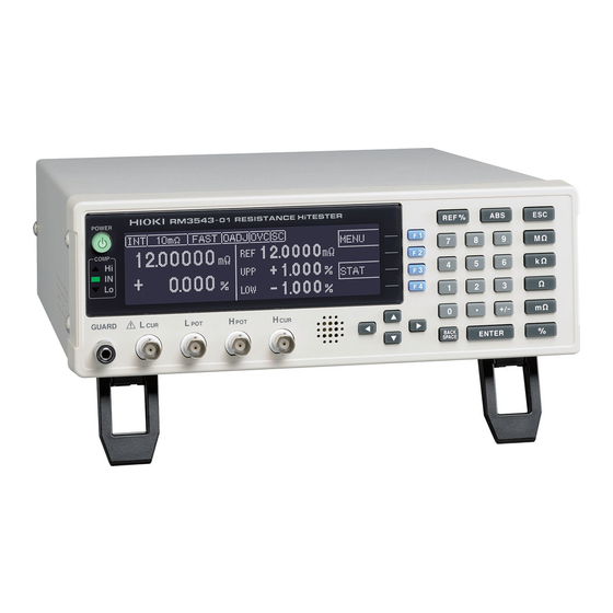
RM3543
RM3543-01
RESISTANCE HiTESTER
Be sure to read this manual before using the instrument.
When using the instrument for the
first time
Names and Functions of
Preparations
Measurement
Sept. 2020 Revised edition 4
RM3543A981-04 20-09H
Parts
p.15
p.21
HIOKI RM3543A981-04
Instruction Manual
Troubleshooting
Maintenance and Service
Remedies
Error Displays and
p.5
p.183
p.185
EN
Advertisement
Table of Contents

Related Manuals for Hioki RM3543


Summary of Contents for Hioki RM3543
- Page 1 RM3543 RM3543-01 Instruction Manual RESISTANCE HiTESTER Be sure to read this manual before using the instrument. p.5 When using the instrument for the Troubleshooting first time Parts p.15 p.183 Names and Functions of Maintenance and Service Preparations Remedies p.21...
- Page 2 HIOKI RM3543A981-04...
-
Page 3: Table Of Contents
(Comparator Function) ....... 34 Enabling and Disabling the Comparator Disabling and Enabling Key Operations Function ............35 ............63 Decide According to Reference Value and Disabling Key Operations Tolerance (REF% Mode) ......35 (Key-Lock Function) ......... 63 RM3543A981-04 HIOKI RM3543A981-04... - Page 4 Store as soon as Measurement is Stable Using the RS-232C Interface ....103 (Auto-Memory Function) ....75 Using the GP-IB Interface (RM3543-01 only) ........104 Performing Statistical Calculations on Configuring the Communications Measured Values .......78 Protocol ..........105 Using Statistical Calculations ....
- Page 5 Appendix 5 Rack Mounting......A 11 Appendix 6 Dimensional Diagram .....A 13 Appendix 7 Calibration.......A 14 Appendix 8 Adjustment Procedure ....A 16 Appendix 9 Table of Commands Compatible with the ADEX AX-1152D ..A 17 Appendix 10Zero Adjustment ....A 19 Index Index 1 HIOKI RM3543A981-04...
- Page 6 Contents HIOKI RM3543A981-04...
-
Page 7: Task-Oriented Reference
To automatically send measure- Export measurement values automatically ment data to a computer (when finished measuring) (p. 81) (RS-232C interface only) Setting Measurement Start Conditions (Trigger Source) (p. 30) Internal trigger (INT) To check operation Calibration (p. A14) HIOKI RM3543A981-04... -
Page 8: Measurement Flow
Data transmission (p. 81) Printing (p. 83) (p. 78) Instrument interface settings must be Computer communications configured before printing or using External control (p. 89) (p. 101) communications or remote control. When Finished Turn the power off (p. 26) HIOKI RM3543A981-04... -
Page 9: Introduction
To obtain maximum performance from the instrument, please read this manual first, and keep it handy for future reference. Model RM3543-01 is the same as the RM3543, but with GP-IB included. Registered trademarks • Microsoft, Windows and Visual Basic are eitherregistered trademarks or trademarks of Microsoft Corporation in the UnitedStates and other countries. - Page 10 Verifying Package Contents Options The following options are available for the instrument. Contact your authorized Hioki distributor or reseller when ordering. The options are subject to change. Visit our website for updated information. Interface Cables Measurement Probes and Fixtures (connect to measurement jacks) ...
-
Page 11: Safety Information
This symbol indicates that the electrical and electronic appliance is put on the EU market after August 13, 2005, and producers of the Member States are required to display it on the appliance under Arti- cle 11.2 of Directive 2002/96/EC (WEEE). HIOKI RM3543A981-04... - Page 12 The value currently being measured and indicated on the measuring instrument. dgt. (resolution) The smallest displayable unit on a digital measuring instrument, i.e., the input value that causes the digital display to show a “1” as the least-significant digit. HIOKI RM3543A981-04...
-
Page 13: Operating Precautions
• Before using the instrument make sure that the insulation on the power cord is undamaged and that no bare conductors are improperly exposed. Using the instrument in such condi- tions could cause an electric shock, so contact your dealer or Hioki representative for repair. - Page 14 • Before using a test fixture, read the instructions provided with it. Before Turning Power On Before turning the instrument on, make sure the supply voltage matches that indi- cated on its power connector. Connection to an improper supply voltage may damage the instrument and present an electrical hazard. HIOKI RM3543A981-04...
- Page 15 • Battery internal resistance cannot be measured with this instrument. It will sustain damage. To measure battery internal resistance, we recommend the HIOKI 3554, 3555, BT3562, BT3563, and 3561 Battery HiTesters.
- Page 16 Operating Precautions HIOKI RM3543A981-04...
-
Page 17: Chapter 1 Overview
Overview 1.1 Product Overview and Features The Hioki RM3543 Resistance HiTester employs the 4-terminal method to quickly and accurately measure the DC resistance of components such as resistors and current sensing resistors. It includes advanced con- tact-check, comparator, and data output functions. The intuitive user interface and high noise immunity are ideal for use with taping machines and separators. - Page 18 Specially designed for current sensing resis- Increase Productivity tors The RM3543 is ideally suited for use in testing current Thanks to its scaling function, the RM3543 can com- sensing resistors, where there has been remarkable pensate for the difference between resistance values progress in lowering resistance values.
- Page 19 Contact checking time can be shortened, improving tact times. Probe Bounce Contact Condition Model Contact Check Measuring RM3543 Previously Reliable Four-Terminal Measurement – Reject Faulty Data – Probe Short-Circuit Detection Function Voltage Level Monitor Function (p. 52) (p. 54)
-
Page 20: Block Diagram
The dual-CPU (C and G) design provides ultra-high-speed measurements and fast system response. • Immunity from electrical noise is provided by isolation between the Measurement and Control blocks (H). • The auto-ranging 100-to-240 V switching power supply (I) can provide stable measurements even in poor power quality environments. HIOKI RM3543A981-04... -
Page 21: Names And Functions Of Parts
• jack: Measurement current Move among the displayed Pass (meets crite- detected terminal setting items. ria) • GUARD jack: Shield (measurement The cursor location is indicat- Measured value is ground) terminal ed by reverse characters. below lower limit HIOKI RM3543A981-04... - Page 22 Compare Two Instruments’ Settings GP-IB Communications SET MONITOR Connector GP-IB Connector (RM3543-01 only) Connect another RM3543 here to compare instru- The GP-IB interface can be used to connect to a computer ment settings (p. 56). (p. 101). Bottom Panel This instrument can be rack mounted.
-
Page 23: Screen Organization
Measurement Screen (p. 18) Return to Previous Screen Basic Settings Screen (p. 18) Return to Previous Screen Detailed Settings Screens (p. 19) Measurement Settings Screens [MEAS SETTINGS] Data Settings Screens [DATA SETTINGS] System Screens [SYSTEM] Indicates a Continued Screen HIOKI RM3543A981-04... - Page 24 Turn comparator on/off (p. 34) Move with cursor keys. LOCK Enable/disable key lock (p. 63) MISC To display the Detailed Settings screen To display the [MEAS SETTINGS] screen To display the [DATA SETTINGS] screen To display the [SYSTEM] screen HIOKI RM3543A981-04...
- Page 25 Data Settings Screen These are settings for memory and statistical calculation functions. (Save, Analysis, and Output) AUTO MEMORY Turn Auto-Memory on/off (p. 75) [DATA SETTINGS] STATISTICS Statistical calculation on/off (p. 78) DATA OUT Automatically output measured values (communications) (p. 81) HIOKI RM3543A981-04...
- Page 26 Key beeper on/off (p. 65) CLOCK (Y-M-D) Set internal clock (p. 68) LINE FREQ Set power source frequency (p. 67) CONTRAST Adjust screen contrast (p. 69) BACKLIGHT Adjust screen backlight (p. 70) RESET Initialize (p. 71) ADJUST Instrument Adjustment (p. A16) HIOKI RM3543A981-04...
- Page 27 (Settings Monitor function) (p. 56) Connect measurement cables (p. 23) Turn the power on (p. 26) Make instrument settings (p. 27) Connect to the test sample When finished measuring, turn the power off (p. 26). HIOKI RM3543A981-04...
-
Page 28: Connecting The Power Cord
• Before using the instrument, make sure that the insulation on the power cord is undamaged and that no bare conductors are improperly exposed. Any damage could cause electric shock, so contact your dealer or Hioki representative. To avoid damaging the power cord, grasp the plug, not the cord, when unplugging it from the power outlet. -
Page 29: Connecting Measurement Cables And Test Fixtures
2.2 Connecting Measurement Cables and Test Fixtures 2.2 Connecting Measurement Cables and Test Fixtures Connect your measurement cables, optional Hioki probes or test fixture to the measurement jacks. Refer to "Options" (p.4) for details. See the instructions provided with the fixture for operating details. -
Page 30: Making Your Own Measurement Cables
Additionally, measurement cables and measurement targets should be kept as far as possible from metal- lic objects. • When using two or more RM3543 units, do not group the wires from multiple instruments together. The "C.E. Volt" error display may be triggered by the phenomenon of induction. - Page 31 • If cutting the ends off of optional measurement cables, make sure that the shield does not touch the center conductor of the H and L cables. Correct measurement is not possible with a shorted cable. • Do not twist wires from multiple units together. HIOKI RM3543A981-04...
-
Page 32: Turning The Power On And Off
When power is turned on again, operation resumes with the same settings as when last turned off. If a power outage (e.g., breaker trip) occurs when the instrument is on, it will automatically turn on again when power is restored (without pressing the POWER button). HIOKI RM3543A981-04... -
Page 33: Chapter 3 Measurement Settings (Basic Measurements)
3.1 Pre-Operation Inspection Before using the instrument for the first time, verify that it operates normally to ensure that no dam- age occurred during storage or shipping. If you find any damage, contact your dealer or Hioki repre- sentative. Peripheral Device Inspection... -
Page 34: Switching 100 M Range Measurement Currents
• During measurement, a transient current equal to about 1.5 times the steady-state current will flow for sev- eral microseconds (or about 10 mApk in the 1 k range). Exercise special care when measuring targets whose characteristics are prone to vary. HIOKI RM3543A981-04... -
Page 35: Setting The Measurement Speed
When performing internal trigger measurement, same as 35 ms when averaging is off. 41 ms 1.6 ms 6.0 ms 34 ms 41 ms 1.6 ms 4.0 ms 34 ms 41 ms 1000 1.6 ms 4.0 ms 34 ms HIOKI RM3543A981-04... -
Page 36: Setting Measurement Start Conditions (Trigger Source)
:INITIATE:CONTINUOUS OFF command via RS-232C or GP- IB. When continuous measurement is disabled, trigger acceptance is controlled only by the host (computer or PLC). See: for trigger command: "Triggering" (p. 142), "9.8 Data Exporting Methods" (p. 152) HIOKI RM3543A981-04... -
Page 37: Selecting The Measurement Range
• During measurement, a transient current equal to about 1.5 times the steady-state current will flow for sev- eral microseconds (or about 10 mApk in the 1 k range). Exercise special care when measuring targets whose characteristics are prone to vary. HIOKI RM3543A981-04... -
Page 38: Zero Adjustment
If no measured value is displayed, increment the measurement range (p. 31). Select whether to enable or disable zero adjustment. Disable zero adjustment (cancel) Selection Execute zero adjustment After confirming that the measured value does not exceed 10 , execute zero adjustment. Return to the Measurement screen. HIOKI RM3543A981-04... - Page 39 • Confirm that the probe connections are correct. When the scaling calculation function is on, you may be unable to zero out the measured value, even if you perform zero adjustment (because the zero-adjusted measured value is still subject to scaling calculation). HIOKI RM3543A981-04...
-
Page 40: Judging Measured Values (Comparator Function)
• If power is turned off during comparator setting, changes to settings are lost as they revert to their previous values. To accept the settings, press the ENTER key. • When setting comparator criteria, the appropriate range is selected automatically. Refer to "Auto-Ranging (when making comparator settings)" (p. 31) for range settings. HIOKI RM3543A981-04... -
Page 41: Enabling And Disabling The Comparator Function
4.5% decision tolerance. ± To abort the setting process, press . Settings are abandoned and the display returns to the previous screen. Open the relative tolerance setting screen. Reference value Positive tolerance (upper decision threshold) Negative tolerance (lower decision threshold) HIOKI RM3543A981-04... - Page 42 (setting) values. • An error message appears if you press ENTER with the positive tolerance set lower than the negative tolerance. See: "11.3 Error Displays and Remedies" (p. 185) (ERR:001) HIOKI RM3543A981-04...
-
Page 43: Decide According To Upper/Lower Thresholds (Abs Mode)
(setting) values. • An error message appears if you press ENTER with the positive tolerance set lower than the negative tolerance. See: "11.3 Error Displays and Remedies" (p. 185) (ERR:001) HIOKI RM3543A981-04... -
Page 44: Confirming Faulty Measurements
C.E. Hi/ C.E. Lo/ C.E. Volt Results Fault COMP indicator: No decision COMP indicator: No decision (FAIL) EXT I/O: ERR signal output EXT I/O: ERR signal output The measurement fault display differs according to detection order and settings. HIOKI RM3543A981-04... - Page 45 1 8 8 80 80 800 Between L and DUT Example of Current Monitor Fault • Broken DUT (open work) • H or L probe contact fault • H or L cable break HIOKI RM3543A981-04...
- Page 46 3.8 Confirming Faulty Measurements HIOKI RM3543A981-04...
-
Page 47: Chapter 4 Customizing Measurement Settings
Set the items as needed. The 100 m range measurement condition settings are configured separately for each measurement current. Consequently, the 100 m range measurement condition settings should be configured after first setting the measurement current (p. 28). HIOKI RM3543A981-04... -
Page 48: Setting Pre-Measurement Delay
Probe Contact Stable Contact Condition Start TRIG Measurement Current Internal Delay* Acquisition of Acquisition Measured Value End of Measurement Signal * Internal delay is provided to suit purely resistive (non-reactive) DUTs, and is different for each measurement range. HIOKI RM3543A981-04... - Page 49 Return to the setting screen. Save setting and return to previous screen. Discard setting and return to previous screen. When using the internal trigger, the delay time (DELAY1) is obtained by adding 100 ms to the setting (to pre- vent heat generation). HIOKI RM3543A981-04...
-
Page 50: Correcting Measured Values (Scaling Function)
Enable the scaling function. Disables the function (default) (go to step 6) Enables the function Selection The setting is specific to the selected range (p. 41) Set the compensation coefficient. Tenkeys Selection Setting range: 0.50000 to 2.00000 (default: 1.00000) HIOKI RM3543A981-04... - Page 51 • Scaling calculation is performed on measured values after zero-adjustment calculation. Consequently, measured values may not equal zero even after zero adjustment. • For the purpose of setting the offset resistance value, range full-scale signifies 1,200,000 dgt. HIOKI RM3543A981-04...
-
Page 52: Setting The Measurement Integration Time Option
(The settings for the current mea- surement range are displayed.) Select the integration setting units. Set in units of time Set in units of power line cycles Selection The setting is specific to the selected range (p. 41) HIOKI RM3543A981-04... - Page 53 • When the effects of power line noise can be ignored, the integration time can be set longer than the default to reduce scattering of measured values. On the other hand, if the integra- tion time is too short, scattering increases. HIOKI RM3543A981-04...
-
Page 54: Stabilizing Measured Values (Averaging Function)
Turning on the averaging function lengthens the external trigger measurement (and command oper- :READ? ation) time to (number of averaging iterations measurement time with averaging turned off). Since a moving average is used for internal trigger measurement, the measurement time does not change. HIOKI RM3543A981-04... -
Page 55: Checking For Poor Or Improper Contact (Contact Check Function)
A contact fault occurs when a measured Selection value exceeds the threshold setting. Return to the Measurement screen. The confirmation screen appears. Return to the setting screen. Save setting and return to previous screen. Discard setting and return to previous screen. HIOKI RM3543A981-04... -
Page 56: Improving Probe Contact (Contact Improver Function)
ON setting Measuring Measurement Internal Contact Improver current: On delay * DELAY 1 DELAY 2 Probe Contact Stable Contact Condition Start TRIG PULSE setting Measurement Measuring Internal Contact Improver current: Pulse DELAY 1 DELAY 2 delay * Approx. HIOKI RM3543A981-04... - Page 57 Set the current limit value. 17mA, 25mA, 35mA (default), 50mA Selection Return to the Measurement screen. The confirmation screen appears. Return to the setting screen. Save setting and return to previous screen. Discard setting and return to previous screen. HIOKI RM3543A981-04...
-
Page 58: Detecting Measurement Voltage Faults (Voltage Level Monitor Function)
Select the voltage level monitor threshold. Loose Normal (default) Selection Severe Return to the Measurement screen. The confirmation screen appears. Return to the setting screen. Save setting and return to previous screen. Discard setting and return to previous screen. HIOKI RM3543A981-04... -
Page 59: Applying Current Only When Measuring (Current Mode Setting)
Contact Improver function is disabled (CONT IMP: OFF, (p. 50)). Return to the Measurement screen. The confirmation screen appears. Return to the setting screen. Save setting and return to previous screen. Discard setting and return to previous screen. HIOKI RM3543A981-04... -
Page 60: Test For Short-Circuited Probe (Probe Short-Circuit Detection Function)
However, short-circuit detection can still be executed by asserting the PRB_CHECK signal. • If probe short-circuit detection coincides with the timing of self-calibration processing, short-circuit detection will not be performed. Short-circuit detection using the PRB_CHECK signal will be performed after self-calibration processing completes. HIOKI RM3543A981-04... - Page 61 Selection Setting range: 1 to 100 ms, 5 ms (default) Return to the Measurement screen. The confirmation screen appears. Return to the setting screen. Save setting and return to previous screen. Discard setting and return to previous screen. HIOKI RM3543A981-04...
-
Page 62: Comparing The Measurement Settings Of Two Instruments (Settings Monitor Function)
Transport Direction Connect the two instruments SET MONITOR connectors together using a Hioki 9637 ’ RS-232C cable. The SET MONITOR connectors are identical to RS-232C connectors. - Page 63 Enter the difference in tolerance (%) to be allowed at the 2nd stage from the tol- erance range set for the 1st stage. Setting range: 0.000 to 9.999% Set the instrument to serve as the 2nd stage (another RM3543). Selects this instrument as the 1st stage Selects this instrument as the 2nd stage Selection Return to the Measurement screen.
- Page 64 1st Stage 2nd Stage TRIG Input Accepted When an error is displayed ERR:003 Comparator settings do not match. Please check. Setting monitor error. (COMP) ERR:004 Measurement speed settings do not match. Please check. Setting monitor error. (SPEED) HIOKI RM3543A981-04...
-
Page 65: Retrying Measurement After A Fault (Retry Function)
Selection Setting range: 1 to 50 ms (default: 50 ms) Return to the Measurement screen. The confirmation screen appears. Return to the setting screen. Save setting and return to previous screen. Discard setting and return to previous screen. HIOKI RM3543A981-04... -
Page 66: Maintaining Measurement Precision (Self-Calibration)
[SYSTEM] Configure self-calibration operation. Configure automatically. (default) Configure manually. Selection Return to the Measurement screen. The confirmation screen appears. Return to the setting screen. Save setting and return to previous screen. Discard setting and return to previous screen. HIOKI RM3543A981-04... -
Page 67: Compensating For Thermal Emf Offset (Offset Voltage Compensation - Ovc)
--------------------- - Offset voltage compensation is automatically enabled for all ranges, and cannot be modified or dis- abled. Depending on the test object, some delay (DELAY2) is required (p. 42) to allow adequate current flow before starting measurement. HIOKI RM3543A981-04... - Page 68 4.14 Compensating for Thermal EMF Offset (Offset Voltage Compensation - OVC) HIOKI RM3543A981-04...
-
Page 69: Chapter 5 System Settings
Enable or disable key operations. Key operations enabled (default) Selection Disable all except key-lock cancel Disable all except key-lock cancel and comparator setting change Return to the Measurement screen. [UNLOCK] is displayed only when key-lock is enabled by front panel key operations. HIOKI RM3543A981-04... -
Page 70: Re-Enabling Key Operations (Key-Lock Cancel)
Re-Enabling Key Operations (Key-Lock Cancel) Key-lock can be canceled only when [UNLOCK] is displayed. Press and hold F1 [UNLOCK] for one second. If key operations are disabled by the KEY_LOCK signal, de-assert (High) the signal to unlock the keys. HIOKI RM3543A981-04... -
Page 71: Setting The Comparator Decision And Key Beepers
Select whether to enable or disable the key beeper. Disables the beeper Enables the beeper (default) Selection Return to the Measurement screen. The confirmation screen appears. Return to the setting screen. Save setting and return to previous screen. Discard setting and return to previous screen. HIOKI RM3543A981-04... -
Page 72: Setting The Comparator Decision ("Judge") Beeper
LOW (beep when below lower threshold) Selection HIGH (beep when above upper threshold) Return to the Measurement screen. The confirmation screen appears. Return to the setting screen. Save setting and return to previous screen. Discard setting and return to previous screen. HIOKI RM3543A981-04... -
Page 73: Power Line Frequency Manual Setting
When the line frequency is 50 Hz When the line frequency is 60 Hz Selection Return to the Measurement screen. The confirmation screen appears. Return to the setting screen. Save setting and return to previous screen. Discard setting and return to previous screen. HIOKI RM3543A981-04... -
Page 74: Setting The Clock
Enter the last two digits of the year, and the month, day, hour, minutes and seconds in that order (the cursor moves automatically). Enter two digits for all values (e.g., 09). Return to the Measurement screen. Clock settings cannot be canceled. HIOKI RM3543A981-04... -
Page 75: Adjusting Screen Contrast
Adjust the contrast. 0 to 100%, 5% step (default: 50%) Selection Return to the Measurement screen. The confirmation screen appears. Return to the setting screen. Save setting and return to previous screen. Discard setting and return to previous screen. HIOKI RM3543A981-04... -
Page 76: Adjusting The Backlight
Adjust the backlight. 0 to 100%, 5% step, (default: 80%) Selection Return to the Measurement screen. The confirmation screen appears. Return to the setting screen. Save setting and return to previous screen. Discard setting and return to previous screen. HIOKI RM3543A981-04... -
Page 77: Initializing (Reset)
The System screen appears. [SYSTEM] Select RESET. Returns all settings to their factory defaults Selection Select whether to cancel or proceed to execute system reset. Cancel the operation Execute The Measurement screen is displayed when system reset finishes. HIOKI RM3543A981-04... -
Page 78: Default Settings
AUTO/ 50 Hz/ 60 Hz AUTO Line frequency (detection) (p. 67) CONTRAST 0 to 100 Screen contrast adjustment (p. 69) BACK LIGHT 0 to 100 Screen backlight adjustment (p. 70) RESET Reset (p. 71) ADJUST Calibration (p. A16) HIOKI RM3543A981-04... -
Page 79: Chapter 6 Storing And Exporting Data
(export) Minimizes transfer time by eliminating the need for transmit re- measurements at the end of quests from the remote controller. (RS-232C interface only) measurement. The data memory and auto-memory functions cannot be enabled at the same time. HIOKI RM3543A981-04... -
Page 80: Storing Data At Specific Times (Data Memory Function)
(p. 31) • upon system reset (p. 71) • when changing comparator settings (p. 34) • when the instrument is turned off • when the scaling setting for the current range is changed (p. 44) HIOKI RM3543A981-04... -
Page 81: Store As Soon As Measurement Is Stable (Auto-Memory Function)
• when the instrument is turned off (p. 77) • • when the scaling setting for the current range is changed when the instrument is turned off (p. 44) HIOKI RM3543A981-04... - Page 82 Disable the function (default) Enable the function Selection Return to the Measurement screen. The confirmation screen appears. Return to the setting screen. Save setting and return to previous screen. Discard setting and return to previous screen. When the function is enabled HIOKI RM3543A981-04...
- Page 83 When the measurement is stable, the value is automatically stored and the count is incremented. When the count reaches the specified number of values, a long beep sounds, and subsequent mea- surements are not stored. The (one) last acquired value can be deleted (Undo function (p. 80)). HIOKI RM3543A981-04...
-
Page 84: Performing Statistical Calculations On Measured Values
(p. 34) • upon setting the auto-memory number of values to store • when the scaling setting for the current range is changed (p. 77) (p. 44) • when the instrument is turned off HIOKI RM3543A981-04... - Page 85 The confirmation screen appears. Return to the setting screen. Save setting and return to previous screen. Discard setting and return to previous screen. When statistical calculation is enabled, F3 [STAT] appears on the Measurement screen. Confirm calculation results (p. 80) HIOKI RM3543A981-04...
-
Page 86: Using Statistical Calculations
Statistical calculation results and stored data are erased when printing finishes. To erase Erases the last measurement and calcula- tion result (executes only once). Erases all measured values and statistical calculation results. After selecting, a confirmation screen ap- pears. HIOKI RM3543A981-04... -
Page 87: Auto-Exporting Measured Values (At End Of Measurement) (Data Output Function)
Enable or disable auto-exporting (DATA OUT) Disable auto-exporting (default) Enable auto-exporting Selection Return to the Measurement screen. The confirmation screen appears. Return to the setting screen. Save setting and return to previous screen. Discard setting and return to previous screen. HIOKI RM3543A981-04... - Page 88 6.4 Auto-Exporting Measured Values (at End of Measurement) (Data Output Function) HIOKI RM3543A981-04...
-
Page 89: Chapter 7 Printing
• Characters per line ....At least 45 • Communication speed... 9600 bps • Data bits ........ 8 • Parity ........none • Stop bits ........ 1 • Flow control ......none • Control codes ......Capable of directly printing plain text HIOKI RM3543A981-04... -
Page 90: Connecting The Printer To The Instrument
Turn the instrument and printer on. AC adapter RS-232C cable Connector Pinouts 1 2 3 4 5 13 ....... 1 25 ....... 14 6 7 8 9 RM3543 (9-pin) Connector Printer (25-pin) Connector (Example) Signal Signal Function Function Name Name... -
Page 91: Instrument Settings
Select PRINT as the interface type. To use the printer Selection Return to the Measurement screen. The confirmation screen appears. Return to the setting screen. Save setting and return to previous screen. Discard setting and return to previous screen. HIOKI RM3543A981-04... -
Page 92: Printing
"6.3 Performing Statistical Calculations on Measured Values" (p. 78) (When statistical calculation is enabled) If no valid data exists, only the data count is printed. When only one valid data sample exists, standard devia- tion of sample and process capability indices cannot be printed. HIOKI RM3543A981-04... - Page 93 The “Valid” statistical calculation result indicates the number (count) of data samples not subject to errors such as measurement faults. • Among the comparator decision result counts (Hi, IN, Lo, and OR), “OR” indicates the number (count) of out-of-range measurements. HIOKI RM3543A981-04...
- Page 94 7.3 Printing HIOKI RM3543A981-04...
-
Page 95: Chapter 8 External Control
• Be careful not to short-circuit ISO_5V to ISO_COM. • Be careful not to short-circuit ISO_12V to ISO_COM. • Do not draw loads from ISO_5V and ISO_12V at the same time. See: "Connector Type and Signal Pinouts" (p. 90) HIOKI RM3543A981-04... -
Page 96: Connector Type And Signal Pinouts
• The 0ADJ signal should be asserted (Low) for at least 10 ms. • The connector shell is conductively connected to the metal instrument chassis and the protective earth pin of the power plug. Be aware that it is not isolated from ground. HIOKI RM3543A981-04... -
Page 97: Signal Descriptions
• Input signals are ignored when the following are displayed: Basic, Detailed, and Comparator Settings screens; Statistical Calculation Results screen (except for the print signal); and error messages (except Setting Monitor errors). • EXT I/O input and output signals are not usable while changing measurement settings. HIOKI RM3543A981-04... -
Page 98: Timing Chart
TRIG End of Measurement See: "Setting End-of-Measurement Signal Output (EOM Signal Setting)" (p. 97) The EOM signal is de-asserted when the next measurement is started by the next TRIG signal. HIOKI RM3543A981-04... - Page 99 1 to 100 ms Setting-dependent *1: When the averaging function is on, the processing (t3 + t4) (time) is repeated the set number of times. Internal Delay Range Internal Delay [ms] 10m 100m (1A) 100m (100mA) 1000m 10 100 1000 HIOKI RM3543A981-04...
-
Page 100: Internal Circuitry
Internally Isolated 5 V Output Common Internally Isolated Do not apply external power Common Signal Ground Output Circuit PLC, etc. (Controller) Internally Isolated 12 V Internally Isolated 5 V Input Zener Voltage 30 V Common Internally Isolated Common Signal Ground HIOKI RM3543A981-04... -
Page 101: Electrical Specifications
Maximum output current 20 mA External power input none • The maximum output current figures for the +5 V and +12 V power outputs assume standalone use. Do not draw loads from the power supplies at the same time. HIOKI RM3543A981-04... -
Page 102: Connection Examples
PLC Output (Source Output) Connections Output Circuit Connection Examples Output Output LED Connection Relay Connections Output Output Output Active-Low Logic Output Active-Low Logic Output Wired OR Common Output Input Output Input Common PLC Input (Source Input) Connections PLC Input (Sink Input) Connections HIOKI RM3543A981-04... -
Page 103: External I/O Settings
Setting range: 1 ms to 100 ms (default: 5 ms) Return to the Measurement screen. The confirmation screen appears. Return to the setting screen. Save setting and return to previous screen. Discard setting and return to previous screen. HIOKI RM3543A981-04... -
Page 104: Setting The Trigger (Trig) Signal Logic
Measurement starts at the falling (ON) edge of the (active-low) signal. (default) Selection Return to the Measurement screen. The confirmation screen appears. Return to the setting screen. Save setting and return to previous screen. Discard setting and return to previous screen. HIOKI RM3543A981-04... -
Page 105: External Control Q&A
PLC side. Can free-running measured values be Please use the free software for acquiring measured values available for download from our website. acquired using a footswitch? HIOKI RM3543A981-04... -
Page 106: Supplied Connector Assembly
5. In one half of cover (A), place connector (H), clamps (F), saddle washers (G) and screws (D). 6. Place the other half of cover (A) on top. 7. Affix the halves of the cover (A) together with screws (B) and nuts (E). Be careful not to overtighten the screws, which could damage the covers. HIOKI RM3543A981-04... -
Page 107: Chapter 9 Communications
*1. ANSI/IEEE Standard 488.1-1987, IEEE Standard Digital Interface for Programmable Instrumentation *2. ANSI/IEEE Standard 488.2-1987, IEEE Standard Codes, Formats, Protocols, and Common Commands *3. The situation in which the input buffer and the output queue become full, so that processing cannot continue. HIOKI RM3543A981-04... -
Page 108: Specifications
The I/O connector is a DTE (Data Terminal Equipment) configuration Recommended cables: Model 9637 RS-232C Cable (for PC) Model 9638 RS-232C Cable (for D-sub25pin connector) Operating Code: ASCII codes GP-IB Specifications (Interface Functions) (RM3543-01 only) All Source Handshake functions All Acceptor Handshake functions ... -
Page 109: Connecting
Data Terminal Ready Active (ON) level is +5 to +9 V (constant) Signal Ground Data Set Ready Not used Request to Send Active (ON) level is +5 to +9 V (constant) Clear to Send Not used Ring Indicator Not used HIOKI RM3543A981-04... -
Page 110: Using The Rs-232C Interface
PC/AT-end Pin No. Pin No. Recommended cable: HIOKI Model 9637 RS-232C Cable (1.8 m) Connecting a controller with a 25-pin D-sub female port Use a crossover cable with a female 9-pin D-sub and a male 25-pin D-sub connector. As the figure shows, RTS and CTS pins are shorted together and crossed to DCD in the other connector. -
Page 111: Configuring The Communications Protocol
Be sure to make set up the controller as shown below. • • Asynchronous communication Stop bit: 1 • • Transfer rate: 9600bps/ 19200bps/ 38400bps Data length: 8 • (set to match the instrument setting) Parity check: None HIOKI RM3543A981-04... -
Page 112: Configuring Gp-Ib Interface Communications (Rm3543-01 Only)
Return to the Measurement screen. The confirmation screen appears. Return to the setting screen. Save setting and return to previous screen. Discard setting and return to previous screen. “GP-IB” is only displayed on model RM3543-01 (equipped with GP-IB). HIOKI RM3543A981-04... -
Page 113: Select The Measurement Data Transmission Format (Both Rs-232C And Gp-Ib)
Responses containing multiple values such as memory data consist of a continuous stream of binary data val- ues with no punctuation or other separator between values. Example :MEMory:DATA? Transmit + (terminator) Receive (4-byte floating-point data) + (4-byte floating-point data) +..+ (4-byte floating-point data) HIOKI RM3543A981-04... -
Page 114: Communication Methods
Messages can be either program messages, sent from the controller such as PC to the instrument, or response messages, sent from the instrument to the controller. Program Messages Message types are further categorized as follows Command Message Controller RM3543 Program Messages Query Message Messages Response Messages Response Message When issuing commands that contain data, make certain that the data is provided in the specified format. -
Page 115: Message Format
FUNCTION OK (long form) FUNC OK (short form) FUNCT Error Error Response messages generated by the instrument are in long form and in upper case letters. HIOKI RM3543A981-04... - Page 116 • • LF with EOI From the instrument's interface settings, the following can be selected as the terminator for response messages. • • LF with EOI (initial setting) CR+LF • CR+LR with EOI See: "Delimiter Setting" (p. 139) HIOKI RM3543A981-04...
- Page 117 The instrument does not fully support IEEE 488.2. As much as possible, please use the data formats shown in the Reference section. Also, be careful to avoid constructing single commands that could overflow the input buffer or output queue. HIOKI RM3543A981-04...
-
Page 118: Output Queue And Input Buffer
If 256 bytes are allowed to accumulate in this buffer so that it becomes full, the GP-IB inter- face bus enters the waiting state until space is cleared in the buffer. The RS-232C interface will not accept data beyond 256 bytes. Ensure that the no command ever exceeds 256 bytes. HIOKI RM3543A981-04... -
Page 119: Status Byte Register
SRQ (Service Request) is a GP-IB function only. However, STB (Status Byte Register) infor- mation can be acquired with RS-232C using the STB? command. RS-232C does not provide a function for issuing service requests. Still, SRER setup and STB reading are available. HIOKI RM3543A981-04... - Page 120 This is the logical sum of Event Status Register 0. Service Request Enable Register (SRER) This register masks the Status Byte Register. Setting a bit of this register to 1 enables the cor- responding bit of the Status Byte Register to be used. HIOKI RM3543A981-04...
-
Page 121: Event Registers
When the next command is received while there is data in the output queue Request Control Bit 1 (unused) Operation Complete This bit is set to 1 in response to an command. Bit 0 • It indicates the completion of operations of all messages up to the command HIOKI RM3543A981-04... - Page 122 Event Status Registers 0 and 1 are cleared in the following situations: CLS • When a command is executed :ESR0? :ESR1? • When an Event Status Register query ( ) is executed • When the instrument is powered on HIOKI RM3543A981-04...
- Page 123 & & & & & & bit 7 bit 6 bit 5 bit 4 bit 3 bit 2 bit 1 bit 0 VOLT CURR CE Hi CE Lo Event Status Enable Register 1 (ESER1) HIOKI RM3543A981-04...
-
Page 124: Initialization Items
LF+EOI LF+EOI LF+EOI (GP-IB) Response message separator *1. Only the MAV bit (bit 4) is cleared. *2. All bits except the MAV bit are cleared. *3. Except the PON bit (bit 7). HIOKI RM3543A981-04... -
Page 125: Command Execution Time
When message syntax (spelling) is invalid. When the data format in a command or query is invalid. • Query Error When the response message exceeds 64 bytes • Execution Error When invalid character or numeric data is present HIOKI RM3543A981-04... -
Page 126: Message List
Queries the Status Byte Register. TRG Executes one sampling. TST? [0 to 7] Initiates a self-test and queries the result. WAI Wait for operations to finish. Notes: • < >: contents of the data portion. • [ ]: Response data HIOKI RM3543A981-04... -
Page 127: Device-Specific Commands
:CALCulate:STATistics:LIMit? Queries comparator results. fault count>,<Out-of-range count>] :CALCulate:STATistics:DEViation? Queries standard deviation. [< n>,< n-1>] Queries the process capability indi- :CALCulate:STATistics:CP? [<Cp>,<CpK>] ces. Notes: • < >: contents of the data portion. • [ ]: Response data HIOKI RM3543A981-04... - Page 128 Sets and queries the EOM output mode. :SYSTem:EOM:MODE? [HOLD/ PULSE] :SYSTem:EOM:PULSe 0.001 to 0.100 Sets and queries the EOM pulse width. 138 :SYSTem:EOM:PULSe? [0.001 to 0.100] Notes: • < >: contents of the data portion. • [ ]: Response data HIOKI RM3543A981-04...
- Page 129 Sets and queries Trigger Delay 1 time. 144 :TRIGger:DELay1? [0 to 0.100] :TRIGger:EDGE RISE/ FALL Sets and queries trigger (falling (ON)/ rising (OFF)) edge logic. :TRIGger:EDGE? Notes: • < >: contents of the data portion. • [ ]: Response data HIOKI RM3543A981-04...
- Page 130 [ON/ OFF] :RESistance:VMONitor:LEVel <Range>,<Level> Sets and queries voltage level monitor <Range> level. :RESistance:VMONitor:LEVel? [L1/ L2/ L3] Notes: • < >: contents of the data portion. • [ ]: Response data • <Range>: RNG10MIL/ RNG100MIL/ RNG1000MIL/ RNG10/ RNG100/ RNG1000 HIOKI RM3543A981-04...
- Page 131 Sets and queries the scaling function's [-10% of range measure- offset. :RESistance:SCALing:PARameterB? ment range to 10% of range measurement range] Notes: • < >: contents of the data portion. • [ ]: Response data • <Range>: RNG10MIL/ RNG100MIL/ RNG1000MIL/ RNG10/ RNG100/ RNG1000 HIOKI RM3543A981-04...
-
Page 132: Message Reference
2 bit 1 bit 0 Shows an example of an actual Example ESE 36 command application. (Sets bits 5 and 2 of SESER) (Normally described with HEADER (except the HEADER command itself)). Command, Query Measurement Instrument Response HIOKI RM3543A981-04... - Page 133 IDN? <Manufacturer's name>,<Model name>,0,<Software version> Response Example HIOKI,RM3543,0,V1.00 The Device ID is HIOKI RM3543, 0, software version 1.00. For model RM3543-01, the <Model name> is RM3543-01. Note The response message has no header. (2) Internal Operation Command Initialize Device...
- Page 134 Note command is supported because it is defined in IEEE 488.2-1987, but because all Model RM3543 device-specific commands are sequential types, this command has no actual affect. (4) Status and Event Control Commands Clear the Status Byte and Related Queues (Except the Output Queue)
- Page 135 3 bit 2 bit 1 bit 0 unused unused unused bit 7 bit 6 bit 5 bit 4 bit 3 bit 2 bit 1 bit 0 Example ESR? Bit 5 of the SESR was set to 1. HIOKI RM3543A981-04...
- Page 136 When Statistical Calculation is ON, imports calculation data. When the memory function is enabled, the measured value is stored. Example :TRIGger:SOURce EXTernal; Note When an error occurs with the Settings Monitor function enabled, triggering is disabled (p. 56). HIOKI RM3543A981-04...
-
Page 137: Device-Specific Commands
VOLT CURR CE Hi CE Lo Note Data initializes to zero at power-on. Read Device-Specific Event Status Registers ESR1 Syntax Query :ESR1? Response <0 to 255 (NR1)> Note Executing ESR1? clears the contents of ESR1. HIOKI RM3543A981-04... - Page 138 Enter the expected measurement value. The instrument is set to the most suitable range for measuring the given numerical value data. Query Queries the measurement range setting. Example RES:RANG 95 Sets the Resistance measurement to the 100 range. HIOKI RM3543A981-04...
- Page 139 = Indicates zero-adjustment succeeded. = Indicates the offset resistance exceeded 10 during zero-adjustment. (3) Sampling Set and Query Measurement Speed Syntax Command :SPEEd <FAST/ MEDium/ SLOW> Query :SPEEd? Response <FAST/ MEDIUM/ SLOW> Example :SPEE MED :SPEE? MEDIUM HIOKI RM3543A981-04...
- Page 140 Response <Mean (NR3)> Query the Maximum value Syntax Query :CALCulate:STATistics:MAXimum? Response <Maximum value (NR3)>,<Data No. of Maximum value (NR1)> Example :CALC:STAT:MAX? 12.4859E+0,1124 Query the Minimum value Syntax Query :CALCulate:STATistics:MINimum? Response <Minimum value (NR3)>,<Data No. of Minimum value (NR1)> HIOKI RM3543A981-04...
- Page 141 Comparator State Syntax Command :CALCulate:LIMit:STATe <1/ 0/ ON/ OFF> Query :CALCulate:LIMit:STATe? Response <ON/ OFF> Example :CALC:LIM:STAT ON Beeper State Syntax Command :CALCulate:LIMit:BEEPer <OFF/ HI/ LO/ HL/ IN> Query :CALCulate:LIMit:BEEPer? Response <OFF/ HI/ LO/ HL/ IN> Example :CALC:LIM:BEEP HL HIOKI RM3543A981-04...
- Page 142 = -99.990 to 99.990 (NR2) <Lower threshold (%)> = -99.990 to 99.990 (NR2) ± Note Setting resolution is 0.01% for 10.00% or more. Example :CALC:LIM:PERC 1.505,-2.005 Queries the comparator result Syntax Query :CALCulate:LIMit:RESult? Response <HI/ IN/ LO/ OFF/ ERR> Example :CALC:LIM:RES? HIOKI RM3543A981-04...
- Page 143 Consequently, the 100 m range measurement condition settings should be configured after first setting the measurement current. Set and Query the Key Beeper Setting Syntax Command :SYSTem:BEEPer:STATe <1/ 0/ ON/ OFF> Query :SYSTem:BEEPer:STATe? Response <ON/ OFF> Example :SYST:BEEP:STAT ON :SYST:BEEP:STAT? HIOKI RM3543A981-04...
- Page 144 = Sets EOM=OFF according to the specified pulse width. Example :SYST:EOM:MODE PULS EOM Pulse Width Setting Syntax Command :SYSTem:EOM:PULSe <Pulse width> Query :SYSTem:EOM:PULSe? Response Pulse width < > <Pulse width> = 0.001 to 0.100 (NR2) (seconds) Example :SYST:EOM:PULS 0.005 HIOKI RM3543A981-04...
- Page 145 :SYSTem:BACKup Description Stores current measurement settings in non-volatile memory. Changes to measurement settings by communications commands are not backed up (and are lost when power is turned off). Use this command to store the settings as occasion demands. HIOKI RM3543A981-04...
- Page 146 ON: The measured value is automatically sent each time an externally triggered measurement is finished. During internal triggering, measured values are sent automatically whenever the TRIG signal is applied. OFF: Measured values are not automatically sent. This command is not applicable to the GP-IB Interface. HIOKI RM3543A981-04...
- Page 147 <0.001 to 0.05 (seconds)> Query :SYSTem:RETRy:TIME? Response <0.001 to 0.05 (NR1)> (seconds) Example :SYST:RETR:TIME 0.02 System Reset Syntax Command :SYSTem:RESet Description Initializes all except communications and clock settings. After initialization, settings are stored in non-volatile memory for backup. HIOKI RM3543A981-04...
- Page 148 If this has been set to OFF when operation is returned to the Local state or power is turned off, the following state occurs when power is turned back on. :INITIATE:CONTINUOUS ON ("To cancel the Remote state (enter the local state)" (p. 108) Exporting measured values: "9.8 Data Exporting Methods" (p. 152) HIOKI RM3543A981-04...
- Page 149 <EXTERNAL> = External triggering Trigger by pressing F4 [MANU] on the [MENU]-[TRG] selection screen, TRIG signal or Description command. Example :TRIG:SOUR IMM :TRIG:SOUR? IMMEDIATE Note When external (EXT) triggering is enabled, the auto-memory mode is disabled (OFF). HIOKI RM3543A981-04...
- Page 150 ±100.0000E+7 +100.0000E+8 1000m ± ±1000.000E+6 +1000.000E+7 10 ± ±10.00000E+8 +10.00000E+9 100 ± ±100.0000E+7 +100.0000E+8 1000 ± ±1000.000E+6 +1000.000E+7 Note For positive measured values, a space (ASCII 20H) represents the sign. HIOKI RM3543A981-04...
- Page 151 Memory function) enabled, returned measured values will be duplicated. Therefore, disable the Auto-Memory function when triggering externally. See: "6.4 Auto-Exporting Measured Values (at End of Measurement) (Data Output Function)" (p. • Binary data is returned when the Binary sending format is selected. HIOKI RM3543A981-04...
- Page 152 Enabling the auto-memory mode automatically selects internal [INT] triggering and enables sta- tistical calculation. Clear Memory Data Syntax Command :MEMory:CLEar Example :MEM:CLE Retrieve the Memory Data Count Syntax Query :MEMory:COUNt? Response <Memory data count > <Memory data count > = 0 to 30000 (NR1) Example :MEM:COUN? HIOKI RM3543A981-04...
- Page 153 When the auto-memory mode is enabled, the maximum memory point number is 99. Although the value may be set higher with the :MEMory:POINt command, the memory is limited to 100 measurement values. • When the auto-memory mode is enabled, stored data is erased when the memory point number is changed. HIOKI RM3543A981-04...
- Page 154 <Integration time (seconds)> Query :RESistance:APERture? <Range> <Speed> Response <Integration time (seconds)> <Range> = RNG10MIL/ RNG100MIL/ RNG1000MIL/ RNG10/ RNG100/ RNG1000 <Speed> = SLOW/ MEDium/ FAST <Integration time> = 0.0001 to 0.1 (seconds) Description Sets the integration time, in seconds. HIOKI RM3543A981-04...
- Page 155 When using the Contact Improver function (set to HOLD or PULSE), measurement current is only applied as a pulse, even if CONTinuous is selected here. Therefore, to measure with continuous current, the Contact Improver function must be disabled (set to OFF). (p. 149) HIOKI RM3543A981-04...
- Page 156 Command :RESistance:VMONitor:LEVel <Range> <Level> Query :RESistance:VMONitor:LEVel? <Range> Response <Level> <Range> = RNG10MIL/ RNG100MIL/ RNG1000MIL/ RNG10/ RNG100/ RNG1000 <Level> L1/ L2/ L3 (L1: Loose/ L2: Normal/ L3: Severe) Description Sets the error level for the voltage level monitor function. HIOKI RM3543A981-04...
- Page 157 Set and Query Scaling Function's Offset Syntax Command :RESistance:SCALing:PARameterB <Range> <Offset> Query :RESistance:SCALing:PARameterB? <Range> Response <Offset> <Range> = RNG10MIL/ RNG100MIL/ RNG1000MIL/ RNG10/ RNG100/ RNG1000 <Offset> = -10% of range measurement range to 10% of range measurement range Description Sets the scaling function's offset. HIOKI RM3543A981-04...
-
Page 158: Data Exporting Methods
(external triggering) Exporting :READ? When triggered by the [MANU] Key or TRIG signal, a measurement is taken and the result is transferred. *1. The [MANU] key indicator is displayed when [TRG: EXT] is selected on the Basic Setting screen. HIOKI RM3543A981-04... - Page 159 Start Single Measurement Command Processing Returns the measured value after Response single measurement to the PC Use this method to measure (and export) synchronously with the PC or external trigger signal. Measurement time can be minimized. HIOKI RM3543A981-04...
-
Page 160: Sample Programs
While Right(recvstr, 1) <> Chr(10) recvstr = recvstr + MSComm1.Input DoEvents Wend recvstr = Left(recvstr, Len(recvstr) - 2) 'Delete the terminator (CR+LF) Print #1, Str(i) & "," & recvstr 'Write to the file Next Close #1 MSComm1.PortOpen = False End Sub HIOKI RM3543A981-04... - Page 161 While Right(recvstr, 1) <> Chr(10) recvstr = recvstr + MSComm1.Input DoEvents Wend recvstr = Left(recvstr, Len(recvstr) - 2) 'Delete the terminator (CR+LF) Print #1, Str(i) & "," & recvstr 'Write to the file Next Close #1 MSComm1.PortOpen = False End Sub HIOKI RM3543A981-04...
- Page 162 9.9 Sample Programs External Trigger Measurement 1 Measure and import according to external triggering of the RM3543 [MANU] key or TRIG signal input), and save measurements in a text file. Private Sub MeasureTrigSubRS() Dim recvstr As String 'Receiving char string Dim i As Integer MSComm1.Settings = "9600,n,8,1"...
- Page 163 Measure and import according to external triggering of the RM3543 [MANU] key or TRIG signal input), and save measurements in a text file. (The RM3543 imports the most recent measurement by trigger input timing with the continuous measurement state) Private Sub MeasureTrig2SubRS()
- Page 164 MSComm1.Output = ":CALC:LIM:MODE REF" & vbCrLf 'From here on, comparator settings MSComm1.Output = ":CALC:LIM:BEEP HL" & vbCrLf MSComm1.Output = ":CALC:LIM:REF 1E+0" & vbCrLf MSComm1.Output = ":CALC:LIM:PERC 1.0, -1.5" & vbCrLf MSComm1.Output = ":CALC:LIM:STAT ON" & vbCrLf 'Comparator ON MSComm1.PortOpen = False End Sub HIOKI RM3543A981-04...
- Page 165 Dim ud As Integer 'State (unused) Dim i As Integer pad = 0 'Board Address 0 gpibad = 1 'RM3543 Address 1 timeout = T10s 'Timeout about 10s Call ibfind("gpib0", 0) 'Initialize GP-IB Call ibdev(pad, gpibad, 0, timeout, 1, 0, ud) Call SendIFC(pad) Open App.Path &...
- Page 166 'Send ":READ?" to measure and import the mea- surement Call Receive(pad, gpibad, buffer, STOPend) 'Receive recvstr = Left(buffer, InStr(1, buffer, Chr(10)) - 1) Print #1, Str(i) & "," & recvstr 'Write to the file Next Close #1 Call ibonl(pad, 0) End Sub HIOKI RM3543A981-04...
- Page 167 9.9 Sample Programs External Trigger Measurement 1 Measure and import according to external triggering of the RM3543 [MANU] key or TRIG signal input), and save measurements in a text file. Private Sub MeasureTrigSub() Dim buffer As String 20 'Receiving buffer...
- Page 168 Measure and import according to external triggering of the RM3543 [MANU] key or TRIG signal input), and save measurements in a text file. (The RM3543 imports the most recent measurement by trigger input timing with the continuous measurement state) Private Sub MeasureTrig2Sub() Dim buffer As String 20...
- Page 169 'Timeout period Dim ud As Integer 'State (unused) pad = 0 'Board Address 0 gpibad = 1 'RM3543 Address 1 timeout = T10s 'Timeout about 10s Call ibfind("gpib0", 0) 'Initialize GP-IB Call ibdev(pad, gpibad, 0, timeout, 1, 0, ud) Call SendIFC(pad) Call Send(pad, gpibad, ":FUNC RES", NLend)
- Page 170 This section describes an example of how to use the Windows development language Visual ® Basic 2005 Express Edition to operate the RM3543 unit from a PC via RS-232C, incorporate mea- surement values, and save measurement values to a file. ® Visual Basic...
- Page 171 View Code Right Click Click ® Visual Basic Follow the procedure below so that the 2005 window becomes as shown in the diagram below. Write a program referring to Sample program (p. 166), and execute the created program. HIOKI RM3543A981-04...
-
Page 172: Sample Programs (Visual Basic 2005)
Button created to close application Button2 When the [ Begin Measurement ] is pressed, the RM3543 takes 10 measurements and writes the measurement values to a [ data.csv ] file. When the [ Quit ] button is pressed the program closes. - Page 173 (e) Opens the “data.csv” file. However, if a file with this name already exists, the previous “data.csv” will be deleted and a new file created. (f) Sends the command to the RM3543 to perform one measurement and return that measurement result to the computer.
-
Page 174: Device Compliance Statement
“Information on compliance to standards” based on the IEEE 488.2 standard 1. IEEE 488.1 interface functions See: "GP-IB Specifications (Interface Functions) (RM3543-01 only)" (p. 102) 2. Operation with a device address other than 0 A setting outside the 0 to 30 range cannot be made. - Page 175 23.Criterion relating to the functions required at Termination occurs when the command has been parsed. :READ? the instant that the termination message is query finishes when the measurement data is produced, as a response to each command received. HIOKI RM3543A981-04...
- Page 176 9.10 Device Compliance Statement HIOKI RM3543A981-04...
-
Page 177: Chapter 10 Specifications
-9.999% to +9.999% (when |Upper limit value| and |Lower limit value| are 10% or less) -99.99% to +99.99% (when |Upper limit value| or |Lower limit value| is more than 10%) ABS Mode Upper/Lower limit ranges 0.0000 m to 1200.00 HIOKI RM3543A981-04... - Page 178 Adjusts measurement object response (for each range) Default state 0.0 ms Setting range 0.0 ms to 100.0 ms (5) OVC (Offset Voltage Compensation) Operation Reverses measurement current polarity to eliminate offset voltage effects Applicable ranges 10 m to 1000 range (All ranges) HIOKI RM3543A981-04...
- Page 179 Threshold setting / 100 / 150 / 200 / 300 / 400 / 500 (reference value) Current Monitor Function Operation Detects faults that can obstruct normal measurement current. This function cannot be disabled. HIOKI RM3543A981-04...
- Page 180 17 mA, 25 mA, 35 mA, 50 mA (peak current reference value) (11) Current Mode Setting Operation Enable if measurement current flows when not measuring. (for each range) The CONT (continuous) setting is available only when the Contact Improver function is disabled. Default state PULSE Setting CONT/ PULSE HIOKI RM3543A981-04...
- Page 181 (17) Output Data Format Setting Default state ASCII Setting ASCII/ BINARY (18) Comparator Beeper Setting Default state OFF, HIGH, or LOW Audibility ON/ OFF Signaling criteria HIGH/ LOW/ HIGH or LOW/ IN (19) Key-Press Beeper Setting Default state Setting ON/ OFF HIOKI RM3543A981-04...
- Page 182 Memory is cleared when acquired data has been transferred or printed by RS-232C During Auto-Memory operation, the statistical calculation function is always enabled. The voltage level monitor function is disabled. Default state OFF/ 10 Setting ON/ OFF Number of measurements stored: 1 to 99 HIOKI RM3543A981-04...
- Page 183 (32) Key-Lock Functions Operation Disables operation of unneeded keys. Setting (1) Disables all except the comparator setting and cancel keys (2) Disables all except the cancel key (3) All front panel keys are disabled when the KEY_LOCK signal is received. HIOKI RM3543A981-04...
- Page 184 However, loads cannot be drawn from the +5 V and +12 V power supplies at the same time. (2) Isolation: Floating from protective ground potential and measurement circuit Insulation rating vs. ground: not more than 50 VDC, 30 V rms AC, and 42.4 V pk AC HIOKI RM3543A981-04...
- Page 185 Parity none Delimiter Transmit CR+LF, Receive CR or CR+LF Handshake No X-flow, no hardware flow GP-IB interface (RM3543-01 only) Communication contents Remote control Interface Functions All Source Handshake functions are supported. All Acceptor Handshake functions are supported. Basic talker functions are supported.
- Page 186 (reading or displayed value) The value currently being measured and indicated on the measuring instrument. • dgt. (resolution) The smallest displayable unit on a digital measuring instrument, i.e., the input value that causes the digital display to show a “1” as the least-significant digit. HIOKI RM3543A981-04...
- Page 187 Approx. 260W x 88H x 300D mm (10.24"W × 3.46"H × 11.81"D) Mass Approx. 3.0 kg (105.8 oz.) Product warranty 3 years Accessories • Power Cord (2-line + ground) (1) • EXT I/O Male Connector (1) • Instruction Manual (This document) (1) • Operation Guide (1) HIOKI RM3543A981-04...
- Page 188 Model 9263 SMD Test Fixture (less than 10 m residual resistance after zero adjustment) Interface Cables: • Model 9637 RS-232C Cable (9-pin to 9-pin/ crossover cable) • Model 9638 RS-232C Cable (9-pin to 25-pin/ crossover cable) • Model 9151-02 GP-IB Connector Cable (2 m) HIOKI RM3543A981-04...
-
Page 189: Chapter 11 Maintenance And Service
We do not take any responsibility for damage incurred during shipping. Replaceable Parts and Operating Lifetimes Useful life depends on the operating environment and frequency of use. Operation cannot be guaranteed beyond the following periods. For replacement parts, contact your dealer or Hioki representative. Part Life LCD (to half brightness) Approx. - Page 190 • To clean the instrument, wipe it gently with a soft cloth moistened with water or mild deter- gent. Never use solvents such as benzene, alcohol, acetone, ether, ketones, thinners or gasoline, as they can deform and discolor the case. • Wipe the LCD gently with a soft, dry cloth. HIOKI RM3543A981-04...
-
Page 191: Error Displays And Remedies
11.3 Error Displays and Remedies 11.3 Error Displays and Remedies The following messages are displayed when the instrument detects an error or abnormal measurement set- ting. If repair is necessary, contact your dealer or Hioki representative. Display Description Remedy +OvrRng/-OvrRng Measurement out of range (p. - Page 192 Confirm system reset. INFO:024 System Reset? (F1:CANCEL/ F4:YES) Waiting for key code entry to ac- INFO:031 Press enter code. cess adjustment mode. Not measuring When awaiting a trigger after changing settings, and immedi- ately after power-on. HIOKI RM3543A981-04...
-
Page 193: Disposing Of The Instrument
Take care not to short the + and -. Doing so may cause sparks. Battery Holder CALIFORNIA, USA ONLY This product contains a CR Coin Lithium Battery which contains Perchlorate Material - special handling may apply. See www.dtsc.ca.gov/hazardouswaste/perchlorate HIOKI RM3543A981-04... - Page 194 11.4 Disposing of the Instrument HIOKI RM3543A981-04...
-
Page 195: Appendix
E across the measurement terminals and voltage E across test object resistance R are essentially equal, allowing test object resistance to be measured without being affected by r to r HIOKI RM3543A981-04... -
Page 196: Appendix 2 Effect Of Thermal Emf
Because this instrument functions by measuring potential difference while applying a constant direct RM3543 current through the test object, the effect of thermal emf can affect measurements. The amplitude of ther- mal emf depends on the temperature of the measure- ment environment, with the force generally being greater at higher temperature. -
Page 197: Appendix 3 Unstable Measurement Values.a
Figs. 2 and 3. If thermal emf is a problem, use the RM3543’s OVC function. If OVC cannot be used for reasons such as tact time limitations, use a low-thermal emf material such as copper for wiring, and protect against airflow on con- necting parts (test object or connectors). - Page 198 (and value) has an uncertainty of 10mm (10%). If measured values are unstable for any of these reasons, max- imize stability by measuring with point contacts as far as possi- ble. Clips Figure 6. Measuring the resistance of a 100 mm length of wire HIOKI RM3543A981-04...
- Page 199 Varnished windings are more susceptible to temperature increase, so the resistance tends to be relatively high. Use an instrument with a temperature-compensation function such as the Hioki RM3544, RM3545, and RM3548 to minimize copper-like temperature dependence. HIOKI RM3543A981-04...
- Page 200 When measuring high-inductance (high-Q) DUTs such as large transformers or motors, measured values may be unstable. The RM3543 depends on constant current flow through the DUT, but producing constant current becomes impossible as inductance approaches infinity. To obtain stability in a constant-current source with a large inductance, response time is sacrificed.
- Page 201 Figure. 10 Two-Terminal Measurement To maximize the opportunity for proper measurements, emulate the four- terminal method as close as possible to the contact points of the DUT. (Fig.11) H CUR H POT L POT L CUR Figure. 11 Four-Terminal Measurement HIOKI RM3543A981-04...
- Page 202 To avoid the effects of this voltage, the RM3543 waits for a fixed period of time after the measurement current changes before acquiring the voltage between H and L It is necessary to exercise caution when there are metallic objects present near the measurement cable or measurement target.
-
Page 203: Appendix 4 Effects Of Probing
Prepare two resistors whose resistance values in the mounted state are known. The resistance values in the mounted state are given by R and R STEP 2 Measures the two resistors with the RM3543's tester. The resistance values in the test state are given by and R STEP 3 The simultaneous equations are as follows: ... - Page 204 Figure. 3 Probing in the Test State Figure. 4 Flow of Current in the Test State Resistance value in mounted state Resistance value in board mounted state Figure. 5 Difference between Mounted State Figure. 6 Scaling Operation and Test State HIOKI RM3543A981-04...
-
Page 205: Appendix 5 Rack Mounting
(Feet: M3 x 6 mm, Sides: M4 x 6 mm) Rack Mounting Plate Template Diagram and Installation Procedure Rack Mounting Plate (EIA) Spacer (Two Required) Rack Mounting Plate (JIS) HIOKI RM3543A981-04... - Page 206 Rack Mounting Plate with the M4 x 10 mm screws. When installing into the rack, reinforce the in- stallation with a commercially available sup- Spacers port stand. Rack Mounting Plate (JIS) M4 x 10 mm Spacers HIOKI RM3543A981-04...
-
Page 207: Appendix 6 Dimensional Diagram
Appendix 6 Dimensional Diagram Dimensional Diagram Appendix 6 HIOKI RM3543A981-04... -
Page 208: Appendix 7 Calibration
• Alpha Electronics CSR-101 (100 ) • Alpha Electronics CSR-102 (1 k) When using the YOKOGAWA 2792 to calibration Use the Four-terminal Lead from Hioki. Note that connection cannot be made with the Clip Type Lead. Clip Type Lead Four-terminal Lead... - Page 209 • When calibrating using the Fluke 5700A, measured values may change during self- calibration (once every 10 minutes). • During 0 calibration, do not allow the measurement current to flow to the line connecting the H and L lines. For more information, see "Appendix 10 Zero Adjustment" (p. A19). HIOKI RM3543A981-04...
-
Page 210: Appendix 8 Adjustment Procedure
Appendix 8 Adjustment Procedure Appendix 8 Adjustment Procedure The System screen includes an adjustment screen. The Adjustment screen is used in repairs and adjustment carried out by Hioki. It is not available for use by end-users. HIOKI RM3543A981-04... -
Page 211: Appendix 9 Table Of Commands Compatible With The Adex Ax-1152D
= 0 to 120.000E+6 Measurement w = 0 (SLOW )/ s = FAST/ ME- :SPEEd speed setting 1 (FAST) Dium/ SLOW TRG Trigger Note: The RM3543 cannot accept continuous commands (a delimiter is necessary between mul- tiple commands). HIOKI RM3543A981-04... - Page 212 Appendix 9 Table of Commands Compatible with the ADEX AX-1152D Example 1 Measurement mode: R mode Measurement range:100 m Upper limit: 105.00 m Lower limit: 95.00 m Measurement speed: SLOW Trigger after the above settings AX-1152D RM3543 :CALCulate:LIMit:MODE ABS :RESistance:RANGe 100E-3 LH10500 :CALCulate:LIMit:ABS 105E-3,95E-3 LL9500 :SPEEd SLOW TRG FRR2LH10500LL9500W0E Note: Although no delimiters are shown, they must be included at the end of each command line.
-
Page 213: Appendix 10Zero Adjustment
H will go to L but not to the lead of H or L . This enables the voltage between and L to be kept accurately at 0 V, and appropriate zero adjustment becomes possible. HIOKI RM3543A981-04... - Page 214 (a) Use one point each between Hi and Lo for connection POT and CUR for connection Resistance between Short Measurement current Short flow path Voltage occurring × Short between As connection method for Correct Wrong zero adjustment HIOKI RM3543A981-04...
- Page 215 0 V is not obtained between H and L Table 2: Clip type lead connection methods used during zero adjustment Wrong Correct Connection method Black Black Tip of lead Equivalent circuit Deformed equivalent circuit As connection method for zero Correct Wrong adjustment HIOKI RM3543A981-04...
- Page 216 Table 3: Pin type lead connection methods in zero adjustment Connection method If connection is made using If connection is made using 9454 Zero Adjustment Board metal board or similar object Tip of lead Equivalent circuit Deformed equivalent circuit As connection method for zero Correct Wrong adjustment HIOKI RM3543A981-04...
- Page 217 Then, you need to make the connection as shown in Table 1 (a) and perform zero adjustment. However, if a HIOKI product is used, even in AC resistance measurement, if the ...
- Page 218 Appendix 10 Zero Adjustment HIOKI RM3543A981-04...
-
Page 219: Index Index
............. 100 Command Syntax ..........109 External control Q&A .......... 99 Communications ..........105 External triggering (EXT) ........30 Comparator decision ...........66 Comparator decision beeper .......66 Comparator Function ..........34 F.LOCK .............. 63 Comparing the Measurement Settings ....56 Faulty measurements ......... 38 HIOKI RM3543A981-04... - Page 220 ....78 Program Messages .......... 109 M.LOCK ............. 63 Manual Range ............ 31 MEAS SETTINGS ........17, 19 Measure automatically ........30 Query error ....... 101, 112, 115, 119 Measured values Query Message ..........109 Formats ............144 HIOKI RM3543A981-04...
- Page 221 Timing chart ............92 Contact improvement current ......50 DELAY1/ DELAY2 ..........42 EXT I/O ............92 Probe short-circuit detection ......54 ............79, 130 TRIG .............91, 98 Trigger source ..........30, 142 Triggering ............142 UNLOCK .............63 Voltage Level Monitor Function ......52 Voltage Monitor fault ...........38 HIOKI RM3543A981-04...
- Page 222 Index Index HIOKI RM3543A981-04...
- Page 223 HIOKI RM3543A981-04...
- Page 224 HIOKI RM3543A981-04...
- Page 225 HIOKI RM3543A981-04...
- Page 226 HIOKI RM3543A981-04...
Need help?
Do you have a question about the RM3543 and is the answer not in the manual?
Questions and answers