Table of Contents
Advertisement
Advertisement
Table of Contents

Related Manuals for Craftex B2062L


Summary of Contents for Craftex B2062L
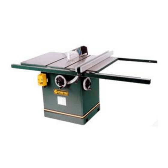
- Page 1 OWNER’S MANUAL B2062L – 12” Table Saw...
-
Page 2: Table Of Contents
TABLE OF CONTENTS GENERAL SAFETY INSTRUCTIONS PAGE 3 SPECIFIC SAFETY INSTRUCTIONS PAGE 4 B2062L Features Page 5 Unpacking Page 6 Unpacking, Continued Page 7 Assembly Extension Tables Page 9 Blade Guard & Splitter Page 9 Installing the Blade Guard, Continued... -
Page 3: General Safety Instructions
GENERAL SAFETY INSTRUCTIONS EXTREME CAUTION SHOULD BE USED IN OPERATING ALL POWER TOOLS. KNOW YOUR POWER TOOL, BE FAMILIAR WITH ITS OPERATION. READ OWNER’S MANUAL PRACTICE SAFE USAGE PROCEDURES AT ALL TIMES. CONNECT your machine ONLY to the matched and specified power source. -
Page 4: Specific Safety Instructions
ALWAYS make sure that your saw is in a stable position. Cutting heavy, long stock may alter the stability of the B2062L. In the event that this may occur, the saw should be firmly bolted to the floor. - Page 5 Craft Excellence. By following the instructions and procedures laid out in this owner’s manual, you will receive years of excellent service and satisfaction. The B2062L is a professional tool and like all power tools, proper care and safety procedures should be adhered to.
-
Page 6: Unpacking
Open all cartons and set the parts to one side being careful to see that all cartons are completely empty before discarding them. Your B2062L table saw is shipped with a protective coating on most exposed cast-iron surfaces and this coating should be removed prior to assembly. Using a cloth and mineral spirits, wipe the surfaces clean. -
Page 7: Unpacking Continued
UNPACKING Continued ‘T’ Slot Mitre Gauge. Blade Guard, Splitter and safety push sticks. Other components included with the saw carton are 2- cast-iron Extension Tables, Rip Fence Rails and the Rip Fence. -
Page 8: Assembly
ASSEMBLY Your B2062L Table Saw is shipped in an almost fully assembled condition, the components remaining to be assembled are: 1. Cast-iron Extension Tables. 2. Blade Guard & Splitter. 3. Rip Fence Rails. 4. Rip Fence. 5. Hand Wheels Place your table saw on a solid floor surface before proceeding with the assembly and be sure that the castors on the mobile base are locked. -
Page 9: Installing The Blade Guard, Continued
ASSEMBLY Continued The threads of the guard are machined eccentric. This allows adjustment of the back of the blade guard. By rotating the support rod, the rod will move off centre, allowing for different positions. Alignment and final tightening of the support rod will occur when the blade guard is installed. Installing the Blade Guard 1. -
Page 10: Arbor Extension
ASSEMBLY Continued 5. Align the front of the spreader to the blade. 6. To adjust the height of the front of spreader loosen the front attachment bolt and position the spreader up or down. The height should be such as to allow the guard to contact the table surface. -
Page 11: Hand Wheels
The handles for these wheels are simply threaded into the threaded holes provided. Blade Alignment Your B2062L Craftex Table Saw is shipped from the factory with the saw table adjusted so that the mitre gauge slots are parallel to the saw blade. - Page 12 ASSEMBLY Continued Adjusting the Saw Table for Parallel Should an adjustment be necessary, proceed as follows: 1. Refer to the Schematic Diagram on page 25. 2. Loosen the 10mm hex head cap screws, which fasten the cast-iron table to the sheet metal cabinet. 3.
-
Page 13: Rip Fence Assembly
ASSEMBLY Continued Rip Fence Assembly The B2062L Tilting Arbor Saw is equipped with a precision “T” Type, Lever Fence incorporating a Micro-Adjustment and a Magnifying Cursor Lens. Install the front rail to the leading edge of the saw table using four pan- head screws and lock washers provided. - Page 14 ASSEMBLY Continued Measuring Scale Indicator Adjustments The measuring scale indicator in both inches and metric have been set at the factory and should not require adjustments. However, in the event that it does, do the following; Check to see that the ‘0’ indicator is correct on the right side of the saw blade.
-
Page 15: Electrical Diagram & Wiring
ELECTRICAL DIAGRAM & WIRING Important: The B2062L Magnetic Power Switch is already fully wired to the Junction Box. SINGLE PHASE WIRING The motor to starter line cord is four conductors. The green conductor is ground while the other three are power conductors. Single-phase power uses only three of these conductors. - Page 16 ELECTRICAL DIAGRAM & WIRING...
-
Page 17: Operation
Lock the hand wheel by rotating the lock knob. Do not over-tighten. Mitre Gauge Adjustment The mitre gauge supplied with the B2062L table saw is equipped with individually adjustable index stops at 90 degrees and 45 degrees both left and right. Adjustment to these stops can be made by loosening the locking nut and tightening or loosening the three adjusting screws. -
Page 18: Maintenance
MAINTENANCE Before performing any maintenance be certain that the saw is disconnected from any power source. * Clean off any preservative on the saw components with mineral spirits or varsol and wipe dry. *Avoid getting any of the cleaning fluid on rubber parts as it may permanently damage them. - Page 19 PARTS LIST & SCHEMATIC DRAWINGS Ref. Description Part No. Quantity Handle 1086.00 Washer, 10mm 1087.00 1088.00 Gauge 1089.00 Round Head Screw, 5mm - 1090.00 .80 x 20 Indicator 1091.00 Mitre Gauge Stop 1092.00 Set Screw, 6mm – 1.0 x 6 0964.00 Set Screw, 6mm –...
- Page 20 PARTS LIST & SCHEMATIC DRAWINGS Blade Guard Schematic Ref. No. Part No. Description Quantity Push Nut 1069.00 Clear Blade Guard 1070.00 Guard Support 1071.00 1072.00 Spring 1073.00 Spreader 1074.00 Spacer 1075.00 1076.00 Anti-kickback Pawl 1077.00 Snap Ring 1078.00 1079.00...
-
Page 21: Fence Schematic & Parts List
FENCE SCHEMATIC & PARTS LIST Description Part No. Qty. Ref. Description Part No. Qty. Front Rail 2001.00 Lock Knob 2011.00 Rear Rail 2002.00 Cam Lever 2012.00 Guide Rail 2003.00 2013.00 Measure Scale 2004.00 Clamp Shoe 2014.00 Hex Screw 2219.00 Lock Nut 2211.00 M8x16mm Lock Washer... -
Page 22: Main Mechanism Schematic
MAIN MECHANISM SCHEMATIC... -
Page 23: Main Mechanism Parts List
MAIN MECHANISM PARTS LIST Ref. No Description Part No. Qty. Washer 0950.00 Bushing 0951.00 Bushing 0951.00 Arbor Nut 1” I.D. 0952.00 Blade Flange 1” I.D. 0953.00 Arbor Extension for 1” O.D. Blade 0954.00 Arbor 0955.00 Bearing 0956.00 Socket Head Bolt – 1.25 x 25 0957.00 Setscrew –... - Page 24 Washer, 8mm 0997.00 Front Support Bracket 0998.00 Socket Head Bolt, 6mm – 1.0 x 12 0963.00 Lock Washer, 12mm 1000.00 Hex Nut, 12mm – 1.75 1001.00 Socket Head Bolt, 10mm – 1.5 x 25 1002.00 1003.00 Rear Trunion Bracket 1004.00 1005.00 1006.00 Setscrew, 6mm –...
- Page 25 TABLE & BASE ASSEMBLY SCHEMATIC DRAWING...
- Page 26 TABLE & BASE ASSEMBLY PARTS LIST REF. NO. DESCRIPTION Part No. Qty. Extension Table 1037.00 Hex Head Bolt, 10mm – 1.5 x 35 0962.00 Lock Washer, 10mm 0963.00 Blade Insert 1042.00 Setscrew, 6mm – 1.0 x 8 1043.00 Table 1044.00 Base 1045.00 Indicator Plate...
-
Page 27: Busy Bee Locations
RETURNS, REPAIRS AND REPLACEMENTS To return, repair, or replace a Craftex product, you must visit the appropraite Busy Bee Tools showroom. Craftex is a brand of equipment that is exclusive to Busy Bee Tools. For replacement parts directly from Busy Bee Tools, for this machine, please call 1-800-461-BUSY(2879), and have your credit card and part number handy. - Page 28 BUSY BEE TOOLS - - - SHOWROOMS -Coast to Coast Head Office 355 Norfinch Drive, North York, Ontario, M3N 1Y7 Tel. - 416-665-8008, Fax – 416-665-8337 Vancouver 30 Braid Street, New Westminister, British Columbia, V3L 3P3 Tel. – 604-517-3922, Fax – 604-517-8272 Mississauga 6325 Dixie Rd.
Need help?
Do you have a question about the B2062L and is the answer not in the manual?
Questions and answers