Panasonic AW-RP655N Operating Instructions Manual
Multi-function controller
Hide thumbs
Also See for AW-RP655N:
- Mechanical parts (16 pages) ,
- Operating instructions manual (44 pages)

Related Manuals for Panasonic AW-RP655N


Summary of Contents for Panasonic AW-RP655N
- Page 1 Multi-Function Controller AW-RP655N Before attempting to connect, operate or adjust this product, please read these instructions completely. Printed in Japan F1105S0 VQTB0000...
-
Page 2: Rack Mounting Adapters (5U)
Safety precautions FCC Note: CAUTION This equipment has been tested and found to comply RISK OF ELECTRIC SHOCK with the limits for a class A digital device, pursuant to DO NOT OPEN Part 15 of the FCC Rules. These limits are designed to provide reasonable protection against harmful CAUTION: TO REDUCE THE RISK OF ELECTRIC SHOCK, interference when the equipment is operated in a... - Page 3 Safety precautions IMPORTANT SAFETY INSTRUCTIONS Read these operating instructions carefully before using the unit. Follow the safety instructions on the unit and the applicable safety instructions listed below. Keep these operating instructions handy for future reference. 1) Read these instructions. 10) Protect the power cord form being walked on or pinched particularly at plugs, convenience 2) Keep these instructions.
-
Page 4: Table Of Contents
Contents Introduction ............... 4 Setting the travel range (limiters) of the pan/tilt head ..20 Genlock adjustment ............22 Accessories ............... 4 Total pedestal adjustment ..........25 Parts and their functions ..........5 White balance adjustment ..........26 Control panel ..............5 Black balance adjustment .......... -
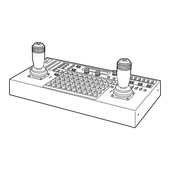
Page 5: Parts And Their Functions
Parts and their functions $ Control panel 7 8 9 1 OPERATE lamp LOCK: The lens iris is fixed at the position where it was adjusted manually, and the IRIS button’s This lamp will come on when power is supplied to this lamp flashes. - Page 6 Parts and their functions < > : GAIN [AUTO/MAN] button = WHITE BAL [A/B/ATW] buttons This is used to select the camera’s gain control mode in These are used to select the camera’s white balance the pan/tilt head system currently selected. adjustment in the pan/tilt head system currently selected.
- Page 7 Parts and their functions J K L M N O P ? ABC button D Menu setting control (main) This is used to automatically adjust camera’s black This is used to select the item or change the value of the balance in the pan/tilt head system currently selected.
- Page 8 Parts and their functions J K L M N O P J LAMP button N EXT (AF) button This controls the ON and OFF of the halogen lamp which EXT (AF) Button is connected to the pan/tilt head system currently If a lens with an extender function is used in the selected selected.
- Page 9 Parts and their functions Q START POINT button W MEMORY button Press this to set the position at which the tracing memory This is pressed when the pan/tilt head system’s settings is to be started. are to be entered as a preset memory into one of the TRACING/PRESET MEMORY buttons [1] through [50].
- Page 10 Parts and their functions Y ZOOM lever, FOCUS/IRIS dial \ PAN/TILT lever, FOCUS/IRIS dial These are used to adjust the lens zoom in the pan/tilt These are used to adjust the direction of the pan/tilt head head system currently selected. in the pan/tilt head system currently selected.
- Page 11 Parts and their functions _ TALLY lamps [1] to [5] b SPEED button When tally signals are input to TALLY connectors [1] This is used to select the control (pan, tilt, zoom, focus, through [5] on the main unit, the lamps with the numbers iris) speed of the pan/tilt head system currently selected.
-
Page 12: Rear Connector Panel
Parts and their functions $ Rear Connector Panel c GND terminal f REMOTE/SERVICE connector Use to ground the unit. A personal computer or other external equipment is connected here when a pan/tilt head system is to be d DC12V IN terminal controlled by these equipments. - Page 13 Parts and their functions i TERMINATION switch k TO PAN/TILT HEAD 1/EXT terminal Termination switch for the control signal communicating • Functions as the pan/tilt head’s connection terminal with the control panel. when the EXT CONTROL OUT is set to OFF on the •...
- Page 14 Parts and their functions l TO PAN/TILT HEAD 2 to 5 terminal • Functions as the pan/tilt head’s connection terminal when EXT CONTROL OUT is set to OFF on the controller setting menu (see page 36). Connect a 10BASE-T straight cable (UTP category 5) to the pan/tilt head’s IP/RP terminal.
-
Page 15: Connections
Connections Turn off the power of all components before proceeding with the connections. O Use the AW-PS505A (sold separately) AC adapter for this unit and the AW-PS300A (sold separately) for the pan/tilt head. O Use a DC power cable (which has a nominal cross- sectional area of at least 1.25 mm and which complies with the Electrical Appliance and Material Control Law) to... - Page 16 Connections Zoom lens Convertible camera Camera cable (supplied) DC cable (UL Type SPT-2 2!16 AWG or 10BASE-T (equivalent to UTP UL Type NISPT-2 2!16 AWG, category 5) straight cable to be locally purchased) AC adapter: AW-PS300A Coaxial cable (BELDEN 8281) Base connector front panel Coaxial cable (BELDEN 8281)
- Page 17 Connections When using the AW-PH300, AW-PH300A, AW-PH500 or the AW-PH600 pan/tilt head The control signal from this unit must be converted from RS-422 to RS-232C. Consult with your dealer concerning the RS-232C/RS-422 converter and connecting cable. Shown below is an example of the connections performed by the RS-232C/RS-422 converter. Pan/tilt head: RS-232C/RS-422 converter Cable length:...
- Page 18 Connections Example of system configuration Halogen lamp Pan/tilt head system AC adapter: Genlock signal generator AW-PS300A Video signal G/L signal AW-RC400 Cable compensation unit Pan/tilt head/camera control signal 10BASE-T Inter-communications headset AC adapter: Color monitor AW-RP655 AW-PS505A (75Ω terminator) Multi-function controller Set ID to [Main] Set TERMINATION to [OFF] Switcher, special...
-
Page 19: Operation
Operation $ Turning on the power $ Setting the camera model 1. Set all the power switches of the connected components These steps must be taken without fail when using the and the power switch of the AC adapter to ON. AW-PH300, AW-PH300A or AW-PH600 pan/tilt head. -
Page 20: Adjusting The Minimum Start Speed Of The Pan/Tilt Head
Operation $ Adjusting the minimum start $ Adjusting the backlash compensation speed of the pan/tilt head Play in the gears may give rise to backlash when the pan/tilt head is moved. This adjustment serves to provide When the pan/tilt head is to be operated manually using the compensation for reducing the amount of this backlash. -
Page 21: Adjusting The Minimum Start Speed Of The Lens Zoom
Operation $ Adjusting the minimum start $ Setting the travel range (limiters) speed of the lens zoom of the pan/tilt head Perform this adjustment to ensure that the lens zoom will Depending on where it has been installed, there may be function smoothly in response to the angle to which the obstacles within the travel range of the pan/tilt head system zoom lever is tilted when it is used to zoom the lens. -
Page 22: Genlock Adjustment
Operation $ Genlock adjustment If a camera is to be synchronized with an external signal for use, genlock adjustment must be performed for the camera 4. Set the left-most limit position in the travel range. and other equipments. 1 Operate the PAN/TILT lever on the control panel to Either the black burst or VBS (video, burst and sync) signal rotate the camera to the position which is to serve as is used for the external sync signal. - Page 23 Operation Horizontal phase adjustment 1. Select the pan/tilt head system using the CONTROL/PREVIEW MONITOR OUT SEL button. 2. Connect the external synchronizing signal and the video signal from the currently selected pan/tilt head system (when using the cable compensation unit, the corresponding Y/VIDEO OUT terminal) to the 2CH oscilloscope.
- Page 24 Operation Subcarrier phase adjustment The subcarrier phase adjustment must be performed, when 8. Align the phase of the color bar signals from the camera composite signals have been set as the video input signals with the phase of the color bar signals serving as the and the pictures are to be switched by a video switcher or reference.
-
Page 25: Total Pedestal Adjustment
Operation $ Total pedestal adjustment When more than one camera is to be used, the black level (pedestal level) of the pictures shot by each of the cameras must be brought into alignment. 1. Select the pan/tilt head system using the CONTROL/PREVIEW MONITOR OUT SEL button. -
Page 26: White Balance Adjustment
Operation $ White balance adjustment The white balance must be adjusted when the equipment is Manual adjustment of white balance used for the first time, when it has not been used for a 1. As with the procedure for automatic adjustment, select prolonged time or when the lighting conditions or brightness the pan/tilt head system using the CONTROL/PREVIEW has changed. -
Page 27: Black Balance Adjustment
Operation $ Black balance adjustment The black balance must be adjusted when the equipment is Manual adjustment of black balance used for the first time, when it has not been used for a prolonged time, when the ambient temperature has changed 1. -
Page 28: Tracing Memory Settings
Operation $ Tracing memory settings The multi-function controller is equipped with a tracing memory function for entering the series of settings with which pan/tilt head systems is operated. The tracing memories are entered into TRACING/PRESET MEMORY buttons 1 through 10. Setting the entry time (memory length) and number of memories 1. - Page 29 Operation Entering the tracing memory data 1. Select the pan/tilt head system using the 8. The entry in the tracing memory commences as soon as CONTROL/PREVIEW MONITOR OUT SEL button. the pan, tilt, zoom, focus, iris or white balance mode selection is initiated so proceed with the entry operation.
- Page 30 Operation Recalling tracing memory data Making changes to the tracing memory 1. Select the pan/tilt head system using the 1. Select the pan/tilt head system using the CONTROL/PREVIEW MONITOR OUT SEL button. CONTROL/PREVIEW MONITOR OUT SEL button. 2. Press the button in which the tracing memory data to be 2.
- Page 31 Operation Deleting tracing memory data 1. Select the pan/tilt head system using the CONTROL/PREVIEW MONITOR OUT SEL button. 2. While holding down the RESET button, press the buttons in which the tracing memory data to be deleted has been entered. The lamps of the buttons in which tracing memory data has been entered (TRACING/PRESET MEMORY buttons 1 through 10) come on when the RESET...
-
Page 32: Preset Memory Settings
Operation $ Preset memory settings The multi-function controller is equipped with a preset memory function for entering the positions and settings with which the pan/tilt head system is to shoot. Preset memory data is entered into TRACING/PRESET MEMORY buttons 1 through 50. Entering preset memory data 1. -
Page 33: Setting Menus
Setting menus G/L SETTING H PHASE [– 0] SC PHASE [COARSE: 1, FINE: – 0] With the COARSE setting, it is not possible to switch the speed at which the setting value changes when the menu setting control is pressed. CONTROLLER SETTING BUZZER SET [ON]... - Page 34 Setting menus (AW-E300/AW-E300A/AW-E600/AW-E800A) CAMERA SETTING SCENE [USER] USER HALOGEN SHUTTER [OFF] SHUTTER [OFF] DETAIL [HIGH] DETAIL [HIGH] PICTURE LEVEL [± 0] PICTURE LEVEL [± 0] LIGHT PEAK/AVG LIGHT PEAK/AVG LIGHT AREA [TOP CUT] LIGHT AREA [TOP CUT] S/S FREQUENCY [60.34 Hz] S/S FREQUENCY [60.34 Hz] CHROMA LEVEL...
- Page 35 Setting menus (AW-E350/AW-E650/AW-E655/AW-E750) CAMERA SETTING SCENE [USER] USER HALOGEN SHUTTER [OFF] SHUTTER [OFF] DETAIL [HIGH] DETAIL [HIGH] PICTURE LEVEL [± 0] PICTURE LEVEL [± 0] LIGHT PEAK/AVG LIGHT PEAK/AVG LIGHT AREA [TOP CUT] LIGHT AREA [TOP CUT] S/S FREQUENCY [60.34 Hz] S/S FREQUENCY [60.34 Hz] CHROMA LEVEL...
- Page 36 Setting menus G/L SETTING (genlock adjustment) CONTROLLER SETTING (controller menu setting) menu H PHASE (–206 to +49) BUZZER SET (ON/OFF) This item is used to adjust the horizontal phase during This is used to set the buzzer contained inside the control genlock.
- Page 37 Setting menus P/T SETTING (pan/tilt head setting) menu PAN DIRECTION (NORMAL/REVERSE) IRIS DIRECTION (NORMAL/REVERSE) This item is used to select the operations in the horizontal This item is used to select the focus operations of the lens direction of the pan/tilt head system which are to be which are to be performed by operating the dials on the top performed by operating the PAN/TILT lever.
- Page 38 Setting menus SPEED WITH ZOOM POS. (OFF, 1, 2) CAMERA SETTING menu When 1 or 2 is selected as this item’s setting, the pan/tilt operation of the pan/tilt head system is slowed down so that The operation items differ depending on the type of camera the pan/tilt position will be more easily aligned when the lens or pan/tilt head used and the optional card installed.
-
Page 39: Attaching The Rack Mounting Adapters
Attaching the rack mounting adapters To install the main unit in a rack, use the rack mounting adapters and mounting screws (M4a8 mm) supplied. Replacement of consumable parts O Battery replacement O Joystick replacement The battery has a life of 5 years. Replace the battery The joystick is a consumable part. -
Page 40: Appearance
Appearance Unit: inch (mm) 8-11/16 (220) -
Page 41: Specifications
Specifications Power supply: DC 10.8 V to DC 16 V Power consumption: 9.0 W 1 indicates safety information. $ General $ Output connectors Ambient operating temperature CONTROL OUT TO PAN/TILT HEAD [1/EXT2 to 5] 14°F to 122°F (–10°C to +50°C) connectors RJ45 a5, control signal output for pan/tilt heads Storage temperature... - Page 42 PANASONIC BROADCAST & TELEVISION SYSTEMS COMPANY UNIT COMPANY OF PANASONIC CORPORATION OF NORTH AMERICA Executive Office: One Panasonic Way 4E-7, Secaucus, NJ 07094 (201) 348-7000 EASTERN ZONE: One Panasonic Way 4E-7, Secaucus, NJ 07094 (201) 348-7621 Southeast Region: 1225 Northbrook Parkway, Ste 1-160, Suwanee, GA 30024 (770) 338-6835...
Need help?
Do you have a question about the AW-RP655N and is the answer not in the manual?
Questions and answers