Table of Contents
Advertisement
Quick Links
Advertisement
Chapters
Table of Contents
Troubleshooting

Related Manuals for Omron C200HW-PRM21


Summary of Contents for Omron C200HW-PRM21
- Page 1 Cat. No. W349-E2-2 C200HW-PRM21 PROFIBUS-DP Master Unit OPERATION MANUAL...
- Page 5 C200HW-PRM21 PROFIBUS-DP Master Unit Operation Manual Produced May 2000...
- Page 7 OMRON. No patent liability is assumed with respect to the use of the information contained herein. Moreover, because OMRON is constantly striving to improve its high-quality products, the information contained in this manual is subject to change without notice.
-
Page 9: Table Of Contents
1-4 PROFIBUS-DP characteristics..........................4 1-5 Device Data Base files .............................8 1-6 Profiles ..................................8 INSTALLATION.................. 9 2-1 Physical layout of the unit ............................10 2-2 Mounting the C200HW-PRM21 ..........................13 2-3 Setting up a network...............................14 SPECIFICATIONS AND PERFORMANCE........17 3-1 Overall Specifications ............................18 3-2 Performance ................................20 CONFIGURATOR ................ - Page 10 Appendices ....................93 Appendix A Tips and sample programs ....................93 Appendix B GSD file for C200HW-PRM21 ..................101 Appendix C CS1 PLC series compatibility .....................103 Index ......................105 Revision History ..................107 viii...
- Page 11 Section 1 gives a brief description of PROFIBUS-DP. Section 2 describes the installation of the C200HW-PRM21. Section 3 describes the overall specifications and the communication performance of the Unit. Section 4 describes the software for configuring the PROFIBUS-DP network.
-
Page 13: Precautions
PRECAUTIONS This section provides general precautions for using the PROFIBUS-DP Master Units, Programmable Controllers, and related devices. The information contained in this section is important for the safe and reliable application of the PROFIBUS-DP Master Units. You must read this section and understand the information contained before attempting to set up or operate a PROFIBUS-DP Master Unit and PLC system. -
Page 14: Intended Audience
! WARNING specified purpose and under the specified conditions, especially in applications that can directly or indirectly affect human life. You must consult with your OMRON representative before applying a PLC system to the above mentioned applications. Safety Precautions Never attempt to disassemble any Units while power is being supplied. Doing ! WARNING so may result in serious electrical shock or electrocution. -
Page 15: Application Precautions
Application Precautions The operating environment of the PLC System can have a large effect on the Caution longevity and reliability of the system. Improper operating environments can lead to malfunction, failure, and other unforeseeable problems with the PLC System. Be sure that the operating environment is within the specified conditions at installation and remains within the specified conditions during the life of the system. -
Page 16: Ec Directives
generated by broken signal lines or momentary power interruptions. • Provide external interlock circuits, limit circuits, and other safety circuits in addition to any provided within the PLC to ensure safety. EC Directives PROFIBUS-DP Master Units that meet EC directives also meet the common emission standard (EN50081-2). -
Page 17: Profibus-Dp
1 PROFIBUS-DP This section gives a brief description of PROFIBUS-DP. 1-1 Introduction................................2 1-2 Protocol architecture ..............................2 1-3 Device types................................4 1-4 PROFIBUS-DP characteristics ..........................4 1-4-1 Bus Access Protocol ............................4 1-4-2 Data throughput ...............................5 1-4-3 Diagnostics functions ............................6 1-4-4 Protection mechanisms.............................6 1-4-5 Network states ..............................7 1-5 Device Data Base files ...............................8 1-6 Profiles ..................................8... -
Page 18: Introduction
Introduction Section 1-1 Introduction PROFIBUS is a vendor-independent, open fieldbus standard for a wide range of applications in manufacturing, process and building automation. Vendor Multi-vendor independence and openness are guaranteed by the PROFIBUS standard EN 50170. With PROFIBUS, devices of different manufacturers can Standard communicate without special interface adjustments. - Page 19 Section 1-2 Protocol architecture DP-Profiles DP-Extensions User Interface Layer DP Basic Functions (7) Application Layer (6) Presentation Layer (5) Session Layer NOT DEFINED (4) Transport Layer (3) Network Layer (2) Data Link Layer Fieldbus Data Link (FDL) (1) Physical Layer RS-485 / Fibre Optics PROFIBUS-DP uses layers 1 and 2, and the user interface.
-
Page 20: Device Types
Passive stations send messages to the master when requested to do so. Slaves are also called passive stations. The C200HW-PRM21 is a DPM1 device. PROFIBUS-DP characteristics 1-4-1 Bus Access Protocol Layer 2 The bus access protocol is implemented by layer 2. -
Page 21: Data Throughput
Section 1-4 PROFIBUS-DP characteristics The configuration shows three active stations (masters) and six passive stations (slaves). The three masters form a logical token ring. When an active station receives the token telegram, it can perform its master role for a certain period of time. -
Page 22: Diagnostics Functions
Section 1-4 PROFIBUS-DP characteristics Bus cycle time vs number of slaves 25.0 20.0 1500 15.0 3000 12000 10.0 Slaves Conditions: Each slave has 2 bytes of input data and 2 bytes of output data. 1-4-3 Diagnostics functions Extensive diagnostics The extensive diagnostic functions of PROFIBUS-DP enable fast location of faults. -
Page 23: Network States
PROFIBUS-DP characteristics Section 1-4 can only be performed by the authorised master. For all other masters, the slaves offer an image of their inputs and outputs which can be read from any master, even without access rights. 1-4-5 Network states PROFIBUS-DP distinguishes four different states. -
Page 24: Device Data Base Files
PRM21, named OC_1656.GSD, is provided with the configuration software. Section 4 will describe the configurator package SyCon, which is used for configuration of the C200HW-PRM21, in more detail. Profiles To enable the exchange of devices from different vendors, the user data has Exchanging devices to have the same format. -
Page 25: Installation
2 Installation This section describes the installation of the C200HW-PRM21 2-1 Physical layout of the unit ............................10 2-1-1 LEDs................................10 2-1-2 Rotary Switch ..............................10 2-1-3 BUS Connector...............................11 2-1-4 Configurator Connector ..........................12 2-1-5 Termination Switch............................13 2-2 Mounting the C200HW-PRM21 ..........................13 2-3 Setting up a network..............................14 2-3-1 Fieldbus cabling .............................14... -
Page 26: Physical Layout Of The Unit
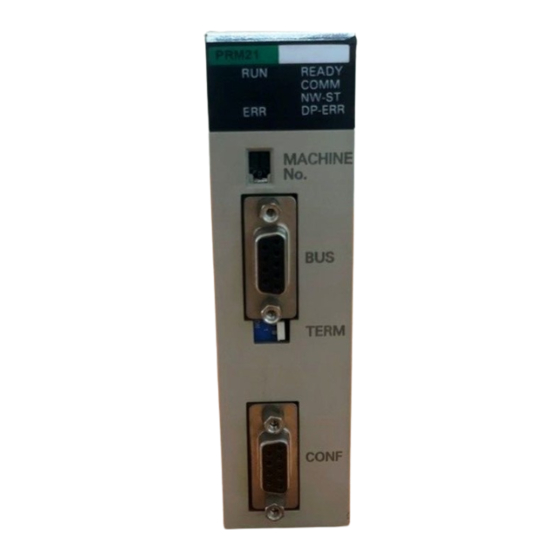
9-pin female sub-D connectors, and the bus termination switch. 2-1-1 LEDs The C200HW-PRM21 has 6 indicator LEDs. The two LEDs on the left side give a status indication of the unit in general. The four LEDs on the right side are related to the status of the PROFIBUS-DP network Refer to section 5-4 for a detailed (functional) description of the LEDs. -
Page 27: Bus Connector
Special I/O Unit connected to the PLC. If the same unit number is used for the C200HW-PRM21 and another Special I/O Unit, an I/O Unit Over error will occur in the PLC and it will not be possible to start up the PROFIBUS-DP Network. -
Page 28: Configurator Connector
The pin assignment of this connector is the same as the that of the RS-232C port provided on most C200H-series CPUs. This enables the use of the same serial communication cable for both the CPU and the C200HW-PRM21. The wiring of the RS-232C cable is shown in the picture below. -
Page 29: Mounting The C200Hw-Prm21
DGND Mounting the C200HW-PRM21 The PROFIBUS-DP Master Unit (C200HW-PRM21) can be mounted to the CPU Rack or Expansion I/O Rack of any CS1, C200HX, -HG, -HE, or -HS PLC. Refer to the PLC’s Installation Guide for details on mounting Units. -
Page 30: Setting Up A Network
32 stations are used, repeaters must be used to link the individual bus segments. The maximum number of stations that can be connected to a C200HW-PRM21 is 124. The standard EN 50170 specifies to use line type A of shielded twisted pair... - Page 31 Section 2-3 Setting up a network The connector plug to be used on the C200HW-PRM21 is a 9-pin male sub- Fieldbus connector D, preferably with a metal case, and a facility to connect the shield of the cable to the case. The cable should at least be connected to pin 3 (B-line) and pin 8 (A-line) of the connector.
-
Page 32: Configuring The Fieldbus
For more details about the configurator refer to section 4. After entering the configuration, it must be downloaded to the master unit. A Downloading configuration serial COM-port of the PC is to be connected to the C200HW-PRM21 via the prescribed RS-232C cable. -
Page 33: Specifications And Performance
3 Specifications and Performance This section describes the overall specifications and the communication performance of the Unit 3-1 Overall Specifications ..............................18 3-2 Performance ................................20 3-2-1 Fieldbus cycle time ............................20 3-2-2 PLC cycle time..............................24 3-2-3 I/O response time in asynchronous mode.......................25 3-2-4 I/O response time in synchronous mode......................27... -
Page 34: Overall Specifications
Section 3-1 Overall Specifications Overall Specifications C200HS C200HE/HG/HX, CS1 Model code C200HW-PRM21 Maximum. number of Master C200HE-CPU11/32/42 Units C200HG-CPU33/43 (with user defined I/O mapping) C200HX-CPU34/44 C200HG-CPU53/63 C200HX-CPU54/64 CS1-series Master Unit mounting position CPU Rack or Expansion I/O Rack (classified as Special I/O Unit) Unit cannot be mounted to SYSMAC BUS Slave Racks. - Page 35 Section 3-1 Overall Specifications The following diagram shows the dimensions of the Master Unit. Refer to the Dimensions PLC’s Installation Guide for the dimensions of the Unit when it is mounted to the Backplane. (All dimensions are in mm.)
-
Page 36: Performance
Section 3-2 Performance Performance 3-2-1 Fieldbus cycle time This section gives a simplified method of fieldbus cycle time calculations. Refer to EN 50170 for a more detailed calculation of the fieldbus cycle time. The fieldbus cycle time with only one master is approximately: = (ns + nr) x t GAP_REQ where: ns... - Page 37 Performance Section 3-2 Message cycle time A message consists of an action frame (request or send/request frame) and a reply frame (acknowledge or response frame). The message cycle time is composed of the frame transmission times, the transmission delay times, the station delay time and the bus idle time.
- Page 38 Performance Section 3-2 If the station is not present, the master stops waiting for an answer after the slot-time (one of the bus parameters). The check time in this case is: GAP_REQ REQ_FRAME SLOT IDLE = 6 x 11 + 100 + 37 t = 203 t The formulas are based upon the following assumptions: •...
- Page 39 Section 3-2 Performance Bus cycle time vs number of slaves 25.0 20.0 1500 15.0 3000 12000 10.0 Slaves The second figure shows the effect of the number of masters on the bus cycle time. The values of the parameters are: = nm (each master has one slave) = variable on the x-axis Baud rate...
-
Page 40: Plc Cycle Time
The total I/O refresh time depends on the types of units that are mounted on the Backplane(s). Not all units refresh the same amount of data. The I/O refresh time of the C200HW-PRM21 depends on the number of data areas and the number of I/O data words that have been mapped. -
Page 41: I/O Response Time In Asynchronous Mode
Section 3-2 Performance 3-2-3 I/O response time in asynchronous mode In asynchronous data transfer mode, the fieldbus cycle is not synchronised with the PLC cycle; fieldbus cycles are triggered continuously, independent of the PLC cycle. Minimum I/O response time The figure below shows the minimum I/O response time in asynchronous mode. - Page 42 Section 3-2 Performance The figure below shows the maximum I/O response time in asynchronous Maximum I/O response time mode. The figure shows the timing at the PLC, the timing at the Master Unit, the timing at the slave input and the timing at the slave output. : The Input Slave’s ON (OFF) delay : The Output Slave’s ON (OFF) delay : The Fieldbus cycle time...
-
Page 43: I/O Response Time In Synchronous Mode
Performance Section 3-2 3-2-4 I/O response time in synchronous mode In synchronous data transfer mode, the fieldbus cycle is triggered immediately following the I/O refresh of the PLC. If the fieldbus cycle has not finished before the start of the I/O refresh, the fieldbus cycle is not triggered until after the next I/O refresh. - Page 44 Section 3-2 Performance The figure below shows the maximum I/O response time in synchronous Maximum I/O response time mode. The figure shows the timing at the PLC, the timing at the Master Unit, the timing at the slave input and the timing at the slave output. : The Input Slave’s ON (OFF) delay : The Output Slave’s ON (OFF) delay : The Poll cycle time of the respective master...
-
Page 45: Configurator
4 Configurator This section describes the configuration software package, required to set up a PROFIBUS-DP network 4-1 General ...................................30 4-1-1 Introduction ..............................30 4-1-2 System Requirements ............................30 4-2 Setup ..................................31 4-2-1 Installation ..............................31 4-2-2 Uninstall .................................31 4-3 Operation................................32 4-3-1 PROFIBUS-DP configuration ........................33 4-3-2 Device database..............................33 4-3-3 Bus configuration............................34 4-3-4 Device configuration............................36... -
Page 46: General
Monitoring the PROFIBUS system status. • Troubleshooting communication problems. It is not possible to set up the C200HW-PRM21 without this configuration software. Once the configuration data has been downloaded into the Unit, the software package is no longer required during normal operation. -
Page 47: Setup
Since SyCon V2.620 serves as PROFIBUS-DP configurator for Master devices of several manufacturers, it is necessary to make the correct choices during installation to provide the correct settings for the C200HW-PRM21: The license code is will be provided on the next installation screen. -
Page 48: Operation
Section 4-3 Operation Operation Menu The operation of the configurator is menu-driven. The functions located under the main menu items are: • File Create, load and save PROFIBUS-DP configuration files. • Print configuration data. • Copy GSD files to the device database folder. •... -
Page 49: Profibus-Dp Configuration
PROFIBUS-DP network. The GSD file for the C200HW-PRM21 is named OC_1656.GSD, and is provided with the configurator software package (see also Appendix B). For each slave that needs to be configured, a specific GSD file must be provided by the manufacturer of the device. -
Page 50: Bus Configuration
Master Unit. A list of masters whose GSD files are found in the Device Database folder is shown. Select the C200HW-PRM21 from the list of available masters, and click the ‘Add>>’ button: Selecting the added Unit from the list ‘Selected Masters’ allows you to set its bus address before clicking ‘OK’. - Page 51 Section 4-3 Operation After assigning the Master, the corresponding slaves can be added. Slave selection To add a slave, select ‘Insert – Slave’, or click the icon: and select a row in the configuration window. If a unit is already on the selected row, a new row will be inserted above it.
-
Page 52: Device Configuration
Section 4-3 Operation 4-3-4 Device configuration Device configuration comprises the following steps: 1, 2, 3... Station address assignment. Slave module configuration. Mapping of the slaves’ I/O data to the Unit’s buffer areas. Setting the slaves’ User Parameter Data. The configurator offers the option to automatically assign the I/O data of each Auto-addressing slave to a location in the Unit’s buffer areas. - Page 53 Words under ‘I Addr.’ and ‘O Addr.’. Manually entered offset assignments are automatically checked before being downloaded into the C200HW-PRM21. See 4-3-8, ‘Download’. The example below shows: • One module (Slot=1) which has two indexed sub-modules (Idx=1, Idx=2) •...
- Page 54 Section 4-3 Operation Depending on the type of slave, specific parameter information may need to Slave Parameter Data be transferred to the slave at initialisation. The ‘Parameter Data’ dialog box allows verification and adjustment of these parameters in several ways. The initial dialog shows all parameter data in hexadecimal notation.
-
Page 55: Group Membership
Section 4-3 Operation 4-3-5 Group membership Group Definitions Via the menu item ‘Settings – Group membership’, up to 8 groups of slaves can be defined as targets for PROFIBUS-DP Global Control Commands. The Group Membership dialog box allows definition of group names, and of supported functions (Freeze / Sync) per group, For more information on the execution of Freeze / Sync functions, see 5-3-1, Control words’. -
Page 56: Check I/O Assignments
Section 4-3 Operation 4-3-6 Check I/O assignments After the slaves have been configured, it is possible to obtain an overview of all configured devices and their data allocation in the I/O buffers, by the menu items ‘View – Device table’ and ‘View – Address table’. The Device table shows all configured slaves, in the order in which they were Device table defined. - Page 57 Operation Section 4-3 2. Sort according to data address. This sorting method is most convenient to find which slave’s data is available at a given buffer location. Sorted by data address. The allocation of each Byte of each module can be checked by clicking the button ‘Address Overview…’.
-
Page 58: Bus Parameters
All standardised PROFIBUS-DP values from 9.6 kbit/s to 12 Mbit/s are supported by the C200HW-PRM21. A change of baud rate will recalculate all parameters to a value optimised for the actual configuration at the new baud... - Page 59 Section 4-3 Operation Slot Time (T The maximum time the Master must wait for a transaction response. Station Delay of The minimum and maximum allowed times for a slave to Responders (T generate a reply frame. Quiet Time (T The time a transmitting station must wait after the end of a frame before enabling its receiver.
-
Page 60: Download
The PROFIBUS-DP configuration, defined offline, needs to be downloaded No Upload into the C200HW-PRM21. Please note that uploading the configuration data from the unit is not possible, since detailed information concerning slaves and modules will not be saved in the Unit. Therefore it is advised to save your configuration on disk before starting a download. - Page 61 Upon selecting ‘Online – Download’, the software will verify if the device assignment has been made. If necessary, the user will be prompted to select a serial port. If the download is started, the C200HW-PRM21 will stop all communication on PROFIBUS-DP until the download is completed. Slave overlap Before actually starting the download, the configurator will first perform a number of checks on the entered configuration data.
-
Page 62: Debug Mode
Section 4-4 Debug mode Debug mode The C200HW-PRM21 configurator software SyCon allows the user to inspect the status of the unit and the assigned slaves online via the CONF port of the Master Unit. In order to reliably display the status of the PROFIBUS-DP network, the Configuration file correct configuration file must be open in the configurator. -
Page 63: Master Diagnostics
Please note that not all items from the Task State list are supported by the C200HW-PRM21. Invalid data may be displayed in some of the views. The ‘Global Task State’ window shows the status of the Master Unit and its slaves. -
Page 64: Slave Diagnostics
Section 4-4 Debug mode 4-4-2 Slave Diagnostics Slave Status In debug mode, the bus configuration display shows a status overview of all configured devices: The station’s status is indicated by the colour of connection to the main bus line, and by the displayed image of the device. Green Normal data exchange with this slave. -
Page 65: Extended Diagnostics
Section 4-4 Debug mode If the flag ’Extended Diag’ is set, the slave has additional diagnostic information, and the button ’Ext Diagnostic’ will be available. Extended diagnostics will be displayed in a separate window. 4-4-3 Extended diagnostics The displayed extended diagnostic texts are dependent on the information provided in the device’s GSD file. - Page 66 Section 4-4 Debug mode...
-
Page 67: Plc Interface
5 PLC Interface This section describes the interface with the user via the PLC system. This includes Unit settings to configure the Unit and the control / status area. 5-1 Unit Settings................................52 5-1-1 I/O Data Mapping ............................52 5-1-2 Slave Status Area Mapping ..........................57 5-1-3 Data Exchange Method ..........................57 5-1-4 Fatal PLC error handling ..........................58 5-2 Input / Output Mailbox.............................59... -
Page 68: Unit Settings
DM m+17. The Unit settings determine the areas and methods for data exchange between the PLC CPU and the C200HW-PRM21. Data entered in the Unit settings area is only transferred to the unit during initialisation, i.e. at power ON and at Special I/O Unit restart. - Page 69 Section 5-1 Unit Settings User configurable The mapping of the PROFIBUS-DP slaves onto the buffers of the Unit is defined with the configurator described in section 4. The mapping between the I/O data buffers of the Unit and the PLC memory is user configurable via the settings in data memory.
- Page 70 Section 5-1 Unit Settings The table below lists the DM words for configuring the I/O data mapping, with the possible values and their meaning. Except for the definition of the start address in the PLC CPU, all values are in Setting values in BCD BCD.
- Page 71 Section 5-1 Unit Settings DM word Value Meaning Number of input data areas 0000 Default mapping C200HS: Unit input buffer bytes 000 ~ 063 are mapped to PLC addresses IR350 ~ IR381 C200HE,C200HG,C200HX: Unit input buffer bytes 000 ~ 099 are mapped to PLC addresses IR350 ~ IR399 0001 One user-defined data input area...
- Page 72 Section 5-1 Unit Settings Below is an example of user-defined I/O data mapping. The unit number is Example I/O data mapping set to 0, so the settings start at DM word 1000. The example defines two output areas and one input area. DM word Value Meaning...
-
Page 73: Slave Status Area Mapping
Section 5-1 Unit Settings 5-1-2 Slave Status Area Mapping DM m+14 and DM m+15 define the PLC data area where the 16 words of slave status information are to be mapped. By default (i.e. both settings are 0) the Unit uses IR200 ~ IR215, an IR area originally reserved for SYSMAC BUS slaves. -
Page 74: Fatal Plc Error Handling
Section 5-1 Unit Settings 5-1-4 Fatal PLC error handling DM m+17 defines the handling of fatal PLC errors. The Unit will react on a falling edge of Run bit IR n.00. The Run bit will turn OFF in case of: •... -
Page 75: Input / Output Mailbox
Section 5-2 Input / Output Mailbox Input / Output Mailbox PROFIBUS-DP specific Beside the input and output buffer, the Unit also contains an input mailbox commands and an output mailbox. PROFIBUS-DP specific commands can be transferred from the CPU to the output mailbox. The response to the command placed in the output mailbox will be placed in the input mailbox. -
Page 76: Control And Status Area
Section 5-3 Control and status area Control and status area After initialisation of the unit (RUN LED is ON), the control and status words are exchanged between the PLC and the Unit during each I/O refresh. The mapping of the control words and unit status words depends on the Machine number set by the rotary switch at the front of the Unit. -
Page 77: Control Words
Section 5-3 Control and status area 5-3-1 Control words The two control words, IR n and IR n+1, are shown below. Any bits of the control words which are not assigned to a specific function, can freely be used as work bits. These bits will be ignored by the C200HW- PRM21. - Page 78 Input mailbox clear 0: No specific action. 1: Each I/O refresh, one unprocessed response (if available) is removed from the input mailbox. IR n.03~06 Not used by C200HW-PRM21. IR n.07 Issue control command 0: No control commands are issued. 1: Each I/O refresh, one control command is issued.
- Page 79 Note The control commands ‘Freeze’ / ‘Sync’ are overruled by a reset of the slave. The control command has to be issued again after the reset to have the slave working in the desired mode. IR n.14~15 Not used by C200HW-PRM21. IR n+1 Group select and Station address PROFIBUS-DP provides multi-peer communication (broadcast and multicast).
-
Page 80: Status Words
Section 5-3 Control and status area Sync / Freeze control The purpose of the control commands Sync and Freeze is to be able to synchronise the outputs and inputs of the slaves. The data exchange between the master and slaves is based upon the polling technique. - Page 81 Stop, and the DP-ERR LED is flashing. IR n+3 will indicate more details about the cause of the error. To recover from Auto_clear mode, the C200HW-PRM21 must be restarted (Power OFF / ON or restart bit in AR01 / SR281).
- Page 82 Section 5-3 Control and status area IR n+2.04 Not used by C200HW-PRM21. IR n+2.05 IR n+2.06 P-DP H/W failure 0: No error 1: Malfunctioning of the PROFIBUS-DP hardware. The ERR LED is ON to indicate a fatal error, no communica- tion over PROFIBUS.
- Page 83 Section 5-3 Control and status area IR n+2.11 Control command not processed. This bit is related to control commands sent via the control words IR n and IR n+1, not the one sent via IOWR instruction. 0: The output mailbox was able to receive and process the previously issued control command message.
- Page 84 Section 5-3 Control and status area This IR word contains information about the PROFIBUS-DP error IR n+3 status. IR n+3 will indicate the error type and the station address of the station that is in error. If more than one station is in error, it will report on the first station that is detected to be in error.
- Page 85 Section 5-3 Control and status area Slave status The 16 words that contain the slave status bits are shown below. The location of these words in the PLC’s memory depends on the settings in DM m+14 and m+15 (see 5-1-2). Default location is IR 200 ~ 215. These words only indicate the status of the slaves that have been assigned to the respective master Unit and thus possibly not of all slaves in the network.
-
Page 86: Leds
Section 5-4 LEDs LEDs The Unit has six LEDs to visualise its status. The layout of the LEDs is shown below. The two LEDs on the left side (RUN, ERR) show the status of the Unit in general. The four LEDs on the right side indicate the status of the PROFIBUS-DP network. - Page 87 LEDs Section 5-4 PROFIBUS-DP status LEDs (only valid when RUN LED is ON) Colour State Description READY Green PROFIBUS-DP fatal error Flashing Configuration download in progress IR n+2.14 and IR n+2.15 are OFF (Offline) The Unit is ready to communicate. COMM Green The master does not get any positive reply...
- Page 88 LEDs Section 5-4 Power-up / Reset Start All LEDs off RUN-LED Initializing the hardware / software flashing Wrong DP-ERR-LED Correct configuration DP-ERR-LED IR n+3 = FF36h / FF38h / FFD4h configuration data downloaded? present? Initialisation finished? RUN-LED Off Fatal error ERR-LED On IR n+2.06 and / or IR n+2.07 and/or IR n+2.08 is set detected?
-
Page 89: Message Communication, Iowr / Iord
6 Message Communication, IOWR / IORD This section describes the message communication. The PLC program instructions IOWR and IORD are used to transfer the messages to and from the Unit. 6-1 Message communication ............................74 6-2 IOWR..................................74 6-3 IORD..................................76 6-4 Messages ..................................77 6-4-1 Control command ............................78 6-4-2 Slave diagnostics ............................79... -
Page 90: Message Communication
Message communication Section 6-1 Message communication The Unit handles the message communication via the Input and Output Mailboxes mailbox. These mailboxes are described in section 5-2. The control words (see 5-3-1) can be used to send standard messages, i.e. Control words PROFIBUS control commands. - Page 91 Section 6-2 IOWR The IOWR instruction should not be executed unconditionally. The Output mailbox is not always able to receive and process a new message. Status bit IR n+2.12 indicates the status of the Output mailbox at the moment of the last Output mailbox full I/O refresh (1 = Output mailbox full).
-
Page 92: Iord
Section 6-3 IORD IORD The ladder symbols for IORD are shown below. IORD (-) @IORD (-) Control code value: #0000 Source information value: Combination of the unit number of the Master Unit and the message length (number of words in BCD). IR n+4 can be used as source information. -
Page 93: Messages
Messages Section 6-4 Example An example of the use of the IORD instruction is shown below. IR 112.13 IORD (-) #0000 DM0000 255.06 EQ_FLAG ERROR In the example above the Unit number setting is assumed to be ‘1’. The IORD instruction is only executed when the ‘Reply in input mailbox’ flag is set. -
Page 94: Control Command
Section 6-4 Messages 6-4-1 Control command This command can also be issued via the control words (see section 5-3-1). The message for a control command is shown below. word n word n+1 word n+2 word n+3 word n+4 Station address Control command (00h ~ 7Fh) word n+5... -
Page 95: Slave Diagnostics
Section 6-4 Messages 6-4-2 Slave diagnostics The message for a slave diagnostics command is shown below. word n word n+1 Message number word n+2 word n+3 word n+4 Station address (01h ~ 7Dh) word n+5 word n+6 word n+7 The message consists of 8 words which have to be set in a PLC data area. Message number The message number can be any number that can be formed by one byte. - Page 96 Section 6-4 Messages There are two types of responses. The response can either be an answer Error message message to the issued command or an error message. The error message occurs due to a syntax error in the command message. In this case the low byte of word n+2 will be unequal to zero to indicate the error;...
- Page 97 Section 6-4 Messages The definitions of word n+8, n+9 and n+10 are the same for all slaves. The Station Status following tables describe the definition of these words. For more details refer to EN 50170 Vol.2. Station_status_1 Meaning 1: DP Slave station non existent 1: DP Slave station not yet ready for data exchange 1: Configuration data sent by DP master to DP slave does not match the structure of the DP slave...
- Page 98 Section 6-4 Messages...
-
Page 99: Troubleshooting And Maintenance
7 Troubleshooting and Maintenance This section describes the troubleshooting procedures and maintenance operations needed to keep the PROFIBUS-DP network operating properly 7-1 Error Indicators ................................84 7-2 Troubleshooting ...............................84 7-3 Maintenance ................................90 7-3-1 Cleaning .................................90 7-3-2 Inspection ...............................90 7-3-3 Replacing Nodes.............................91 7-3-4 Adding Nodes ..............................91... -
Page 100: Error Indicators
Section 7-1 Error Indicators Error Indicators The Unit provides the following error indicators: • The two red LEDs at the front of the Unit, ERR LED and DP-ERR LED • The status words IR n+2 and IR n+3 which are transferred from the Unit to the PLC IR area every I/O refresh from the moment the Unit is initialised. - Page 101 Section 7-2 Troubleshooting Start-up problems Description Possible cause Possible remedy No LEDs are ON or The PLC’s power is OFF Turn the PLC’s power supply ON. Flashing The Master Unit is faulty. Replace the Master Unit. The RUN LED is The same unit number has been set on Make sure that the same unit number is not Flashing...
- Page 102 Section 7-2 Troubleshooting Configuration problems (continued) Description Possible cause Possible remedy READY LED is The Master Unit is faulty. Try to restart the Unit and do another flashing download. If this does not work, replace the Unit. ERR LED is ON A fatal error is detected.
- Page 103 Section 7-2 Troubleshooting I/O data communication problems (continued) Description Possible cause Possible remedy COMM LED is ON The wiring is not correct. Check IR n+3 to find out where / what the but DP-ERR LED is possible problem is. flashing Check if the correct pins are connected, if there are no short circuits, if the stub-lines are not too long.
- Page 104 Section 7-2 Troubleshooting I/O data communication problems (continued) Description Possible cause Possible remedy Outputs are being Run bit (IR n.00) is OFF. This can be due to a Check if the PLC is in PROGRAM mode, or if reset. fatal PLC error or due to a mode change to / a fatal PLC has occurred.
- Page 105 Section 7-2 Troubleshooting Message Communication problems Description Possible cause Possible remedy IOWR instruction Output mailbox is full. The Output mailbox is Clear the messages in the Input mailbox to not successfully not able to process new command messages enable the Input mailbox to receive new executed when the Input mailbox is not able to receive messages and the Output mailbox to process...
-
Page 106: Maintenance
Section 7-3 Maintenance Maintenance This section describes the routine cleaning and inspection recommended as regular maintenance. 7-3-1 Cleaning Clean the PROFIBUS-DP Master Units regularly as described below in order to keep it in its optimal operating condition. • Wipe the Unit with a dry, soft cloth for regular cleaning. •... -
Page 107: Replacing Nodes
• When a Unit is being returned for repair, attach a sheet of paper detailing the problem and return the Unit to your OMRON dealer. • If there is a faulty contact, try wiping the contact with a clean, lint-free cloth dampened with alcohol. - Page 108 Section 7-3 Maintenance...
-
Page 109: Appendices
Appendix A Tips and sample programs Unless indicated otherwise, all shown examples assume that: • Machine No. switch of the C200HW-PRM21 is set to 0. • All unit settings are at the default value (0000). • Slaves are mapped into the unit’s I/O buffers by auto-addressing (start at offset=0) Therefore: •... - Page 111 A.1. General guidelines on input data processing The C200HW-PRM21 must be activated by setting the RUN bit (100.00) ON. It is recommended to always set this bit ON whenever the PLC program runs. If the PLC is set to PROGRAM mode, or the program stops due to a severe failure (FALS), this bit will turn OFF.
- Page 113 For any other value than 0, the PROFIBUS cycle time equals the PLC scan time MINUS the I/O refresh time. With the DM settings as above (1 I/O word transferred), the C200HW-PRM21’s I/O refresh on C200H alpha series PLCs takes 1.4 ms, on C200HS 2.1 ms.
- Page 114 Activate the I/O data exchange. Check if the unit is in Operate state (102.15 ON) and all slaves are in data exchange mode (102.03 OFF), then: If new input data is received in the last I/O refresh (102.00 ON), the PLC scan time (set in DM0000) will be decreased by the minimum step size of 0.1 ms.
- Page 115 Read the actual value of the PLC scan time from AR27 with the PLC in Run/Monitor mode. • Calculate the C200HW-PRM21’s I/O refresh time as shown in paragraph 3-2-2, ‘PLC cycle time’. • By subtracting these two figures, calculate the time required for the PLC program plus the overhead for servicing additional units and peripherals.
-
Page 117: Appendix Bgsd File For C200Hw-Prm21
;*** European Technical Centre ;*** Zilverenberg 2 ;*** NL-5234 GM ’s-Hertogenbosch ;*** The Netherlands ;*** ;************************************************************************* ;*** ;*** Device DataBase File for C200HW-PRM21 PROFIBUS-DP master ;*** Filename OC_1656.GSD (c) 1998 ;*** Version 1.0 01.10.1998 ;*** Version 1.1 20.04.2000 ;*** ;*************************************************************************... - Page 118 MaxTsdr_500 = 100 MaxTsdr_1.5M = 150 MaxTsdr_3M = 250 MaxTsdr_6M = 450 MaxTsdr_12M = 800 Redundancy ; no redundancy Repeater_Ctrl_Sig ; supported, TTL level 24V_Pins ; not supported Implementation_Type = "ASPC2" Download_supp ; not supported Upload_supp ; not supported Act_Para_Brct_supp ;...
-
Page 119: Appendix Ccs1 Plc Series Compatibility
Appendix C CS1 PLC series compatibility The C200HW-PRM21 can also be installed in OMRON CS1 PLC systems, which provide a C200H-compatible I/O bus. However, the internal memory organisation in the CS1 PLC differs from that of the C200H series. The following table shows the relation between the C200H-series memory addresses used throughout this manual, and the corresponding addresses in the CS1 PLC series. -
Page 121: Index
Index Asynchronous ..... See I/O - Data exchange method EMC ............See Installation Auto_clear..........See Status Bits EN 50170 ..........See PROFIBUS Auto-address ..............36-37 ERR ............See Indicators Error DM settings ............54-56, 66 Fatal error handling ...........58, 61, 71 Indicators............. 70-71, 84 Baud rate............. - Page 122 Index Installation Run............See Control Bits EMC ................. xiv, 18 RUN............See Indicators Grounding............xiii, 11, 15 Humidity.............. xii, 18, 90 Temperature ............xii, 18, 90 Instructions Slave Active............. See Flags IORD ............18, 59, 76-77, 89 Slave Diagnostic ..........See Flags IORF..............
-
Page 123: Revision History
Revision History A manual revision code appears as a suffix to the catalog number on the front cover of the manual. Cat. No. W349-E2-2 Revision code The following table outlines the changes made to the manual during each revision. Page numbers refer to the previous version. - Page 125 Regional Headquarters OMRON EUROPE B.V. Wegalaan 67-69, NL-2132 JD Hoofddorp The Netherlands Tel: (31) 2356-81-300 Fax: (31) 2356-81-388...
- Page 126 Authorised Distributor: Cat. No. W349-E2-2 Note: Specifications subject to change without notice. Printed in the Netherlands...
Need help?
Do you have a question about the C200HW-PRM21 and is the answer not in the manual?
Questions and answers