Table of Contents
Advertisement
Quick Links
Advertisement
Chapters
Table of Contents

Related Manuals for Omron C200H-ASC11


Summary of Contents for Omron C200H-ASC11
- Page 1 C200H-ASC11/ASC21/ASC31 ASCII Units Operation Manual Revised June 2000...
- Page 3 OMRON. No patent liability is assumed with respect to the use of the information contained herein. Moreover, because OMRON is con- stantly striving to improve its high-quality products, the information contained in this manual is subject to change without notice.
-
Page 5: Table Of Contents
TABLE OF CONTENTS PRECAUTIONS ....... . Intended Audience ..........General Precautions . - Page 6 TABLE OF CONTENTS Selecting the Data Exchange Method ........Details of the Data Exchange Methods .
- Page 7 It has been assumed in the writing of this manual that the reader is already familiar with the hardware, programming, and terminology of OMRON PCs. If a review of this information is necessary, the reader should refer to the appropriate OMRON PC manuals for assistance.
- Page 8 PRECAUTIONS This section provides general precautions for using the Programmable Controller (PC) and related devices. The information contained in this section is important for the safe and reliable application of the Programmable Controller. You must read this section and understand the information contained before attempting to set up or operate a PC system.
-
Page 9: Intended Audience
It is extremely important that a PC and all PC Units be used for the specified purpose and under the specified conditions, especially in applications that can directly or indirectly affect human life. You must consult with your OMRON representative before applying a PC System to the above-mentioned applica- tions. -
Page 10: Application Precautions
Application Precautions • Locations subject to condensation as the result of severe changes in tem- perature. • Locations subject to corrosive or flammable gases. • Locations subject to dust (especially iron dust) or salts. • Locations subject to exposure to water, oil, or chemicals. •... - Page 11 Application Precautions • Fail-safe measures must be taken by the customer to ensure safety in the event of incorrect, missing, or abnormal signals caused by broken signal lines, momentary power interruptions, or other causes. • Install the Unit properly as specified in the operation manual. Improper installation of the Unit may result in malfunction.
-
Page 12: Introduction
SECTION 1 Introduction This section provides basic information on the features of the ASCII Unit, internal configurations, and operating procedures. It also provides the Unit’s specifications, and a comparison of the ASCII Unit models covered in this manual with the previous ASCII Unit. Overview . -
Page 13: Overview
The ASCII Unit is a Special I/O Unit that can exchange ASCII data with per- sonal computers, board computers, bar code readers, ID systems, and non- OMRON Programmable Controllers (PCs) via an RS-232C or RS-422A/485 interface. Because it is programmed in BASIC, the ASCII Unit can indepen-... -
Page 14: System Configuration
Up to 30 error records are stored in an error log. This is useful for trouble- shooting. System Configuration The C200H-ASC11/ASC21/ASC31 ASCII Units are Special I/O Units for the C200H, C200HS, C200HX/HG/HE, and CS1-series Programmable Control- lers. The ASCII Unit’s communications port #1 (C200H-ASC11/ASC21) or terminal... - Page 15 The ASCII Unit’s communications port can be connected to a peripheral device using an RS-232C cable or twisted-pair cable (RS-422A/485) to send/ receive communications frames and other data via the BASIC program. Terminal Peripheral device C200H-ASC11 C200H-ASC11 RS-232C 15 m max. Communications port 1 RS-232C 15 m max.
-
Page 16: Internal Configuration
Section 1-3 Internal Configuration Connectable CPU Units CPU Unit Total no. of Units Mounting on CPU Rack, restrictions Expansion I/O Racks, and SYSMAC BUS Slave Racks C200HX/HG/HE C200HE-CPU11-E/32-E/42-E/11-ZE/32-ZE/42-ZE None C200HG-CPU33-E/43-E/33-ZE/43-ZE C200HX-CPU34-E/44-E/34-ZE/44-ZE C200HG-CPU53-E/63-E/53-ZE/63-ZE C200HX-CPU54-E/64-E/54-ZE/64-ZE/65-ZE/85-ZE C200HS C200HS-CPU01-E/01-EC/21-E/21-EC/31-E/03-E/23-E/33-E CS1H-CPU66-E/65-E/64-E/63-E None CS1G-CPU45-E/44-E/43-E/42-E C200H C200H-CPU01-E/02-E/03-E/11-E/21-E/23-E/31-E Do not mount Unit to rightmost two slots on... - Page 17 Section 1-3 Internal Configuration Data read/write that does not depend on the cycle time can be executed using the IOWR (SPECIAL I/O UNIT WRITE) or IORD (SPECIAL I/O UNIT READ) instructions from the CPU Unit (C200HX/HG/HE or CS1). Interrupts that do not depend on the cycle time can be sent from the CPU Unit to the ASCII Unit using IOWR (SPECIAL I/O UNIT WRITE) instructions (C200HX/HG/HE or CS1).
-
Page 18: Specifications
3. Trace memory is part of system memory. Specifications General Specifications Conform to those of the SYSMAC C200H, C200HS, C200HX/HG/HE (-Z), and CS1-series CPU Units. Functional and Performance Specifications Item Specifications Model C200H-ASC11 C200H-ASC21 C200H-ASC31 Communica- Port 1 RS-232C RS-232C (peripheral device RS-232C tions port... - Page 19 Section 1-4 Specifications Item Specifications Model C200H-ASC11 C200H-ASC21 C200H-ASC31 Communica- Communica- Half duplex (full duplex available for RS-232C) tions parame- tions mode ters Synchroniza- Start-stop tion Baud rate 300/600/1,200/2,400/4,800/9,600/19,200/38,400 bps (terminal port does not support 38,400 bps) Note Using interrupts will limit the baud rates that can be used.
- Page 20 Connector plug: XM2A-0901 or equivalent (C200H-ASC11/21: 2, C200H-ASC31: 3) Hood: XM2S-0911 or equivalent (C200H-ASC11/21: 2, C200H-ASC31: 3) Internal current consumption (See note.) 250 mA max. at 5 VDC 300 mA max. at 5 VDC 300 mA max. at 5 VDC Dimensions 130 x 35 x 100.5 mm (H x W x D)
-
Page 21: Comparison With Previous Ascii Units
Comparison with Previous ASCII Units Comparison with Previous ASCII Units The following table shows a comparison between the C200H-ASC11/ASC21/ ASC31 and the C200H-ASC02 ASCII Units. Before using the ASCII Unit, refer to Appendix A Operating Precautions, and for further details, refer to Appen- dix B Comparison with C200H-ASC02. - Page 22 Section 1-5 Comparison with Previous ASCII Units Item C200H-ASC02 C200H-ASC11 Comments /ASC21/ASC31 Com- ASCII Unit PC READ/ On trigger from CPU mands/ BASIC com- PC WRITE (multiple format Unit, ASCII Unit Instruc- mands for data strings supported) reads/writes I/O tions exchange with memory.
-
Page 23: Basic Operating Procedures
Section 1-6 Basic Operating Procedures Item C200H-ASC02 C200H-ASC11 Comments /ASC21/ASC31 Inter- PC interrupts Using allocated IR/CIO rupts area words Using IOWR (CC##) None instruction Maximum number Communica- Interrupts when data is tions interrupts received in the receive (via received buffer... - Page 24 Section 1-6 Basic Operating Procedures 6. Perform the following steps if the ASCII Unit’s default setup is not being used. a) Set the DM words allocated to the ASCII Unit in the CPU Unit using a PC peripheral device (such as Programming Console). b) Select whether to set the terminals ports’...
- Page 25 Section 1-6 Basic Operating Procedures 1-6-2 BASIC Programming Procedure 1,2,3... 1. Study communications procedures with the external devices. For further details on creating flowcharts for communications procedures, refer to SECTION 4 Data Exchange with General-purpose External Devices. 2. Study the method of data exchange with the CPU Unit, including the fol- lowing: •...
- Page 26 Section 1-6 Basic Operating Procedures a) Set the START/STOP switch on the front panel of the Unit to START. b) Input RUN from the terminal to run the BASIC program. (The START/ STOP switch on the front panel of the Unit must be set to START first.) Note 1.
-
Page 27: Installation
SECTION 2 Installation This section describes how to install and connect the ASCII Unit, including mounting to the PC Backplane and connecting to external devices/computers. Nomenclature and Functions ........2-1-1 Names of Parts . -
Page 28: Nomenclature And Functions
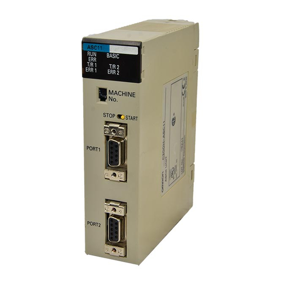
Section 2-1 Nomenclature and Functions Nomenclature and Functions 2-1-1 Names of Parts • Front Panel C200H-ASC11 C200H-ASC21 Indicators Unit No. switch START/STOP switch Communications Communications port 1: RS-232C port 1: RS-232C Terminating resistance switch 2-wire/4-wire switch Communications Communications port 2: RS-422/485... - Page 29 Nomenclature and Functions Section 2-1 • Back Panel C200H-ASC31 (Same for all models.) Cover Indicators Battery connector Unit No. switch Battery User memory Terminal port (port 3): default switch RS-232C START/STOP switch Communications Backplane port 1: RS-232C connector Communications port 2: RS-232C Note The above diagram shows the Unit with the cov- er removed.
- Page 30 1 (C200H-ASC31 only) Note If a PROGRAM MEMORY ERROR (BASIC program memory error) is gener- ated, all error indicators (ERR, ERR 1, ERR 2, ERR T) will flash. (Refer to 9-2 Troubleshooting for details.) C200H-ASC11 C200H-ASC21 C200H-ASC31 ASC11 ASC21...
- Page 31 Section 2-1 Nomenclature and Functions Unit No. Switch Set the unit number to between 0 and F. If the same number is set for other Special I/O Units, an I/O Unit Overflow error (fatal) will occur, and the system will not operate. CPU Unit Unit No.
-
Page 32: Installation
Section 2-2 Installation Installation 2-2-1 Installation Method 1,2,3... 1. Attach the hooks on the upper section of the ASCII Unit onto the Back- plane. 2. Insert the ASCII Unit connector into the Backplane connector. Hook Backplane Lock lever Note When removing the ASCII Unit, lift it out while pressing down on the lock lever with a screwdriver, as shown in the following illustration. - Page 33 Section 2-2 Installation Unit Dimensions when Mounted Dimensions ASC11 BASIC T/R 1 T/R 2 ERR 1 ERR 2 Cable connector Backplane connector 100.5 180 to 200 Mounting Positions and Number of Units CPU Unit Total No. of Units Mounting on CPU Rack, restrictions Expansion I/O Racks, and...
- Page 34 External devices are connected to the RS-232C or RS-422A/485 port. For interface code/timing, refer to SECTION 4 Data Exchange with General-pur- pose External Devices. RS-232C Connections Using the enclosed connector, connect all pins to match the external device (C200H-ASC11/21/31) interface. C200H-ASC11/21 C200H-ASC31 Symbol...
- Page 35 Section 2-2 Installation RS-422A/485 Using the enclosed connector, connect the pins to match the external device Connections interface. (C200H-ASC21 Only) Symbol Name Direction Send data A (–) Output Send data B (+) Output Not used Not used Not used Receive data A (–) Input Not used Receive data B (+)
- Page 36 2. CTS-RTS and DSR-DTR are not cross-connected, so if flow control is re- quired, use Xon/Xoff flow control. 2-2-3 General-purpose Peripheral Device Connections Bar Code Reader Connected with RS-232C Connecting an OMRON V500 Bar Code Reader C200H-ASC11/ASC21/ASC31 V520-RH21-6 ASCII Unit Bar Code Reader...
- Page 37 ASCII Unit end, but not both ends. 2. Make sure to set the 2/4-wire switch on the C200H-ASC21 Unit to 4 wires. Digital Operator Connected with RS-485 (2-wire) Connecting an OMRON ES100X Digital Operator C200H-ASC21 ASCII Unit 9-pin D-sub (female)
- Page 38 Section 2-2 Installation Note 1. Make sure that the shield is grounded at either the Digital Operator end or the ASCII Unit end, but not both ends. 2. Make sure to set the 2/4-wire switch on the C200H-ASC21 Unit to 2 wires.
-
Page 39: Ir/Cio And Dm Area Allocations
SECTION 3 IR/CIO and DM Area Allocations This section describes the methods used to allocate words to the ASCII Unit in the IR/CIO and DM Areas and the applications of the bits and words in these areas. IR/CIO Area Allocations ........3-1-1 Overview. -
Page 40: Ir/Cio Area Allocations
Section 3-1 IR/CIO Area Allocations IR/CIO Area Allocations 3-1-1 Overview Each ASCII Unit is allocated 10 words in the Special I/O Unit Areas of the CPU Unit’s IR or CIO Area. The words that are allocated depend on the Unit No. - Page 41 Section 3-1 IR/CIO Area Allocations Data Exchange for the CS1 Series CPU Unit ASCII Unit CIO Area Unit 0 CIO 2000 5 words Unit 0 CIO 2004 CIO 2005 5 words CIO 2009 CIO 2010 Data automatically exchanged during I/O Unit 1 refresh CIO 2019...
- Page 42 Section 3-1 IR/CIO Area Allocations Outputs The following words are output from the CPU Unit to the ASCII Unit. 15 14 13 12 11 10 Not used Write Bit (PC Read Request) Read Bit (PC Write Request) Not used PC Interrupt Bit Sync Time Set Bit Error Code Read Bit Output Data (from CPU Unit to ASCII Unit)
- Page 43 Section 3-1 IR/CIO Area Allocations Word Name Function Not used Write Bit 1: Establishes the execution conditions for When this bit is turned ON by the user pro- PC READ (Data transferred from CPU gram in the CPU Unit, data is transferred Unit to ASCII Unit according to the spec- according to the PC READ command at the ified First Transfer Word and Number of...
- Page 44 Section 3-1 IR/CIO Area Allocations Word Name Function n + 3 00 to No. of Trans- Number of words transferred when ASCII Data is written via the MOV instruction from fer Words Unit PC READ/PC WRITE command is the user program in the CPU Unit. If the executed (1 to 255).
- Page 45 Section 3-1 IR/CIO Area Allocations Input The following words are input from the ASCII Unit to the CPU Unit. 15 14 13 12 11 10 n + 5 ASCII Busy Flag PC Interrupt Subroutine Completed Flag IOWR Request Flag System BASIC Error Flag Not used IORD Request Flag Terminal Port Error Flag...
- Page 46 Section 3-1 IR/CIO Area Allocations Word Name Function n + 5 ASCII Busy 1: The ASCII Unit is exchanging data with When this flag is ON, the next transfer with Flag the CPU Unit. the ASCII Unit should not be executed in the user program in the CPU Unit.
- Page 47 Section 3-1 IR/CIO Area Allocations Word Name Function n + 6 00 to Input Data The data (16 bit) transferred from the The ASCII Unit’s PC PUT command writes ASCII Unit to the CPU Unit by a PC PUT data to the IR/CIO words allocated to the command at the ASCII Unit.
-
Page 48: Dm Area Allocations
Section 3-2 DM Area Allocations DM Area Allocations 3-2-1 Overview Each ASCII Unit is also allocated 100 words as shared memory from the CPU Unit’s Data Memory Area. The unit number determines which 100 words are allocated. The shared memory (100 words) in the ASCII Unit is divided into two regions as follows: •... - Page 49 Section 3-2 DM Area Allocations CS1-series PCs Unit No. Words Unit No. Words Unit No. Words D20000 to D20099 D20600 to D20699 D21000 to D21099 D20100 to D20199 D20700 to D20799 D21100 to D21199 D20200 to D20299 D20800 to D20899 D21200 to D21299 D20300 to D20399 D20900 to D20999...
- Page 50 Section 3-2 DM Area Allocations Note Setting the IORD/IOWR Areas within the following ranges. • Set the first word in the IORD Area, and the first word in the IOWR Area. • The IORD Area and IOWR Area can be set in any order and the first part of the allocated DM words can be left unused by either area.
- Page 51 Section 3-2 DM Area Allocations Shared Name Function Settings (hex) ASCII Unit’s memory address default address (hex) m + 2 00 to Port #1 baud Sets the baud rate for port #1. 00: 9,600 rate 01: 300 02: 600 03: 1,200 04: 2,400 05: 4,800 06: 9,600...
- Page 52 Section 3-2 DM Area Allocations Shared Name Function Settings (hex) ASCII Unit’s memory address default address (hex) m + 9 00 to Not used 10 to 99 m + 10 00 to IORD Area and IOWR Area (set first words at address 6 and 7) m + 99 Note 1.
-
Page 53: Data Exchange With General-Purpose External Devices
SECTION 4 Data Exchange with General-purpose External Devices This section describes the ASCII Unit commands in conjunction with transmission control signals for opening and closing communications ports and for sending and receiving data between the ASCII Unit and external devices. Overview . -
Page 54: Overview
Section 4-1 Overview Overview The following operations are covered in this section. Operation Command/function Opening a communications port OPEN command Sending data PRINT command (The LPRINT command executes device: LPRT.) Receiving CR terminator INPUT command data (The LINE INPUT command receives everything in one character variable). Specified character INPUT$ function length... -
Page 55: Open Command Specifications
Section 4-2 Opening a Communications Port 4-2-2 OPEN Command Specifications The following details are specified in the OPEN command. Item Settings Detail Device symbol (periph- SCRN, LPRT, • Use of the transmission/receive buffer. eral device name) EKPRT, NKPRT, • Control of the transmission control signals. KYBD, COMU, TERM Baud rate... -
Page 56: Control/Monitor Commands For Transmission Control Signals
Section 4-2 Opening a Communications Port 4-2-3 Control/Monitor Commands for Transmission Control Signals When control of the transmission control signals is not specified in the OPEN command (i.e., when they are set to OFF), they can be controlled and moni- tored using the following commands. -
Page 57: Sending Data
Section 4-3 Sending Data Note The differences between LPRT, EKPRT and NKPRT are shown in the follow- ing table. Device symbol External device Details LPRT When not outputting Chinese- No conversion from Shift JIS code to JIS code. derived characters (Kanji) NKPRT When outputting Chinese-derived Shift JIS code is converted to JIS code and... -
Page 58: Dma Data Transmission
Sending Data 4-3-2 DMA Data Transmission It is possible to transmit data using DMA (Direct Memory Access) depending on the model of ASCII Unit and the communications port used. Model C200H-ASC11 C200H-ASC21 C200H-ASC31 Port Port #1 Port #2 Port #1 Port #2... - Page 59 Section 4-3 Sending Data For OPEN Command with If CTS is ON, data will be transmitted. If CTS is OFF, data will not be transmit- CTS_ON, DSR_OFF ted and the Unit will wait for CTS to turn ON; the BASIC indicator will flash slowly.
- Page 60 Section 4-3 Sending Data Output Status by Device Symbol in the OPEN Command Code Meaning Communications port 1 Communications port 2 (port 1 for ASC31) TERM/SCRN LPRT/ COMU TERM SCRN LPRT/ COMU NKPRT/ NKPRT/ EKPRT EKPRT Space Output Output Output Output Not sup- Output Output...
-
Page 61: Receiving Data
Section 4-4 Receiving Data Receiving Data Data is received using the INPUT# command or the INPUT$ (<numeral expression>[,#<port expression>])) function. 4-4-1 INPUT# Command Use the INPUT# command to store data received from the receive buffer in variables using the CR code as a terminator. This allows reception of CR- delimited communications responses and input data from the keyboard. -
Page 62: Input$ Function
Section 4-4 Receiving Data • Use CTS_ON with the OPEN command and monitor the CTS signal for RTS/CTS flow control. • Use XN_ON with the OPEN command and perform Xon/Xoff flow con- trol. 3. When an ON COM interrupt is used, the baud rate of all ports will be as follows: Port 1 + port 2 ≤... -
Page 63: Closing A Communications Port
CLOSE command is executed, the data remaining in the receive buffer is cleared. All communications ports are also closed by the END, CLEAR, and NEW commands. They are not closed by the STOP command. 4-5-1 Transmission Control Signals Model C200H-ASC11 C200H-ASC21 C200H-ASC31 Port Port #1 Port #2 Port #1... - Page 64 Section 4-5 Closing a Communications Port RTS Signal Device symbol Transmission Executing Ports opened Receiving data Sending data Ports closed (peripheral control signal by OPEN# with INPUT# with PRINT# device name) operation command command or command setting INPUT$ function Port #1: TERM, RTS_ON ON to OFF OFF to ON...
- Page 65 Section 4-5 Closing a Communications Port DTR Signal Device symbol Executing RUN Ports opened by Receiving data Sending data Ports closed (peripheral OPEN# with INPUT# with PRINT# device name) command command or command INPUT$ function Port #1: TERM and COMU (Port #3 for ASC31) Port #2: COMU...
- Page 66 Section 4-5 Closing a Communications Port Timing Charts Device Symbol: TERM Port #1/Port #3 (ASC31): TERM Command Command Mode Mode Open Receive data Send data Close RTS_ON ON RTS-OFF ON CTS_ON No check No check No check Check No check No check (during send) CTS_OFF...
- Page 67 Section 4-5 Closing a Communications Port Port #2: COMU or Port #1: COMU for ASC31 Command Command Mode Mode Open Receive data Send data Close RTS_ON ON RTS_OFF Status depends on DTR command CTS_ON No check No check No check Check No check No check...
- Page 68 Section 4-5 Closing a Communications Port Port #2: KYBD Command Command Mode Mode Open Receive data Send data Close None RTS_ON RTS_OFF None Status depends on DTR command CTS_ON No check No check No check No check No check CTS_OFF No check No check No check...
-
Page 69: Communications Errors
Section 4-6 Communications Errors Port #2: SCRN or LPRT Command Command Mode Mode Open Receive data Send data Close None RTS_ON RTS_OFF None Status depends on DTR command CTS_ON No check No check Check No check No check (during send) CTS_OFF No check No check No check... - Page 70 Section 4-6 Communications Errors The ERR function can be used to determine the type of error that occurred. Since communications errors can be detected from the BASIC program, retry processing is easily performed from the BASIC program. ON ERROR GOTO *EINT Main program *EINT Error processing...
-
Page 71: Processing
SECTION 5 Processing This section provides examples of processing character strings, bits, receive buffers, looping, and interrupts. Processing Character Strings ........Processing Bits . -
Page 72: Processing Character Strings
Section 5-1 Processing Character Strings Processing Character Strings Process Programming Retrieving n characters from beginning of B$ = MID$(A$, 1, n) or B$ = LEFT$(A$, n) Retrieving n characters from character B$ = MID$(A$, m, n) number m Retrieving n characters from end of A$ B$ = RIGHT$(A$, n) Searching for character string from char- B = INSTR(m, A$, character_string) -
Page 73: Time Processing
Section 5-4 Time Processing Time Processing Process Program Storing a time in T$ (HH:MM:SS) T$ = TIME$ Storing hours in H$ (HH) H$ = LEFT$(TIME$, 2) or H$ = MID$(TIME$, 1, 2) Storing minutes and seconds in MS$ (MM:SS) MS$ = MID$(TIME$, 4, 5) Executing Using TIME$ interrupt, interrupt 100 ON TIME$ "**:**:00"... -
Page 74: Interrupt Functions
Interrupt Functions Section 5-5 Interrupt Functions Interrupt Details Program Enable/disable/ stop commands (See note 2.) Communi- The interrupt subroutine is executed when data is ON COM n GOSUB COM n cations received in the receive buffer. All data received is n: 1 or 2 (ON/OFF/STOP) interrupts... - Page 75 Section 5-5 Interrupt Functions Note 1. When an interrupt is generated upon receiving a specified number of char- acters or data up to a specified character, all data is received in the receive buffer. If the necessary number of characters is retrieved by the INPUT$ function, it is possible to use first-in/first-out (FIFO) processing to move that group of characters to the front of the receive buffer.
- Page 76 Section 5-5 Interrupt Functions Application Example ON COM 1 GOSUB 1000 COM 1 ON Communications interrupt enabled Interrupt subroutine 1000 RETURN The ON COM command is often used in conjunction with the INPUT$ function as shown below. (STX% = &H02, ETX% = &H03, Receive data = 0<LOC(2)<255) Example 1 ON COM 2 GOSUB 500...
-
Page 77: Loop Processing
Section 5-6 Loop Processing Loop Processing Process Programming Specified number of repetitions: 10 FOR A = 1 TO 3 If no response is received within 3 s of trans- 20 PRINT #2, C$ mission of the command (C$), the command is 30 WAIT "3.0", 50 40 A$ = INPUT$(1, #2): GOTO 1000 resent. -
Page 78: Data Exchange With The Cpu Unit
SECTION 6 Data Exchange with the CPU Unit This section describes procedures for exchanging data between the ASCII Unit and the CPU Unit, the transfer sequence, instruction/command timing, and the use of various interrupts. Overview of Data Exchanges ........6-1-1 Data Exchange Methods . -
Page 79: Overview Of Data Exchanges
Section 6-1 Overview of Data Exchanges Overview of Data Exchanges 6-1-1 Data Exchange Methods The ASCII Unit can exchange data with the CPU Unit in the following five ways. 1,2,3... 1. The CPU Unit designates its own read/write area in memory. If a PC READ/WRITE command is then specified from the CPU Unit, the ASCII Unit uses the PC READ/WRITE command to access the memory area in- dicated by the CPU Unit. - Page 80 Section 6-1 Overview of Data Exchanges 3. The CPU Unit and the ASCII Unit both access their own allocated words in memory. (The ASCII Unit accesses its own data in 16-bit units via the PC PUT/GET command.) The words allocated in the CPU Unit and memory words in the ASCII Unit are exchanged during the I/O refresh period.
-
Page 81: Sending Interrupts
Section 6-1 Overview of Data Exchanges 5. The ASCII Unit sets an IOWR Request Flag for the CPU Unit. When an IOWR (#FD00) instruction is executed, the CPU Unit writes data. Alter- nately, the ASCII Unit sets an IORD Request Flag for the CPU Unit. When an IORD (#FD00) instruction is executed, the CPU Unit reads data (sup- ported only by the C200HX/HG/HE and CS1-series PCs). - Page 82 Section 6-1 Overview of Data Exchanges 2. An interrupt is sent at the execution of the IOWR (#CC00) instruction. The IOWR (#CC00) instruction in the CPU Unit’s user program sends an inter- rupt, the interrupt number is sent to the ASCII Unit, and the program branches to the line number specified in the ON PC command.
-
Page 83: Selecting The Data Exchange Method
Section 6-2 Selecting the Data Exchange Method Selecting the Data Exchange Method CPU Unit ASCII Unit Data exchange Data Read/write data is CPU Unit and ASCII method number IOWR (#00@@) PC EGET read/write in not affected by I/O Asyn- Unit asynchronously 4., 5. -
Page 84: Details Of The Data Exchange Methods
Section 6-3 Details of the Data Exchange Methods Comparison Chart of Data The differences between the data exchange methods are shown in the table Exchange Methods below. Data ex- CPU Unit ASCII Unit Acces- Access Transfer ASCII Max. no. of transfer words change instructions commands... - Page 85 Section 6-3 Details of the Data Exchange Methods PC READ When the ASCII Unit receives an ON Write Bit from the CPU Unit, it reads the memory words specified in the allocated IR/CIO words, and stores the con- tents in the specified variable. 1,2,3...
- Page 86 Section 6-3 Details of the Data Exchange Methods PC WRITE When the ASCII Unit receives an ON Read Bit from the CPU Unit, it writes the contents of the specified variable to the I/O memory area specified in the allo- cated I/O.
-
Page 87: Data Exchange Method No. 2
Section 6-3 Details of the Data Exchange Methods 6-3-2 Data Exchange Method No. 2 The ASCII Unit independently reads/writes the CPU Unit memory during the I/ O refresh period. PC READ@ The ASCII Unit reads the CPU Unit memory as specified in the PC READ@ command. -
Page 88: Data Exchange Method No. 3
Section 6-3 Details of the Data Exchange Methods The following example is for a C200HX/HG/HE PC. CPU Unit ASCII Unit PC WRITE "@D, 200, 3, S3H4"; B (1) None 2. Via PC WRITE command DM 0200 B (1) 0201 B (2) 255 words max. -
Page 89: Data Exchange Method No. 7
Section 6-3 Details of the Data Exchange Methods PC GET The ASCII Unit converts the allocated word IR/CIO n bits 0 to 15 from hexa- decimal data to decimal data, and stores them in the first variable. It also con- verts the word IR/CIO n + 1 bits 0 to 15 from hexadecimal to decimal data and stores them in the second variable. - Page 90 Section 6-3 Details of the Data Exchange Methods Note 1. The PC EGET/EPUT commands can synchronize with the PC as they are executed by interrupts from the PC. PC interrupts are possible via IOWR instruction (control code #CC00) and allocated IR/CIO area words (word IR/CIO n bit 04 and word IR/CIO n + 2 bits 00 to 07).
- Page 91 Section 6-3 Details of the Data Exchange Methods 2. The IORD instruction is structured as shown below for the CS1-series PCs. The number of read words must be specified as a hexadecimal value. IORD (222) #0000 0004 0000 #00040000 Unit No. D00300 No.
- Page 92 Section 6-3 Details of the Data Exchange Methods 2. The IOWR instruction is structured as shown below for the CS1-series PCs. The number of write words must be specified as a hexadecimal value. IOWR (223) #FD00 D00300 0003 0000 #00030000 Unit No.
- Page 93 Section 6-3 Details of the Data Exchange Methods The following example is for a C200HX/HG/HE PC. CPU Unit ASCII Unit 10500 n + 5 bit 00 (See note 2) PC QWRITE "@D , 300, 3, 1H4, 1H4, 1H4"; 10514 IORD B (1), B (2), B (3) ASCII #FD00...
- Page 94 Section 6-3 Details of the Data Exchange Methods 6-3-6 Data Exchange Method No. 6 After the CPU Unit has written to the ASCII Unit’s shared memory area, it sends an interrupt to the ASCII Unit, and during the interrupt subroutine, the ASCII Unit reads from the shared memory.
- Page 95 Section 6-3 Details of the Data Exchange Methods 6-3-7 Data Exchange Method No. 7 The CPU Unit sends an interrupt to the ASCII Unit, and the ASCII Unit writes data to the shared memory. After the completion of the interrupt subroutine, the CPU Unit reads data from the shared memory.
-
Page 96: Data Exchange Time Charts
Section 6-4 Data Exchange Time Charts Data Exchange Time Charts 6-4-1 PC READ/PC WRITE Timing After a trigger is sent from the CPU, data is transferred at the next I/O refresh period. After receiving a PC WRITE or PC READ command, the ASCII Unit puts the BASIC program on standby until the data transfer is complete. -
Page 97: Pc Put/Pc Get Timing
Section 6-4 Data Exchange Time Charts 6-4-3 PC PUT/PC GET Timing Data is written during the I/O refresh period immediately after the execution of the PC PUT command. The ASCII Unit BASIC program continues execution. Data is read at the I/O refresh immediately after the execution of the PC GET command. -
Page 98: Iowr (#Fd00)/Iord (#Fd00) And Pc Qread/Pc Qwrite Timing
Section 6-4 Data Exchange Time Charts 6-4-6 IOWR (#FD00)/IORD (#FD00) and PC QREAD/PC QWRITE Timing Data transfer occurs as soon as a trigger arrives from the ASCII Unit and the IOWR (#FD00)/IORD (#FD00) command is executed. The ASCII Unit is on standby from the execution of the PC QREAD/PC QWRITE command until the execution of the IOWR (#FD00)/IORD (#FD00) command. -
Page 99: Combined Iowr (#Cc00), Iord (#00
Section 6-4 Data Exchange Time Charts 6-4-8 Combined IOWR (#CC00), IORD (#00 ) , ON PC GOSUB, and PC EPUT Timing The IOWR (#CC00) instruction sends an interrupt to the ASCII Unit. The inter- rupt subroutine is executed immediately andwrites to the shared memory using the PC EPUT command. - Page 100 Section 6-4 Data Exchange Time Charts Using IOWR Interrupt: The CPU Unit indicates an interrupt number to the ASCII Unit by using the Control Code: #CC00 IOWR (#CC00) instruction, and sends an interrupt. The ASCII Unit executes (C200NX/HG/HE and the interrupt subroutine which matches the interrupt number in an ON PC CS-1seried PCs only) command.
- Page 101 Section 6-4 Data Exchange Time Charts Interrupt by PC Interrupt Bit CPU Unit ASCII Unit Execution condition ON for 1 cycle ON PC a GOSUB 1000 n + 5 bit PC interrupt enabled condition PC Interrupt n bit 04 PC Fail Flag Interrupt Bit n + 5...
- Page 102 Section 6-4 Data Exchange Time Charts IOWR (#CC00) Interrupt: C200HX/HG/HE or CS1-series PCs Only CPU Unit ASCII Unit Execution condition ON for 1 cycle ASCII Busy Flag ON PC a GOSUB 1000 IOWR #CC00 #0001 PC Interrupt Fail Flag Interrupt permission 25506 1000 Equals Flag...
- Page 103 Section 6-4 Data Exchange Time Charts Timing Charts Interrupt Execution for PC Interrupt Bit 1., 2. MOV or OUT instruction DIFU instruction CPU Unit Interrupt Enable Flag Completion Interrupt PC Interrupt processing subroutine Number completion Interrupt ASCII Unit subroutine ON PC RETURN GOSUB + PC ON...
-
Page 104: Iowr/Iord Instruction Specifications
Section 6-5 IOWR/IORD Instruction Specifications Interrupt Failure (Same for PC Interrupt Bit Interrupts and IOWR (#CC00) Interrupts) 1., 2. MOV or OUT instruction CPU Unit Interrupt Enable Flag PC Interrupt Number Interrupt Fail ASCII Unit 4. ON PC GOSUB PC Interrupt Subroutine Completed Flag The Interrupt Fail Flag turns ON at the... - Page 105 Section 6-5 IOWR/IORD Instruction Specifications Writing to the ASCII Unit’s Variables Value Details Combination (4-digit hex.) Allocated IR/CIO area words IR/CIO n + 8 and Must be used in combination #FD00 IR/CIO n + 9 are transferred to the ASCII Unit's with the ASCII Unit's PC variable.
- Page 106 Section 6-5 IOWR/IORD Instruction Specifications CS1-series PCs Unit No. of the ASCII Unit (0 to F) D+1: D: Rightmost 4 digits D+1 : Leftmost 4 digits No. of Transfer Words (0001 to 0080 Hex from CIO n + 8) from CPU Unit to ASCII Unit Item Detail Operand...
- Page 107 Section 6-5 IOWR/IORD Instruction Specifications Data Item Detail C200HX/HG/HE Operand IR Area 1 IR 000 to IR 235 SR Area 1 SR 236 to SR 255 SR Area 2 SR 256 to SR 299 IR Area 2 IR 300 to IR 511 HR Area HR 00 to HR 99 AR Area...
- Page 108 Section 6-5 IOWR/IORD Instruction Specifications C200HX/HG/HE 12 11 No. of transfer words (001 to 090, limited by DM setting m +6/m +7) from the CPU Unit to the ASCII Unit Unit No. of the ASCII Unit (0 to F) CS1-series PCs Unit No.
- Page 109 Section 6-5 IOWR/IORD Instruction Specifications Interrupts to the ASCII Unit Value (4-digit Details Combination hex.) Sends an interrupt from the CPU Unit to the Must be used in combination #CC00 ASCII Unit. with the ASCII Unit's ON PC (Interrupt Number) command. S: Interrupt Number (corresponds to the ASCII Unit's ON PC (Interrupt Number) command).
- Page 110 Section 6-5 IOWR/IORD Instruction Specifications Clearing Errors in the ASCII Unit Value (4-digit Details hex.) #EC00 The current error status is cleared and the current errors are registered in the error history table as old errors. S: Always #0000 C200HX/HG/HE 12 11 Always 001 Unit No.
-
Page 111: Iord Instruction (Special I/O Unit Read)
Section 6-5 IOWR/IORD Instruction Specifications Value (see note) Less Than Flag (LE) (25507) Overflow Flag (OF) (25404) Underflow Flag (UF) (25405) Negative Flag (N) (25402) Note SR Area addresses for the C200HX/HG/HE, C200H, and C200HS are given in parentheses. 6-5-2 IORD Instruction (SPECIAL I/O UNIT READ) IORD C: Control code... - Page 112 Section 6-5 IOWR/IORD Instruction Specifications CS1-series PCs Unit No. of the ASCII Unit (0 to F) S+1: S: Rightmost 4 digits No. of transfer words (0001 to 0080 Hex from CIO n+8) S+1 : Leftmost 4 digits from the ASCII Unit to the CPU Unit. D: First destination word in CPU Unit's I/O memory from CIO n+8 and CIO n+9.
- Page 113 Section 6-5 IOWR/IORD Instruction Specifications Item Detail Indirect DM/EM *D00000 to *D32767 addresses in BCD *E00000 to *E32767 *En_00000 to *En_32767 (n = 0 to C) Constants Data Registers Directly addressing Index Registers Indirect addressing ,IR0 to ,IR15 using Index –2048 to +2047 ,IR0 to ,IR15 Registers DR0 to 15, IR0 to IR15...
- Page 114 Section 6-5 IOWR/IORD Instruction Specifications Data Item Detail C200HX/HG/HE Operand IR Area 1 IR 000 to IR 235 SR Area 1 SR 236 to SR 252 SR Area 2 SR 256 to SR 299 IR Area 2 IR 300 to IR 511 HR Area HR 00 to HR 99 AR Area...
-
Page 115: Using The Iowr And Iord Instructions
Section 6-5 IOWR/IORD Instruction Specifications Flags Value (see note) Instruction • The number of transfer words C., S., and D. settings are Execution Error is not in BCD, or it is 0 words correct. Flag or is greater than 128 words (ER) (25503) •... - Page 116 IOWR/IORD Instruction Specifications Section 6-5 Note Only one IOWR/IORD instruction (control code #FD00) can be executed dur- ing a single cycle. Execution n+5 bit conditions IOWR ASCII Busy Flag 25506 Equals Flag (See note 1.) Note 1. The Equals Flag (SR 25506 for the C200HX/HG/HE) turns ON when pro- cessing to the ASCII Unit by IOWR/IORD instructions has finished normal- ly.
-
Page 117: Restrictions For Cs1-Series Pcs
Section 6-6 Restrictions for CS1-series PCs Restrictions for CS1-series PCs There are five methods that can be used to transfer data between the CPU Unit and an ASCII Unit. Refer to 6-2 Selecting the Data Exchange Method for details. When an ASCII Unit is used with a CS1-series PC, however, there are addressing restrictions for some of these methods, as shown in the following table. -
Page 118: Using The Sync Time Set Bit For Cs1-Series Pcs
Section 6-6 Restrictions for CS1-series PCs Method 2: PC READ@ or PC WRITE@ The addresses shown in the following table can be specified for PC READ@ or PC WRITE@. Area CS1 address Designation method (see note) Code First word address DM Area D00000 to D06655 0000 to 6655... - Page 119 Section 6-6 Restrictions for CS1-series PCs cuted to use the Sync Time Set Bit, i.e., it cannot be used in PROGRAM mode.) Always ON Flag XFER #0004 A351 H118 In the physical memory structure, words H118 to H121 in the CS1-series CPU Units correspond to words AR 18 to AR 21 in C200HX/HG/HE CPU Units.
-
Page 120: Editing Basic Programs
SECTION 7 Editing BASIC Programs This section describes the procedures for editing, saving, starting, and stopping BASIC programs. An overview of BASIC program configuration, language definitions, and the use of various BASIC commands, statements, and functions is provided as well. Programming Procedure . -
Page 121: Programming Procedure
ASCII Unit 3. Turn OFF the power to the CPU Unit, and connect the RS-232C port (COM 1 in this example) to communications port #1 for the C200H-ASC11/ ASC21 or the terminal port for the C200H-ASC31 using an RS-232C ca- ble. - Page 122 When the following message is displayed at the terminal, connection is completed. C200H-ASCII UNIT Version 1.0x 1998/04/17 (c)Copyright OMRON Corporation 1998 READY > Note The above message is displayed only when the Ctrl+X Keys are pressed for the first time after the CPU Unit power is turned ON. If the terminal is disconnected and then reconnected, only the prompt “>”...
- Page 123 Section 7-1 Programming Procedure • That the communications parameters are the same for the ASCII Unit and terminal (DM m + 2 or m + 4 contain the terminal communications parameters) • If the ERR indicator on the front panel of the ASCII Unit is lit, indicating there is an error in word n + 7 (bits 00 to 11: Error Code, bits 12 to 15: Error Type), correct the error, reset the CPU Unit power supply, and then press the Ctrl+X Keys.
- Page 124 Section 7-1 Programming Procedure 0 bytes I–CODE : 41 bytes Transferring the BASIC Perform the following steps to transfer a BASIC program to the ASCII Unit Program Using a Text after compiling it using a text editor: Editor 1,2,3... 1. Edit the program using a text editor such as the Note Pad, and save it in text format.
-
Page 125: Saving Basic Programs
Section 7-1 Programming Procedure 7-1-2 Saving BASIC Programs Writing the BASIC The BASIC programs in the user memory (RAM) area can be written to the Program to Flash ROM flash ROM in the ASCII Unit by entering the ROMSAVE command from the terminal. -
Page 126: Transferring Basic Programs Between Ascii Unit And Terminal
Section 7-1 Programming Procedure 7-1-3 Transferring BASIC Programs Between ASCII Unit and Terminal Transferring BASIC Programs to the Terminal Use the following procedure to send BASIC programs from the user memory (RAM) of the ASCII Unit to the terminal. Terminal: VT100 Mode (Windows: Hyperterminal) 1,2,3... -
Page 127: Character Variable Space Allocations
(RAM)-to-flash ROM Character Variable Space Allocations When executing the BASIC program in a C200H-ASC11/ASC21/ASC31 ASCII Unit, the method can be selected for allocating space for character vari- ables to user memory. The following two methods are available. Note For numeric variables, the size of the variable area is fixed based on the type, and is therefore allocated in user memory using the static (fixed) method out- lined below. - Page 128 Section 7-2 Character Variable Space Allocations • The maximum length specified for the character variable content using the OPTION LENGTH command cannot be exceeded. If the maximum is exceeded, the amount of data over the limit will not be stored in the string variable “truncated.”...
-
Page 129: Starting/Stopping The Basic Program
Section 7-3 Starting/Stopping the BASIC Program • Place the PWORD command at the beginning of a statement if it is used with an OPTION LENGTH command. Starting/Stopping the BASIC Program 7-3-1 Starting the Program Selecting the Program When transferring DM data allocated in the CPU Unit to the ASCII Unit at Number power up or start up, the start program number is specified in bits 00 to 07 of DM m in the DM Setup Area allocated to the Unit. -
Page 130: Program Configuration
Section 7-4 Program Configuration Program Configuration A BASIC program consists of commands, statements, and functions. Commands General statements BASIC Language Statements Device control statements Arithmetic functions Built-in functions Character string functions Special functions Functions User-defined BASIC functions functions Basic Statements designate and control the flow of programs and are gener- ally used in program lines within a program. - Page 131 Section 7-4 Program Configuration • All inputs up until the Enter Key is pressed are stored in the user memory as a single line, in the order of line numbers. Execution is carried out in the order of line numbers. Line numbers are also used as references for branching destinations such as GOSUB and GOTO, and arguments in LIST and DEL.
-
Page 132: Character Set
Section 7-4 Program Configuration 7-4-3 Character Set The BASIC character set comprises alphabetical characters, numeric charac- ters, and special characters. The alphabetic characters in BASIC are the uppercase and lowercase letters of the alphabet. The numeric characters in BASIC are the digits 0 through 9. The following special characters are recognized by BASIC: SP (space) ! ”... - Page 133 Section 7-4 Program Configuration Floating Point Constants These are positive or negative numbers that are expressed in exponential for- mat. E (single-precision) or D (double-precision) is entered after the mantissa, and then the exponent is entered. Example: For the value 12,300,000, the following equations apply. = 1.23 ×...
-
Page 134: Variables
Section 7-4 Program Configuration 7-4-5 Variables Variables are names used to represent values that are used in a BASIC pro- gram. The value of a variable may be assigned as the result of calculations or explicitly by the programmer with an assignment statement. If no value is assigned to a numeric variable, it is assumed to be zero. -
Page 135: Type Conversion
Section 7-4 Program Configuration array and the length of its name are dictated by the amount of available mem- ory. An array has one subscript for each dimension in the array. For example, T(4) would reference the fourth element in the one-dimensional array T. -
Page 136: Expressions
Section 7-4 Program Configuration a long integer within the range of –2147483648 to 2147483647, an over- flow error will occur. Example: LET A = NOT 12.34, –13 is assigned as A. 5. When a real number is converted into an integer, the value is rounded. Example: A = 12.3: “12”... - Page 137 Section 7-4 Program Configuration Relational Operators Relational operators compare two values. The output is “–1” (&HFFFF) if the two values are equal and “0” if they are not. Relational operator Example Operation A = B Equal < >, > < A <...
-
Page 138: List Of Basic Commands
Section 7-5 List of BASIC Commands List of BASIC Commands The following table lists all BASIC commands alphabetically and gives an out- line for each. See 7-6 BASIC Commands for further details on each com- mand. Square brackets ([ and ]) in the syntax column indicate items that can be omit- ted. - Page 139 Section 7-5 List of BASIC Commands Command Syntax Details Command Statement Function Page CLEAR CLEAR Initializes numeric and General character variables and closes all ports. CLNG CLNG (numeric expression) Converts a value to a Arithmetic long integer. operation CLOSE CLOSE [#port number] Closes a port.
- Page 140 Section 7-5 List of BASIC Commands Command Syntax Details Command Statement Function Page DSR (port number) Reads status of DR Special signal. DTR (port number) SET or Sets/resets ER signal. Device DTR (port number) RESET control EDIT EDIT [Line number] Edits one line of the Command program.
- Page 141 Section 7-5 List of BASIC Commands Command Syntax Details Command Statement Function Page HEX$ HEX$ (numeric expression) Changes the decimal Character value given by the string argument to a hexadecimal character string. IF <numeric expression> Selects an executable General THEN[statement{:statement} statement or destination or <line number>...
- Page 142 Section 7-5 List of BASIC Commands Command Syntax Details Command Statement Function Page LINE INPUT LINE INPUT[;] [#port Reads one line of data General number,] [“prompt”;] from the reception buffer character variable of a specified port into the character variable. LIST LIST [line number 1] [–line Displays the program.
- Page 143 Section 7-5 List of BASIC Commands Command Syntax Details Command Statement Function Page ON ERROR ON ERROR GOTO <line Branches to interrupt General GOTO LINE number> subroutine when error is NUMBER generated. ON ERROR GOTO <label> ON NUMERIC ON <numeric expression> Branches to specified line General EXPRESSION...
- Page 144 Section 7-5 List of BASIC Commands Command Syntax Details Command Statement Function Page PC EPUT PC EPUT #<shared memory Writes shared memory General address>, <write number of data of ASCII Unit itself. words>,“format{,format}”; <numeric expression> {<numeric expression>} PC GET PC GET variable name 1 Reads the output data General [,variable name 2]...
- Page 145 Section 7-5 List of BASIC Commands Command Syntax Details Command Statement Function Page PRINT [USING] PRINT [#port number] Outputs expression value General [USING print format;] to specified port (in the expression {[,]expression} specified format). PRINT [#port number] [USING print format;] expression {[;]expression} PRINT [#port number] [USING print format;]...
- Page 146 Section 7-5 List of BASIC Commands Command Syntax Details Command Statement Function Page SAVE SAVE #port number Reads the BASIC Command [communications conditions program in user memory character expression] area to terminal. SEARCH SEARCH (integer type array Searches an integer Special variable, numeric expression array for the specified...
- Page 147 Section 7-5 List of BASIC Commands Command Syntax Details Command Statement Function Page VAL (character expression) Converts a character Character string into a numeric string value. VARPTR VARPTR (variable name) Determines or returns the Special memory address where the variable is stored. WAIT WAIT “waiting time”[,line Sets the monitoring time...
- Page 148 Details of BASIC Commands Section Details of BASIC Commands This section explicitly defines the functions, commands and statements of the BASIC language and gives examples of their use. The conventions used to describe the syntax of the BASIC Language are: 1.
- Page 149 Details of BASIC Commands Section (<numerical expression>) Syntax: Description: Function. Calculates the absolute value of a numerical expression. Remarks: <numerical expression> may be any short or long integer, single-precision floating point or double- precision floating-point expression. The range of the input argument, and therefore the output is equivalent to the allowable range of a double precision floating point.
- Page 150 Details of BASIC Commands Section alarm on/off/stop Syntax: ALARM STOP Statement. Enables, disables or stops the time interrupt Description: enables the interrupt. When this statement is executed the interrupt is unmasked. Remarks: ON ALARM If an interrupt occurs, program execution branches to the defined routine for ALARM GOSUB...
- Page 151 Details of BASIC Commands Section asin Syntax: (<numerical expression>) ASIN Function. Calculates the arc sine of a numerical expression. Description: <numerical expression> may be any integer, single-precision floating point or double-precision Remarks: floating-point expression. The valid range of the input argument is [-1, 1]. The return type is single-precision floating point if the argument is of type integer or single- precision floating point.
- Page 152 Details of BASIC Commands Section bitoff/biton Syntax: <integer variable> , <bit position> BITOFF <integer variable> , <bit position> BITON Description: Statement. turns ON (1) or OFF (0) the specified bit of an integer variable. Remarks: <bit position> is an integer expression returning a value in the range: [0…31]. 1.
- Page 153 Details of BASIC Commands Section cdbl Syntax: (<numerical expression>) CDBL Function. Converts the <numerical expression> into a double-precision floating point. Description: <numerical expression> may be any integer, single-precision floating point or double-precision Remarks: floating-point expression. If the <numerical expression> is an integer or single-precision floating-point integer, then CDBL will convert it to a double-precision floating-point integer.
- Page 154 Details of BASIC Commands Section cint Syntax: (<numerical expression>) CINT Function. Converts the <numerical expression> into an integer. Description: <numerical expression> may be any integer, single-precision floating point or double-precision Remarks: floating point. the valid range of the input is the valid range of a short integer: [-32768...
- Page 155 Details of BASIC Commands Section close Syntax: [# <port expression>] CLOSE Statement. Closes a communications port.. Description: <port expression> is an expression returning an integer in the range: [1… 3]. It is also possible in Remarks: this command to omit the # preceding the port expression. On closing a port, the data remaining in the output buffer of the communications port is sent, the data in the input buffer of the communications port is cleared.
- Page 156 Details of BASIC Commands Section cont Syntax: CONT Command. Resumes execution of the BASIC program after , after execution of Description: CTRL STEP statements, after encountering a breakpoint or after the occurrence of an error. STOP Remarks: Execution of the BASIC program resumes at the point after the break occurred. If the program has been changed or if the break occurs during data transfer with an external device then the BASIC program cannot be resumed.
- Page 157 Details of BASIC Commands Section Syntax: (<port expression>) Function. Reads the line of the specified communications port. Description: <port expression> is an expression returning an integer in the range: [1… 3]. Remarks: returns -1 if the line of the specified port is active and 0 if the line is not active.
- Page 158 Details of BASIC Commands Section Syntax: [= <numerical expression>] System variable. Returns the current day of the week or sets the day of the week. Description: <numerical expression> is an integer expression representing the day of the week. The days of the Remarks: week are represented in the following way: Day code...
- Page 159 Details of BASIC Commands Section def int/lng/sng/dbl/str Syntax: ) <letter> [- <letter>] {, <letter> [- <letter>]} Statement. Defines the type of variables beginning with the specified letters.. Description: The variables can be declared to be of type short integer ( ), long integer (LNG), single- Remarks: precision floating point (...
- Page 160 Details of BASIC Commands Section Syntax: <variable> ( <array index> {, <array index>} ) {,<variable> ( <array index> {, <array index>} )} Description: Statement. Specifies the order of the array and the maximum value for the array variable subscripts. Allocates the necessary memory for the array. Remarks: The <variable>...
- Page 161 Details of BASIC Commands Section Syntax: (<port expression>) Function. Reads the status of the specified communications port. Description: <port expression> is an expression returning an integer in the range: [1…2]. Remarks: returns -1 if is active for the specified port and 0 if is not active.
- Page 162 Details of BASIC Commands Section edit Syntax: (<line number> | . ) EDIT Command. Edits the specified line(s) of the BASIC program. Description: Allows editing of the BASIC program. If only one line number is specified then the editor will be Remarks: in single-line edit mode.
- Page 163 Details of BASIC Commands Section Syntax: Statement. Terminates program execution and returns to the command mode. All currently open Description: ports are closed. Remarks: can be used anywhere in a BASIC program. Like the CLOSE statement, the data remaining in the output buffer of the communications port is sent and the data in the input buffer of the communications port is cleared.
- Page 164 Details of BASIC Commands Section Syntax: System Variable. Stores the line number executing at the time an error occurred. Description: is a read-only system variable; it cannot be assigned a value. Remarks: can be helpful in error processing when used with and the statement.
- Page 165 Details of BASIC Commands Section error Syntax: <error number> ERROR Statement. Simulates the occurrence of an error. Description: <error number> is any valid error number in the range: [1…255]. Remarks: If a system error or a BASIC program error number is used the relevant error code will be put in the IR n+7 word and, if applicable, the error message will be printed to the screen.
- Page 166 Details of BASIC Commands Section Syntax: (<string expression>[, <fcs type>]) Function. Calculates the frame checksum of a string expression. Description: is calculated by performing one of the following operations on all bytes in the string Remarks: expression. The type of calculation is selected by <fcs type>.
- Page 167 Details of BASIC Commands Section Syntax: (<numerical expression>) Function. Returns the integer part of the numerical expression specified as the argument. Description: <numerical expression> may be any integer, single-precision floating point or double-precision Remarks: floating point. The return type is the type of argument. 1.
- Page 168 Details of BASIC Commands Section for to step / next Syntax: <variable> = <numeric expression 1> <numeric expression 2> [ <numeric expression STEP 3>] (: | <end-of-line>) <program> <variable> {,<variable>} NEXT Description: Statement. Allows the program segment between the and the statement to be repeated a NEXT number of times.
- Page 169 Details of BASIC Commands Section gosub Syntax: (<line number> | <label>) … GOSUB RETURN Statement Branches unconditionally to and returns from the subroutine specified by the line Description: number or label. Remarks: <line number> is the first line number in the subroutine and may be any valid line number in the range: [0 …65535].
- Page 170 Details of BASIC Commands Section hex$ Syntax: $(<numerical expression>) Function Converts the numerical expression into a hexadecimal character string. Description: The numerical expression must be in the range: [-2147483648…2147483647]. Remarks: The resulting character string will be in the hexadecimal range: [0…FFFFFFFF]. Note: 1.
- Page 171 Details of BASIC Commands Section Syntax: <numerical expression> ( [(<statement> {: <statement>} | <line number> | <label>)] | THEN (<line number> | <label>)) [ [(<statement> {: <statement>} | <line number> | GOTO ELSE <label>)]] Statement. Controls the flow of a program based on the results of a numerical expression. This Description: statement differs from the @ statement in that it supports statements only on a single line.
- Page 172 Details of BASIC Commands Section input Syntax: [;] [# <port expression>,][<prompt> (; | ,)]<variable> {, <variable>} INPUT Statement. Accepts input to a specified variable or variables during program execution. Description: <port expression> is an expression returning an integer in the range: [1… 3]. If the <port Remarks: expression>...
- Page 173 Details of BASIC Commands Section input$ Syntax: $ (<numerical expression> [, #<port expression>]) INPUT Function Reads a string of characters from the specified port. Description: <numerical expression> is an integer expression indicating the number of input characters to be Remarks: accepted.
- Page 174 Details of BASIC Commands Section Syntax: (<numerical expression>) Function Returns the truncated integer part of a numerical expression. Description: <numerical expression> may be any integer, single-precision floating point or double-precision Remarks: floating point. The return type is integer. returns the largest integer value that is less than or equal to the argument. Note: 1.
- Page 175 Details of BASIC Commands Section intrr Syntax: INTRR System Variable. Stores a number indicating the source of the interrupt. Description: is a read-only system variable; it cannot be assigned a value. Remarks: INTRR The value of is set only in the interrupt routine, outside the interrupt routine is 0.
- Page 176 Details of BASIC Commands Section key on/off/stop Syntax: [<key expression>] ( STOP Statement. Enables, disables or stops the interrupt Description: <key expression> is an integer expression returning a value in the range : [0…9]. This number Remarks: refers to the number keys on the keyboard. For instance, in the above example the interrupt connected to the ‘5’...
- Page 177 Details of BASIC Commands Section Syntax: ] <variable> = <expression> Statement. Assigns a value of the <expression> on the right hand side of the statement to the Description: variable on the left-hand side of the expression. Remarks: The keyword is optional in the assignment statement. It is sufficient to use the “=” character for assignment.
- Page 178 Details of BASIC Commands Section list Syntax: [(<line number> | . )][-[ (<line number> | . )]] LIST Command. To list the program in the current memory area to screen. Description: <line number> is any valid BASIC program line number in the range: [1…65535]. Remarks: The combination of <line numbers>...
- Page 179 Details of BASIC Commands Section llist Syntax: [(<line number> | . )][-[ (<line number> | . )]] LLIST Command. To list the program in the current memory area to Description: LPRT <line number> is any valid BASIC program line number in the range: [1…65535]. Remarks: The combination of <line numbers>...
- Page 180 Details of BASIC Commands Section load Syntax: # <port expression> [,<“communication definition string expression”>] LOAD Command. Loads an ASCII program to the ASCII Unit. Description: <port expression> is an expression returning an integer in the range: [1… 3]. Remarks: See the statement for a description of the <communication definition string expression>.
- Page 181 Details of BASIC Commands Section lprint [# <port expression>][ “<print format>”;] <expression>{(,|;|<space>)<expression>} Syntax: LPRINT USING Statement. Outputs data or text to a communications port. The device will be the LPRT regardless Description: of the settings in the command. OPEN <port expression> is an expression returning an integer in the range: [1 or 2]. Remarks: <expression>...
- Page 182 Details of BASIC Commands Section If the port number is omitted then port #1 is assumed for the statement and port #2 is PRINT assumed for the statement. LPRINT If the specified port is not configured as an output device then a “CANNOT WRITE TO A READ-ONLY DEVICE”...
- Page 183 Details of BASIC Commands Section mid$ Syntax: $ (<string 1>, < numerical expression 1>[, < numerical expression 2>]) = <string 2> Statement Replaces a portion of one string expression with another string expression. Description: <string 1> is the string where the characters from <string 2> should be replaced. Remarks: <string 2>...
- Page 184 Details of BASIC Commands Section Syntax: Command. Clears the program and all variables in the current memory area. Description: This statement is used to clear a program area before beginning to write a new program. All ports Remarks: are closed, all variables are cleared and the current program is deleted. Programs that are protected with a statement cannot be erased with .
- Page 185 Details of BASIC Commands Section oct$ Syntax: $(<numerical expression>) Function Converts the numerical expression into an octal character string. Description: The numerical expression must be in the range: [-2147483648…2147483647]. Remarks: The resulting character string will be in the octal range: [0…7777777777]. Note: 1.
- Page 186 Details of BASIC Commands Section on alarm Syntax: <time expression> (<line number> | <label>) ON ALARM GOSUB Statement. An interrupt is generated after the specified time elapses. When the specified time has Description: elapsed after execution of , program execution branches to the interrupt subroutine at ON ALARM the specified line number.
- Page 187 Details of BASIC Commands Section on com Syntax: [<port expression>] (<line number> | <label>) [ , ( [= <code expression>] | ON COM GOSUB CODE = <byte expression>) | = <code expression> , ( [ = <code expression >] | BYTE HEAD TERM...
- Page 188 Details of BASIC Commands Section For more information on writing interrupts in BASIC, refer to the examples in ON COM ON PC 5.5 Interrupt Functions. Note: 1. The port must be opened for input. 2. Set the baud rate in the communications parameters as follows: Port #1 + port #2 38.4 bps >...
- Page 189 Details of BASIC Commands Section on <expression> Syntax: <numerical expression> ( ) (<line number> | <label>) {, (<line number> GOTO GOSUB |<label>)} Description: Statement. Branches to one of the specified subroutines depending on the value of a numerical expression. Remarks: The value of the <numerical expression>...
- Page 190 Details of BASIC Commands Section on key Syntax: [<key expression>] ( ) ( <line number> | <label>) ON KEY GOTO GOSUB Statement. An interrupt subroutine is executed when the specified key (0 to 9) is input from the Description: keyboard. (Valid only when a terminal is connected.) Remarks: <key expression>...
- Page 191 Details of BASIC Commands Section on pc Syntax: [<interrupt number>] (<line number> | <label>) ON PC GOSUB Statement. Executes the specified interrupt number’s interrupt subroutine in response to allocated Description: I/O interrupts or IOWR (#CC00) instruction interrupts from the PC (CPU Unit). Remarks: The <interrupt number>...
- Page 192 Details of BASIC Commands Section on time$ Syntax: $ = <time string expression> (<line number> | <label>) ON TIME GOSUB Statement. Defines an interrupt subroutine to handle time$ interrupts. Description: <time string expression> is an absolute time in the format “hh:mm:ss”. Where hh has a range Remarks: [00…23], mm has a range [00…59] and ss has a range [00…59].
- Page 193 Details of BASIC Commands Section on timer Syntax: <time expression> (<line number> | <label>) ON TIMER GOSUB Statement. Defines an interrupt subroutine to handle recurring timer interrupts. Description: When the specified time has elapsed after execution of , program execution branches to ON TIMER the specified interrupt subroutine.
- Page 194 Details of BASIC Commands Section open Syntax: # <port expression>, <“communication definition string expression”> OPEN Statement. Opens a communication port with the specified device, port communications Description: conditions, and transfer control signal specifications. Remarks: <port expression> is an expression returning an integer in the range: [1… 3]. If the port expression is omitted, port #1 is the default.
- Page 195 Details of BASIC Commands Section The <baud rate> can be set to 300, 600, 1200, 2400, 4800, 9600, 19200, or 38400. The default baud rate setting is 9600 bps. The <data length> can be set to 7 or 8. If omitted the default data length is 8 bits. The <parity>...
- Page 196 Details of BASIC Commands Section The following defaults will be used for the devices if the communications parameters and valid signals are not specified. Device name Baud rate Data format Valid signals DM Area settings 8-bit, no parity, 2 stop CS_OFF, RS_ON, TERM bits...
- Page 197 Details of BASIC Commands Section option length Syntax: <numerical expression> OPTION LENGTH Statement. Declares the maximum length for string variables and sets the static method for Description: allocation of memory to string variables. Remarks: <numerical expression> specifies the maximum length of the string variables. It has a valid range of [1…255].
- Page 198 Details of BASIC Commands Section pc eget Syntax: [<result> = ] #<common memory address> , <number>, “<pc format> {, <pc format>}”; PC EGET <variable> {, <variable>} Description: Statement. Reads data from the common memory area of the ASCII Unit. Remarks: <common memory address>...
- Page 199 Details of BASIC Commands Section pc eput Syntax: [<result> = ] #<common memory address> , <number>, “<pc format> {, <pc format>}”; PC EPUT <numerical expression> {, <numerical expression>} Description: Statement. Writes data to the common memory area of the ASCII Unit. Remarks: <common memory address>...
- Page 200 Details of BASIC Commands Section pc get Syntax: <variable> [,<variable>] PC GET Statement. Reads data from IR n bits 0 through 15 to the first variable and IR n+1 bits 0 through Description: 15 to the second variable. The data is converted from hexadecimal to decimal. Remarks: <variable>...
- Page 201 Details of BASIC Commands Section pc qread @ Syntax: [<result> =] “<data area>, <address>, <number>, <pc format> {, <pc format>}”; PC QREAD <variable> {, <variable>} Description: Statement. Reads data from the specified PC memory area by issuing an IOWR request to the PC. Remarks: <data area>...
- Page 202 Details of BASIC Commands Section <address> specifies the starting address of data transfer within the specified data area. The starting address must be consistent with the address range of the specified data area. If the address given lies outside the allowable range then a “FORMAT ERROR” (code B067) will result. <number>...
- Page 203 Details of BASIC Commands Section pc qwrite @ [<result> =] “<data area>, <address>, <number>, <pc format> {, <pc format>}”; Syntax: PC QWRITE <numerical expression> {, <numerical expression>} Statement. Writes data to the specified PC memory area by issuing an IORD request to the PC. Description: Remarks: <data area>...
- Page 204 Details of BASIC Commands Section <address> specifies the starting address of data transfer within the specified data area. The starting address must be consistent with the address range of the specified data area. If the address given lies outside the allowable range then a “FORMAT ERROR”...
- Page 205 Details of BASIC Commands Section pc read Syntax: [<result> = ] “<pc format> {, <pc format>}”; <variable> {, <variable>} PC READ Statement. When a request is received from the CPU Unit, the data is read from the Description: PC READ specified PC data area and stored in the specified variable with the specified PC format.
- Page 206 Details of BASIC Commands Section bit 8 bit 9 bit 10 bit 11 bit 12 bit 13 bit 14 bit 15 A Format m A n Treats the m words as ASCII data and stores the specified character(s) in the string variable. m : the number of words n : the specified byte(s) Byte(s) read...
- Page 207 Details of BASIC Commands Section Note: 1. If the amount of PC output data exceeds the size of variable, the excess output data will be ignored. 2. If the size of variable exceeds the amount of PC output data, the read operation will not be executed to the variable where the shortfall occurred.
- Page 208 Details of BASIC Commands Section pc read@ Syntax: [<result> = ] “<data area>, <address>, <number of words>, <pc format> {, <pc PC READ format>}” ; <variable> {, <variable>} Description: Statement. Allows the ASCII Unit to independently read data from the specified PC data area. The data area, starting address, and number of words are all specified at the ASCII Unit.
- Page 209 Details of BASIC Commands Section <address> specifies the starting address of data transfer within the specified data area. The starting address must be consistent with the address range of the specified data area. If the address given lies outside the allowable range then a “FORMAT ERROR” (code B067) will result. <number of words>...
- Page 210 Details of BASIC Commands Section pc write Syntax: [<result> = ] “<pc format> {, <pc format>}”; <numeric expression> {, <numeric PC WRITE expression>} Description: Statement. When a request is received from the CPU Unit, the variable data is written to PC WRITE the specified PC data area in the specified PC format.
- Page 211 Details of BASIC Commands Section bit 3 bit 4 bit 5 bit 6 bit 7 bit 8 bit 9 bit 10 bit 11 bit 12 bit 13 bit 14 bit 15 A Format m A n Converts a string variable with 2×m characters to ASCII data (2 characters for each word of data) and stores the data in the m words.
- Page 212 Details of BASIC Commands Section statement can return a <result>. This <result> indicates whether the PC WRITE PC WRITE statement was successful or not. If the <result> is 0 then the command was successfully carried out and the data is written successfully. If the <result> is -1 then the could not be carried PC WRITE out, perhaps because another data transfer was being performed.
- Page 213 Details of BASIC Commands Section pc write@ Syntax: [<result> = ] “<data area>, <address>, <number of words>, <pc format> PC WRITE {, <pc format>}” ; <numeric expression> {, <numeric expression>} Description: Statement. Allows the ASCII Unit to independently write data to the specified PC data area. The data area, starting address, and number of words are all specified at the ASCII Unit.
- Page 214 Details of BASIC Commands Section <address> specifies the starting address of data transfer within the specified data area. The starting address must be consistent with the address range of the specified data area. If the address given lies outside the allowable range then a “FORMAT ERROR” will result. <number of words>...
- Page 215 Details of BASIC Commands Section peek Syntax: (<address expression>) PEEK Function Returns the contents (converted from ASCII code to decimal) of a specified address. Description: <address expression> is address to be ed. Valid range: [&H0E000…&H3FFFF]. Remarks: PEEK The result is an integer value representing the character code of the byte at the specified address. The returned integer will be in the range [0…255].
- Page 216 Details of BASIC Commands Section pinf Syntax: | <program expression>)] PINF Command. Displays information about the specified BASIC program area. Description: <program expression> is an integer in the range: [1…4]. If the program expression is outside the Remarks: allowable range an “ILLEGAL FUNCTION CALL” error (code B005) will result. Alternatively information about all BASIC program areas can be displayed by specifying PINF If no argument is supplied to the...
- Page 217 Details of BASIC Commands Section pmem Syntax: PMEM Command. Turns write protection of the current BASIC program area ON or OFF. Description: statement write protects the current BASIC program area. If protection is set using Remarks: PMEM then it is not possible to change or delete the BASIC program in the current BASIC PMEM ON program area.
- Page 218 Details of BASIC Commands Section poke Syntax: <address expression> , <numerical expression> POKE Statement. Writes one byte to the specified address. Description: <address expression> is the memory location that will be d and is an expression returning an Remarks: POKE integer in the range : [&H0E000…&H3FFFFF].
- Page 219 Details of BASIC Commands Section Prefixes \ at the beginning of the numeric value. \ allocates space for one digit position. A combination of ** and \\. Separates the integer portion of a numeric value by a comma every three digits from the right of the integer part. ^^^^ When specified at the end of a numeric field it specifies that exponential form should be used.
- Page 220 Details of BASIC Commands Section pword Syntax: <string expression> PWORD Statement. Assigns a password to the BASIC program area. Description: <string expression> is any valid BASIC string with a maximum length of 32 characters. If the Remarks: name is longer than 32 characters it will be truncated. Passwords are case-sensitive. statement must be the first line of the BASIC program.
- Page 221 Details of BASIC Commands Section read Syntax: <variable> {, <variable>} READ Statement. Reads values from statements and assigns them to the specified variables. Description: DATA <variable> is any valid BASIC numeric or character variable name. Remarks: statements must always be used in conjunction with statements.
- Page 222 Details of BASIC Commands Section renum Syntax: [<new line number>][,[<old line number>][, <increment>]] RENUM Command. Renumbers program lines. Description: <new line number> is the first line number to be used in the new sequence. It can be any valid Remarks: line number in the range : [1…65535].
- Page 223 Details of BASIC Commands Section resume Syntax: [(<line number> | RESUME NEXT Statement. Resume program execution after an error handling operation. Description: <line number> is any valid line number in the BASIC program from which execution will resume. Remarks: The valid range is [0…65535]. If <line number>...
- Page 224 Details of BASIC Commands Section Syntax: [(<numerical expression>)] Function. Returns a random number between 0 and 1. Description: <numerical expression> has a valid range: [-2147483648…2147483647] Remarks: If the <numerical expression> is negative the first number in the random number sequence is returned.
- Page 225 Details of BASIC Commands Section romsave Syntax: ROMSAVE Command. Saves BASIC programs in RAM to FlashROM. Description: All four BASIC program areas are saved from RAM to FlashROM. Remarks: Refer to 7-1 Programming Procedures for precautions on saving data to FlashROM. The ASCII Busy Flag will turn ON while the command is executing (i.e., while data is ROMSAVE...
- Page 226 Details of BASIC Commands Section Syntax: #<port expression> ( RESET Statement. Sets or resets the line of the specified communications port. Description: <port expression> is an expression returning an integer in the range: [1…3]. Remarks: If accompanied with the command the line is made active, if the command is used RESET...
- Page 227 Details of BASIC Commands Section save Syntax: # <port expression> [,“TERM:[<communication definition string expression>]”] SAVE Command. Writes the BASIC program in the current program area to a communication port. Description: <port expression> is an expression returning an integer in the range: [1… 3]. Remarks: See the statement for a description of the <communication definition string expression>.
- Page 228 Details of BASIC Commands Section Syntax: (<numerical expression>) Function. Returns the sign of a numerical expression. Description: <numerical expression> may be any integer, single-precision floating point or double-precision Remarks: floating point. returns 1 if the numerical expression is positive and -1 if the numerical expression is negative.
- Page 229 Details of BASIC Commands Section Syntax: (<numerical expression>) Function. Outputs blanks in a statement Description: PRINT LPRINT <numerical expression> may be any integer expression with a valid range: [0…255]. Remarks: Non-integer expressions will be rounded. If the expression is negative, 0 will be assumed. This function is used to output blanks in a statement.
- Page 230 Details of BASIC Commands Section step Syntax: [<numerical expression>] STEP Command. Executes the specified number of lines of BASIC program. Description: <numerical expression> specifies the number of program lines to execute, it may be any valid Remarks: integer expression in the range [0…255]. If it is omitted a value of 1 is assumed. command resumes execution at the line number after the last executed line.
- Page 231 Details of BASIC Commands Section str$ Syntax: $ (<numerical expression>) Function. Converts a numerical expression into a character string representation. Description: <numerical expression> may be any integer, single-precision floating point or double-precision Remarks: floating point expression. If the expression is positive a space is prefixed to the character string representation. If the numerical expression is negative a minus sign (-) is prefixed to the character string representation.
- Page 232 Details of BASIC Commands Section Syntax: (<numerical expression>) Function. Moves the cursor to a specified position on the terminal display in a Description: PRINT LPRINT statement Remarks: <numerical expression> may be any integer expression with the valid range: [1…255]. Non- integer expressions will be rounded.
- Page 233 Details of BASIC Commands Section time$ on/off/stop Syntax: TIME STOP Statement. Enables, disables or stops the time$ interrupt defined by the $ statement. Description: ON TIME enables (unmasks) the time$ interrupt. When a time$ interrupt occurs, program execution will Remarks: be branched to the specified interrupt subroutine for interrupt processing.
- Page 234 Details of BASIC Commands Section trace Syntax: TRACE Command. Displays the contents of the trace buffer. Description: When the command is executed, the program’s line numbers are stored in the trace buffer Remarks: TRON M as the program is executed. The trace buffer can contain up to 255 line numbers. The trace buffer has a battery backup, so its contents are retained even if the power is turned OFF.
- Page 235 Details of BASIC Commands Section tron Syntax: TRON Command. Turns ON the line number trace. If the option is specified the line numbers will be Description: output to a trace buffer. Remarks: command activates a debugging tool that displays program line numbers in the order TRON they are executed by the BASIC interpreter and in the time required to change line numbers.
- Page 236 Details of BASIC Commands Section varptr Syntax: (<variable>) VARPTR Function. Returns the memory address of a variable argument. Description: <variable name> must represent a valid variable in the BASIC program that has already had a Remarks: value assigned to it. The address of the value field in the identifier table is returned.
- Page 237 Details of BASIC Commands Section wait Syntax: <wait string> [, <line number>] WAIT Statement. Specifies a time-out for the statement following the statement. Description: WAIT <wait string> specifies the waiting time, after which a time-out will occur. It has the format “ Remarks: [<mm>:]<ss>.<t>”...
- Page 238 Details of BASIC Commands Section watch Syntax: ) <variable name>] WATCH Command. Sets, deletes or lists watched variables in the BASIC debugger. This command can be Description: used to identify the values of watched variables when the program stopped. Remarks: <variable name>...
- Page 239 Details of BASIC Commands Section while / wend Syntax: <numerical expression> <program> WHILE WEND Statement. Conditionally repeats the series of statements enclosed between Description: WHILE WEND The results of <numerical expression> determines the termination of the loop. If the result of the Remarks: <numerical expression>...
-
Page 240: User-Defined Basic Functions
Section 7-7 User-defined BASIC Functions User-defined BASIC Functions User-defined BASIC functions are expressions created by the user in BASIC and saved as user-defined functions. Other BASIC functions can be called up and executed by their specified function name in the same way. Function names, input variables, and expressions are declared using BASIC’s DEF FN command. -
Page 241: Debugging
Section 7-8 Debugging Debugging 7-8-1 Overview The debugging function allows you to stop the program at a specified line by various methods so that the contents of variables can be monitored. It is also possible to determine the position of the current line number. Note The breakpoint function can be used to set a breakpoint in an interrupt sub- routine, but it is not possible to continue executing the interrupt subroutine after the breakpoint. - Page 242 Section 7-8 Debugging Meaning BRKPT sets and deletes breakpoints. When no line is specified, the current breakpoint settings are displayed. Example BRKPT SET 200: Sets breakpoint at line 200. BRKPT DEL 100: Deletes breakpoint at line 100. BRKPT: Displays the current breakpoint settings. BRKPT DEL ALL: Deletes all the current breakpoint settings.
- Page 243 Section 7-8 Debugging Note Set the variables using the WATCH command after the program has been compiled for the RUN command. 7-8-5 Trace Function (TRON and TRACE) When the TRON command is executed, the executed program lines are dis- played at the terminal in order of execution. This allows you to see execution for programming such as for FOR to NEXT repetitions, and IF GOTO and GOSUB subroutine branching.
-
Page 244: Data Exchange Application Programs
SECTION 8 Data Exchange Application Programs This section provides examples of data exchange applications. Asynchronous Processing ........High-speed Data Exchanges . -
Page 245: Asynchronous Processing
Section 8-1 Asynchronous Processing Asynchronous Processing Example 1 The monitoring system allows measurement data (PV) from a controller to be set whenever required in the shared memory of the ASCII Unit. The CPU Unit reads this data from the ASCII Unit’s shared memory as required to monitor it. CPU Unit ASCII Unit ASCII Unit... -
Page 246: High-Speed Data Exchanges
Section 8-2 High-speed Data Exchanges CPU Unit ASCII Unit Writes to shared memory using the PC EPUT command Reads from the (ASCII Unit No. 1). shared memory of ASCII Unit No. 1 IORD to DM 0000 to DM 0009 Unit No. 1, #1010 10 words DM0000... - Page 247 Section 8-2 High-speed Data Exchanges Examples 2 When the ASCII Unit operates as a special BASIC processing unit, a trigger is sent from the CPU Unit to the ASCII Unit, which after processing, sends a trig- ger back to the CPU Unit. The CPU Unit assigns arithmetic processing outside its capability to the ASCII Unit, enabling high-speed processing for both Units by sharing the workload.
-
Page 248: High-Volume Data Exchanges
Section 8-3 High-volume Data Exchanges High-volume Data Exchanges Example Large volumes of data can be transferred when high speed is not required by sending production directions as recipe data (settings/parameters) to various machines from the host computer. Host Link or Network CPU Unit ASCII Unit... -
Page 249: Bit Data Exchanges
Section 8-5 Bit Data Exchanges Example 2 Multiple external devices are connected via the RS-422/485 ports, and polling is used to send commands. The response data is stored in variable arrays and uploaded to the CPU Unit as required. CPU Unit ASCII Unit PC WRITE@ Variable array... -
Page 250: Clearing Error Messages
SECTION 9 Clearing Error Messages This section provides a list of error messages, probable causes and possible corrections. List of Error Messages ......... . Troubleshooting . -
Page 251: List Of Error Messages
Section 9-1 List of Error Messages List of Error Messages If an error (BASIC error) is generated during the execution of a BASIC com- mand, or a system error is generated, the error code is stored in bits 00 to 11, and the error type is stored in bits 12 to 15 of the IR/CIO area (words n + 7) in the CPU Unit. - Page 252 Section 9-1 List of Error Messages The various error types, codes, error messages and actions are as follows: BASIC Errors Error Error message Probable cause Corrective measures code B001 NEXT WITHOUT FOR FOR command is missing. Confirm the FOR..NEXT combination. B002 SYNTAX ERROR The program syntax is not correct.
- Page 253 Section 9-1 List of Error Messages Error Error message Probable cause Corrective measures code B023 FOR WITHOUT NEXT The NEXT command or the WHILE Check the FOR...NEXT or command is missing. WHILE...WEND combinations. B024 MISMATCH: WHILE/WEND The WEND or WHILE command is Add a WEND or WHILE command.
- Page 254 Section 9-1 List of Error Messages Error Error message Probable cause Corrective measures code 0050 BAD PORT NUMBER The port number is incorrect. Check the port number. 0051 CANNOT READ FROM Inputting to a write-only external device. Check the port and external device WRITE-ONLY DEVICE specifications.
- Page 255 Section 9-1 List of Error Messages Execution Errors Error Error message Probable cause Corrective measures code 0062 PROTECTED PROGRAM Program is protected from the NEW When creating a new program using command. the NEW command, delete the program name using the PNAME“ ” command. If PMEM ON has been specified, execute the NEW command after executing PMEM OFF.
- Page 256 Section 9-1 List of Error Messages PC Interface Errors Error Error message Probable cause Corrective measures code 0080 No message. The IOWR/IORD instruction is Check the operands for the IOWR/ incorrect. IORD instructions. 0081 No message. Incorrect number of transfer (read/ Set the IOWR/IORD (#00 write) words in the IOWR/IORD instruction to a maximum of 90 words...
-
Page 257: Troubleshooting
Section 9-2 Troubleshooting When an error is generated, the following commands are used to include an error processing program within a BASIC program. Situation Command Remarks To branch to an interrupt subroutine when ON ERROR GOTO command Include an error processing program in the an error has been generated. - Page 258 Section 9-2 Troubleshooting Error Probable cause Possible correction ERR (error) indicator is flashing. The battery connector is disconnected. Connect the battery connector (Battery error) properly. The battery voltage has dropped. Replace with new battery. All ERR indicators are flashing and The BASIC program memory is Change the DM setting so that the PROGRAM MEMORY ERROR...
- Page 259 Section 9-2 Troubleshooting Troubleshooting Flowchart CPU Unit power ON Not lit RUN indicator (green) ERR indicator (red) Flashing Not lit ERR indicator (red) Not lit The BASIC program Normal operation DM settings are in- memory of the ASCII correct (See note on the Battery voltage is low System error or Unit is damaged.
-
Page 260: Procedure For Dealing With Damage To The Program Memory
Section 9-2 Troubleshooting Note The following flowchart shows the BASIC indicator during normal operation. Normal operation Flashing Not lit BASIC indicator (green) BASIC program is stopped. Slow flashing Quick flashing BASIC program is being executed. Waiting for transfer of Waiting for INPUT command, or BASIC program. -
Page 261: Cpu Unit Error Indicators
Section 9-3 CPU Unit Error Indicators CPU Unit Error Indicators The CPU Unit of the C200H/HS, C200HX/HG/HE, or CS1-series PC monitors errors that occur in the ASCII Unit as described in this section. The errors are indicated for the ASCII Unit as a Special I/O Unit. 9-3-1 Special I/O Unit Error List Error... -
Page 262: Useful Flags And Control Bits
Section 9-3 CPU Unit Error Indicators 9-3-2 Useful Flags and Control Bits Special I/O Unit Error The PC error flags in the following tables will indicate the following errors. Flags • Duplicated unit numbers on Special I/O Units • Refreshing between the CPU Unit and Special I/O Unit didn’t proceed normally. -
Page 263: Reading And Clearing The Error Log
Section 9-4 Reading and Clearing the Error Log Bit address Function C200H/HS C200HX/HG/HE AR 0109 SR 28109 A50209 Restarts Unit 9. SR 28110 A50210 Restarts Unit A (10).* SR 28111 A50211 Restarts Unit B (11).* SR 28112 A50212 Restarts Unit C (12).* SR 28113 A50213 Restarts Unit D (13).* SR 28114... -
Page 264: Maintenance
Section 9-5 Maintenance 9-4-2 Reading the Error Log Table The Error Log Table is reflected in the Allocated I/O as shown below. There- fore, the table can be read from the CPU Unit via the Allocated I/O. • When an error is generated, the newest error code and error type is set to n + 7 words in the IR/CIO Area Allocations. -
Page 265: Replacing Batteries
Section 9-5 Maintenance 9-5-2 Replacing Batteries 1,2,3... 1. Turn OFF the power. (If the power is already OFF, turn ON the power for at least one minute and then turn it OFF again.) 2. Press down on the lock lever of the Backplane with a screwdriver, and re- move the ASCII Unit. -
Page 266: Operating Precautions
In the C200H-ASC02, an interrupt cannot be generated while a BASIC program command is being executed. This is possible, however, for the C200H-ASC11/ASC21/ASC31. Therefore, if an interrupt is generated while a command is being executed and the same command is included in the interrupt subroutine, there will be com- petition between the two commands and operations will not run smoothly (e.g., if an interrupt is generated... - Page 267 External Devices). Terminal Emulation Mode Selection If the same terminal used with the C200H-ASC02 is to be used with the C200H-ASC11/ASC21/ASC31 and it supports VT100 mode, use VT100 mode. If the terminal does not support VT100 mode, use FIT10 mode.
- Page 268 In the C200H-ASC02, the BASIC source program is executed as it is input. To improve the execution speed of the BASIC program in the C200H-ASC11/ASC21/ASC31, once a BASIC source program is input, it is compiled to an intermediate code (a simpler code that identifies the command contents) and then it is executed. There- fore, if the RUN command is executed using the C200H-ASC11/ASC21/ASC31, there is a delay while compil- ing is being performed before the actual program is executed.
- Page 269 Appendix A Operating Precautions Saving Programs Never turn OFF the power to the PC while writing the program to flash ROM using the ROMSAVE command (until the command prompt is displayed at the terminal). Doing so will damage the flash ROM and saving data may be no longer possible.
- Page 270 Appendix A Operating Precautions Baud Rate for PC Data Transfer A maximum of 127 words of data can be transmitted in one cycle. If executing PC READ/PC WRITE with data of a comparatively large size (such as 127 words) and the data is being received using a high baud rate (19.2 kbps or higher), the overlap of data being received and sent will extend the time required to complete the trans- mission and the cycle time at the PC will also be extended.
- Page 271 Appendix A Operating Precautions In the above example, the subroutine will be branched from the 1,000th line to the 100th line using the ON ERROR GOTO command if an error occurs. In this case, exit from the subroutine by changing the 110th line from RESUME 20 (to resume from the 20th line after error processing) to RESUME NEXT (to resume from the line following the line that caused an error.) ASCII Unit Operation when Program Memory is Damaged When program memory is damaged a PROGRAM MEMORY ERROR or a Special Unit error on the PC side...
-
Page 272: Comparison With C200H-Asc02
Appendix B Comparison with C200H-ASC02 The following table provides details of the differences between the C200H-ASC11/ASC21/ASC31 and the C200H-ASC02 ASCII Units. For an overview of the comparison, see 1-5 Comparison with Previous ASCII Units. Item C200H-ASC02 C200H-ASC11/21/31 Executing programs Executes the source... - Page 273 Appendix B Comparison with C200H-ASC02 Item C200H-ASC02 C200H-ASC11/21/31 Flags/Control Bits Software Restart Bit Read Bit and PC Interrupt Bit Uses the Write Bit. The Read Bit and the PC Interrupt Bit are different. ASCII Busy Flag Changes status when the Does not change when the PC interrupt is generated.
-
Page 274: Pc Format
Appendix C PC Format PC Format When the ASCII Unit reads from and writes to the I/O memory data of the CPU Unit or the shared memory of the ASCII Unit itself using the following commands, it recognizes the data format of the I/O memory or shared memory. - Page 275 Appendix C PC Format Name Format Meaning Example H (hexadecimal) When variables Data of m words is regarded as 2H3: format are numerals: hexadecimal data, and the data Data of 2 words is regarded as from the rightmost 1 to n digits hexadecimal, and the data from m = 1 to 255 of each word is stored in each...
- Page 276 Appendix C PC Format Name Format Meaning Example S (array SmXn m = 1 to 255 Data of m words is regarded as S2I2: variable) format data in the specified format Data of 2 words is regarded as Note: X is any of n = same as (BCD, hexadecimal, octal, or BCD data and data from each...
- Page 277 Appendix C PC Format Name Format Meaning Example Two ×m characters from the A (ASCII) format mAn m = 1 to 127 2A3: beginning of 1 character The first 4 characters in 1 n = 1 to 3 variable are converted into character variable is converted ASCII data (2 characters to ASCII data, and stored to the...
- Page 278 Appendix C PC Format H Type Format → J = &HB PC READ "H1"; J = 11 → J = &HAB PC READ "H2"; J = 171 Integer PC word data → J = &H9AB PC READ "H3"; J = 2475 variables →...
- Page 279 Appendix C PC Format A Type Format If the integer variable type does not match, an error will be generated. PC word data PC READ "2A1"; A$ → A$ = "RT" Character PC READ "2A2"; A$ → A$ = "QS" variables PC READ "2A3";...
- Page 280 Appendix C PC Format Examples of PC WRITE Format Conversions I Type Format PC word data PC WRITE "I1"; J PC WRITE "I2"; J Integer variables ← J = 1234 PC WRITE "I3"; J PC WRITE "I4"; J PC WRITE "I1"; A$ PC WRITE "I2";...
- Page 281 Appendix C PC Format H Type Format PC word data PC WRITE "H1"; J PC WRITE "H2"; J Integer variables ← J = −30293 = &H89AB PC WRITE "H3"; J PC WRITE "H4"; J PC WRITE "H1"; A$ PC WRITE "H2"; A$ Character variables ←...
- Page 282 Appendix C PC Format O Type Format PC word data PC WRITE "O1"; J PC WRITE "O2"; J Integer variables ← J = 668 = &1234 PC WRITE "O3"; J PC WRITE "O4"; J PC WRITE "O1"; A$ PC WRITE "O2"; A$ Character variables ←...
- Page 283 Appendix C PC Format A Type Format If the integer variable type does not match, an error will be generated. PC word data PC WRITE "2A1"; A$ Character variables ← A$ = "QRST" PC WRITE "2A2"; A$ Q: &H51 R: &H52 PC WRITE "2A3";...
-
Page 284: Formats For Storing Variables In Memory
Appendix D Formats for Storing Variables in Memory Variables are stored to memory in the following ways, depending on the variable type. • Short Integer Variables Address 1 bit 15 bits S: Sign (0: positive, 1: negative) D: Numeric value •... - Page 285 Appendix D Formats for Storing Variables in Memory • Array Variables For one-dimensional arrays A (0) • As an element of the array, each variable is stored in memory in order. A (1) A (2) A (n) For two-dimensional arrays B (0, 0) •...
- Page 286 Appendix D Formats for Storing Variables in Memory VARPTR (Variable Name) Function Assigns the memory address where the variable value is stored. Notation Example B& = VARPTR (A) Details • Assigns the memory address to the area where variable data specified for the variable name is stored. •...
- Page 287 Appendix D Formats for Storing Variables in Memory Integer array variable Character string array variable Leftmost memory Leftmost memory Address Address block address block address Rightmost memory Rightmost memory block address block address A$ (0) A$ (0) address A$ (2) A$ (2) address A$ (3) A$ (3) address...
-
Page 288: Command Execution Time Samples
Appendix E Command Execution Time Samples Assignments Assignment Execution time (ms) 0.19 A%=1 0.14 A=A + 1 0.41 A=A – 1 0.41 A=A*1 0.39 A=A/1 0.41 A=A\1 0.36 A=A MOD 2 0.35 A=A∧ 2 0.52 A%=NOT A% 0.20 A%=A% AND 1 0.28 A%=A% OR 1 0.28... - Page 289 Appendix E Command Execution Time Samples Statement Execution time (ms) PC WRITE “I4”; A (See note 1.) PC WRITE “5I4”; A,B,C,D,E (See note 1.) PC WRITE “10I4”; A,B,C,D,E,F,G,H,I,J (See note 1.) PC WRITE “63H4”; A$ (See note 1.) 20.7 PC READ “@D,0,1,I4” A (See note 1.) PC READ “@D,0,5,5I4”;...
- Page 290 Appendix E Command Execution Time Samples Function Execution time (ms) A$=STRING$(250,”A”) B$=FCS(A$,1) Horizontal parity C%=FIX(1.1) 0.26 D$=HEX$(1) INPUT$(100,#2) C%=INT(1.1) 0.25 D$=LEFT$(”ASCII”,2) 0.51 A%=LEN(”ASCII”) 0.17 A%=LOC(2) 0.22 A=LOG(5) D$=MID$(”ASCII”,1,1) 0.62 D$=OCT$(&051) 0.54 D$=RIGHT$(”ASCII”,2) A=SIN(0.5) 0.73 A=SQR(2) 0.66 D$=STR$(1) 0.64 A=TAN(3) 1.01 A%=VAL(”A”)
-
Page 291: Sample Programs
Appendix F Sample Programs 1) Transferring PC Data from the ASCII Unit Ladder Program Execution command No. of transfer words #0005 DM Area: 5 words ASCII Busy First transfer word Flag #0000 DM 0000 (PC READ) Write Bit 10001 Basic Program 100 PC WRITE “5I4”;... - Page 292 Appendix F Sample Programs 4) Transferring ASCII Unit Data from the ASCII Unit to the PC Ladder Program A ladder program is not required. Basic Program 100 PC WRITE “@D,10,3,3I4”; A,B,C The 3 variables A, B, and C (4-digit data) is converted to BCD data and transferred (written) to the correspond- ing 4 digits (16 bits) of 3 words in the CPU Unit, beginning with the first transfer word (DM 0010).
- Page 293 Appendix F Sample Programs ASCII Unit Processing as PC Coprocessor Ladder Program DM 1006 = 0010 DM 1007 = 0050 Execution command Inputting data to ASCII Unit 10500 2 words of data beginning with DM 0000 are transferred to the leading address @IOWR #0000 D0000...
- Page 294 Appendix G Wiring RS-232C or RS-422A/485 Cable Connectors Cable Processing (End See the diagrams for the lengths required in each step. connected to FG) 1. Cut the cable to the required length. 1,2,3... 2. Peel the sheath using a razor blade without damaging the shield weaving. 25 mm 3.
-
Page 295: Wiring Rs-232C Or Rs-422A/485 Cable Connectors
Appendix G Wiring RS-232C or RS-422A/485 Cable Connectors Soldering Solder as described next. 1. Place a heat-shrinking tube around each wire. 2. Presolder each wire and to its connector pin. 3. Solder each wire firmly in place. 1 mm Soldering iron Heat-shrinking tube (Internal diameter: 1.5, r=10) 4. -
Page 296: Reserved Words
Appendix H Reserved Words Reserved word RENUM INTRS ALARM HELP RESET INTRR RESTORE LEFT$ AUTO INPUT RESUME BASE RETURN BITOFF LENGTH ROMLOAD BITON MID$ BRKPT ROMSAVE ACOS MODEL CLEAR LINE ROMVERIFY OCT$ CLOSE LIST ASIN PEEK LLIST RIGHT$ LOAD SAVE CDBL CONT LPRINT... -
Page 297: Index
Index Numerics cable wiring cables 2-wire/4-wire switch processing (WIRE) soldering character constant definition character expressions arithmetic expressions character strings ASCII communications processing with Peripheral Devices character variables asynchronous data exchanges allocating space auto start (5A) clearing error messages and START/STOP switch clearing errors Automatic transfer setting with the IOWR instruction... - Page 298 Index applications expressions ASCII Unit to CPU Unit definition asynchronous processing external devices bit data exchanges connecting from CPU Unit through shared memory exchanging data high-speed high-volume F–H receiving data selecting data exchange method flags sending data ASCII Busy Flag timing charts BASIC RUN Flag to CPU Unit through shared memory...
- Page 299 Index IORD/IOWR Area transfer setting PC Interface errors IORD/IOWR Areas Peripheral Device general connections IOWR Area specifying with device symbol first word setting Peripheral Devices IOWR instruction ASCII communications with clearing errors in ASCII Unit sending interrupts personal computer writing ASCII Unit variables use as a terminal writing to shared memory Port #1 baud rate setting...
- Page 300 Index STEP command when sending data step function (STEP) TRON command SYSMAC BUS Slave Racks troubleshooting restrictions on troubleshooting BASIC programs system configuration troubleshooting error messages troubleshooting flowchart Terminal transferring BASIC programs unit number switch terminal (MACHINE No.) using personal computer as a terminal user memory Terminal emulation setting DM Area allocations...
-
Page 301: Revision History
Revision History A manual revision code appears as a suffix to the catalog number on the front cover of the manual. Cat. No. W306-E1-3 Revision code The following table outlines the changes made to the manual during each revision. Page numbers refer to the previous version.
Need help?
Do you have a question about the C200H-ASC11 and is the answer not in the manual?
Questions and answers