
Subscribe to Our Youtube Channel
Related Manuals for Denkovi DAEnetIP4


Summary of Contents for Denkovi DAEnetIP4
- Page 1 DAEnetIP4 User Manual 08 June 2018 DAEnetIP4 Web enabled IP Controller User Manual Date: 08 June 2018...
-
Page 2: Table Of Contents
Content Features ........................3 Application examples....................4 Technical parameters ....................11 Connectors and ports (interfaces) ................12 4.1. DAEnetIP4 ports ....................12 4.2. DAEnetIP4 ports, led-s and jacks description .............12 Installation ........................15 5.1. Connect......................15 5.2. Power supply requirements ................15 5.3. Network connection ....................17 5.4. -
Page 3: Features
08 June 2018 1. Features DAEnetIP4 is the next generation multifunctional Ethernet device (IP controller) for management and control. It could be used for industrial and home automation, access control, fire and security systems and embedding in other systems. It is suitable also for controlling relay boards, monitoring different analogue sensors via internet. -
Page 4: Application Examples
DAEnetIP4 User Manual 08 June 2018 2. Application examples Bellow are shown ideas how DAEnetIP4 could be used. The examples are only conceptual and an additional equipment is required in actual implementations: Electrical appliances remote control applications Figure 1. Controlling electrical appliances remotely DAEnetIP4 can be used to control electrical appliances with combination of mechanical relays, solid state relays, contactors and so on. - Page 5 Monitoring and logging applications Figure 2. Monitoring sensors DAEnetIP4 can be used with success into monitoring and logging systems. It has 8 x 10 bit Analog Inputs (10-bit resolution) which can be level-extended in order to monitor temperature, humidity, distance, light and so on.
- Page 6 DAEnetIP4 User Manual 08 June 2018 Standalone applications with sensors and electrical devices Figure 3. Controlling electrical devices depending on sensors values The controller supports mode in which the Analog/Digital Inputs (sensors) can control the Digital Outputs (electrical devices).
- Page 7 Figure 4. DAEnetIP4 used in application for counting customers in shops DAEnetIP4 provides 8 x 16 bit counters (from 0 up to 65535) which can be used to count various events - for example detect when a person enters in a shop through the door.
- Page 8 Web based thermo-regulator Figure 5. Web based thermo-regulator Every DAEnetIP4 Digital Output can be set to work in "Regulator" mode where it can be controlled just from an Analog Input. The controller can be adjusted to set different outputs upon the input level from single Analog Input (one input can be configured to control many outputs).
- Page 9 DAEnetIP4 supports mode of controlling the Digital Output from Digital Input (buttons, switches...), Analog Input (sensors for temperature, humidity, distance, light...), RTC (week schedule), Manual Control (browser, SNMP, HTTP/XML) at the same time.
- Page 10 One of the possible applications for DAEnetIP2 is to be integrated in irrigation systems. It features two different modes: o Start and stop irrigation based on particular time. As DAEnetIP4 has its own RTC (real time clock) and build in back-up power (for days) it can turn on and off the system up to 30 times per a single day - it has organized a week schedule based table inside.
-
Page 11: Technical Parameters
DAEnetIP4 User Manual 08 June 2018 3. Technical parameters Table 1. Technical parameters Parameter Value Size (L / W / H), mm 85 / 48 / 17 Power supply voltage, V DC 7.5 - 25 Current consumption, mA 40mA at 24V, 70mA at 12V, 90mA at 9V... -
Page 12: Connectors And Ports (Interfaces)
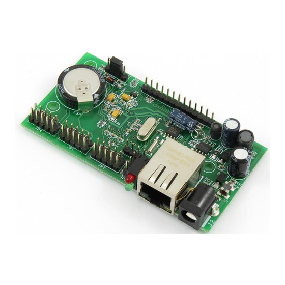
Bellow is shown a picture with the device connectors, ports and led indicators. Figure 8. Device overview 4.2. DAEnetIP4 ports, led-s and jacks description The first pin of every I/O port is marked with square footprint and all the rest pins are with circle footprints. - Page 13 DAEnetIP4 User Manual 08 June 2018 Table 3. Digital Inputs port JP2 Pin N Function Direction General Purpose Input #1 General Purpose Input #2 General Purpose Input #3 General Purpose Input #4 General Purpose Input #5 General Purpose Input #6...
- Page 14 DAEnetIP4 User Manual 08 June 2018 Table 7. PWM port JP6 Pin N Function Direction PWM1 PWM2 Figure 9. Power and status led The top led next to the RJ-45 indicates power presence (usually red). The bottom led is an indicator for status (usually green).
-
Page 15: Installation
40mA at 24V DC 70mA at 12V DC 90mA at 9V DC It is recommended the supply source for DAEnetIP4 to be with the following parameters: Supply voltage: 7.5V - 25V DC; Current: minimum 100mA;... - Page 16 DAEnetIP4 does not accept AC supply voltage. It is highly recommended to check the power supply source parameters before turning on the module.
-
Page 17: Network Connection
5.3. Network connection DAEnetIP4 supports AUTO-MDIX so either "crossover" or "straight-through" network cable can be used. Figure 14. UTP Cable Figure 15. Connecting DAEnetIP4 to a computer directly (recommended initial connection) Figure 16. Connecting DAEnetIP4 to a wireless router. -17-... -
Page 18: Communication Setup
DAEnetIP4 User Manual 08 June 2018 5.4. Communication setup DAEnetIP4 is shipped with the following default parameters: IP address: 192.168.1.100 Subnet mask: 255.255.255.0 Gateway: 192.168.1.1 Web password: admin Initially it is recommended to connect the module directly to the computer. - Page 19 DAEnetIP4 User Manual 08 June 2018 The next step is to enter into IPv4 properties. Figure 18. Enter in IPv4 properties section Set the IP address of your PC to be in the same network. Figure 19. Set the IP address...
- Page 20 DAEnetIP4 User Manual 08 June 2018 Finally, in order to access DAEnetIP4 just type in your browser 192.168.1.100 Figure 20. Open the device via browser If the network settings are O’K, the log-in page should appear: Figure 21. Login page...
-
Page 21: Reset And Default Settings
6. Reset and default settings 6.1. Table with default settings The DAEnetIP4 module is shipped with default (factory) settings shown in Table 8. The default settings can be reloaded, if necessary (see point 6.2). Table 8. Default settings Settings group... - Page 22 DAEnetIP4 User Manual 08 June 2018 SNMP Traps Enable Trap Trap sending Level Triggered Digital Inputs Description is the input Counter number: 1-8) Filter SNMP Traps Disabled SNMP Trap Value 0 (Closed) Analog Inputs Description is the input Trap Low Treshold...
-
Page 23: Steps For Loading Default Settings
Default position Figure 23. Loading the default settings When DAEnetIP4 is shipped from the factory, the jumper is placed on JP5 pins 2 and 3. 1. Turn off the power supply of the device; 2. Move the jumper to the DFT position (between pin 1 and 2);... -
Page 24: Web Access
7. Web access Figure 24. Web access To access the setup pages, run a web browser (Internet Explorer, Mozilla Firefox or similar), and enter the DAEnetIP4 IP address , for example: http://192.168.1.100 Figure 25. Open via browser Note: You will need to have JavaScript enabled in your browser. -
Page 25: Login
7.1. Login Figure 26. Login page Enter the password and click "Login" button. This will bring you to the DAEnetIP4 main configuration page which contains details for the current firmware version and build date and provides buttons and links to obtain further details. -
Page 26: Menu
DAEnetIP4 User Manual 08 June 2018 7.2. Menu The main menu consists of the following items, located in the left window frame: Figure 27. Navigation menu -26-... -
Page 27: General Settings
DAEnetIP4 User Manual 08 June 2018 7.3. General Settings Figure 28. General settings Device Name: The name of the module (max 15 symbols). Every module can have different name in your network so they can be distinguished; Password - the password used for logging into the web admin and XML/JSON operation (max. -
Page 28: Network Settings
Enabled, the Network page must be saved and DAEnetIP4 must be rebooted before obtaining an IP address; IP address: This is the IP address of the DAEnetIP4. It needs to be manually assigned only if DHCP is disabled. With DHCP enabled, this field displays the currently assigned address;... -
Page 29: Date And Time Settings
DAEnetIP4 User Manual 08 June 2018 7.5. Date and Time Settings Figure 30. Date/Time settings This page lets you configure the following parameters related with the real time clock built-in the module: Date (dd/mm/yyyy): Enter the current date here in specified format;... -
Page 30: Http, Xml And Json Access
DAEnetIP4 User Manual 08 June 2018 7.6. HTTP, XML and JSON Access Figure 31. HTTP & XML/JSON Access These settings let you configure the HTTP and XML/JSON access parameters of DAEnetIP4: HTTP Port: Port that the Web server listens for HTTP requests (default port is 80). - Page 31 DAEnetIP4 User Manual 08 June 2018 Save button: Once you have changed the settings as required, click this button. Note: When Encrypt XML Password mode is enabled, the Multiple XML Access option is not taken into account and, at any given moment, only one user can be logged-in.
-
Page 32: Snmp Agent
7.7. SNMP Agent Figure 32. SNMP settings These settings let you configure the SNMPv1 (Simple Network Management Protocol Version 1) access to the DAEnetIP4: Enable SNMP: This option enables or disables SNMP access to the DAEnetIP4; SNMP Port: UDP port number the SNMP agent receives requests on (default port is 161);... -
Page 33: Snmp Traps
7.8. SNMP Traps Figure 33. SNMP Trap settings DAEnetIP4 can send SNMPv1 traps upon input event (detected by a Digital and/or Analog Input) to a Trap server and its parameters can be set from this web page: Enable Trap: Enables or disables sending traps to the server;... -
Page 34: Digital Inputs
DAEnetIP4 User Manual 08 June 2018 7.9. Digital Inputs Figure 34. Digital Inputs settings Description: Digital Input identification string (max 7 chars); Counter: Every digital input works as a 16 bit counter as well. The counter is incremented at rising, falling, or both edges depending on the SNMP Trap Value. -
Page 35: Analog Inputs
DAEnetIP4 User Manual 08 June 2018 7.10. Analog Inputs Figure 35. Analog Inputs settings Description: Analog Input identification string (max 7 chars); Min - the value used for scaling where the analog input is with value 0 (minimum value: -9999.9, maximum value: 9999.9);... -
Page 36: Digital Outputs
DAEnetIP4 User Manual 08 June 2018 7.11. Digital Outputs Figure 36. Digital Output names Description: Output identification string (max 7 chars); This description will appear in XML/JSON files, as well as in the Monitoring & Control page. Working Mode: Determines how to work the Digital Output: o Regulator - in this mode the Output can be controlled only by Analog Input. - Page 37 DAEnetIP4 User Manual 08 June 2018 o Toggle(DI=0) - a falling edge (1 -> 0) of the Digital Input toggles the Relay state between On and Off; o Toggle(DI=1) - a rising edge (0 -> 1) of the Digital Input toggles the Relay state between On and Off;...
- Page 38 DAEnetIP4 User Manual 08 June 2018 Figure 38. Treshold 1 < Treshold 2 Disable Week Schedule: Enables/Disables globally the week schedule control for this output. This means the output may be in the schedule, but if this flag is enabled, then it won't be activated by the schedule;...
-
Page 39: Pwm Outputs
DAEnetIP4 User Manual 08 June 2018 7.12. PWM Outputs Figure 39. PWM settings Description: PWM output identification string (max 7 chars); Duty Cycle (0..100%): Determines the duty cycle of the PWM outputs. The PWM frequency is 40 KHz... -
Page 40: Monitoring And Control
DAEnetIP4 User Manual 08 June 2018 7.13. Monitoring and control Figure 40. Monitoring and control This page provides monitoring and control of the DAEnetIP4 I/O via AJAX requests (almost in real time). -40-... -
Page 41: Week Schedule
DAEnetIP4 User Manual 08 June 2018 7.14. Week Schedule Figure 41. Week schedule This page configures the Week Schedule table for switching Digital Outputs in High (ON) or Low (OFF) at specific times. You can add up to 30 time items to the list. -
Page 42: Logout
DAEnetIP4 User Manual 08 June 2018 7.15. Logout Figure 42. Log off 7.16. Reboot Figure 43. Reboot -42-... -
Page 43: Http/Xml/Json Access
This operation mode allows custom applications to control the DAEnetIP4 without using a Web-browser. The custom application acts as a HTTP client, sending HTTP GET requests to the DAEnetIP4. To receive the current state of the DAEnetIP4, the application requests the page current_state.xml , for example: http://192.168.1.100/current_state.xml... -
Page 44: Login (Non-Encrypted Password)
If there is no data traffic between the custom application and the DAEnetIP4 for time, specified by Session Timeout parameter, the session "times out" and a new login is required. -
Page 45: Getting The I/O Current State
08 June 2018 8.3. Getting the I/O current state After a login the custom application can obtain the DAEnetIP4 current state by a request to the page current_state.xml or current_state.json with or without login procedure (depending on the settings) : http://192.168.1.100/current_state.xml... - Page 46 DAEnetIP4 User Manual 08 June 2018 http://192.168.1.100/current_state.json The reply contains page in JSON format: -46-...
-
Page 47: Multiple Xml/Json Access
Password option is enabled. 8.5. Parameters After a login the custom application can also control the DAEnetIP4 by sending parameters (name/value pairs) with the HTTP request. Valid parameters and values are shown in the bellow table. Table 9. Valid HTTP parameters... -
Page 48: Snmp Access
DAEnetIP4 User Manual 08 June 2018 9. SNMP access DAEnetIP4 supports SNMPv2 protocol. Most of the parameters can be configured/read via snmp commands. Read-only community string is used for reading and Read-Write Community String is used for changing the parameters. - Page 49 DAEnetIP4 User Manual 08 June 2018 x.1.2.3.1.4.0 x.1.2.3.1.4.15 DigitalOutput read- Digital Output INTEGER AnalogPlusIn write <- Analog (0..8) putNo Input (+) Control (None- 0, AIn1-1, AIn2-2, ..., AIn8-8) x.1.2.3.1.5.0 x.1.2.3.1.5.15 DigitalOutput read- Digital Output INTEGER DigitalInputN write <- Digital Input (0..8)
- Page 50 DAEnetIP4 User Manual 08 June 2018 Inverse(DI=1)- x.1.2.3.1.13.0 x.1.2.3.1.13.15 DigitalOutput read- Digital Output INTEGER AnalogMinus write <- Analog (0..8) InputNo Input (-) Control (None- 0, AIn1-1, AIn2-2, ..., AIn8-8) x.1.2.3.1.16.0 x.1.2.3.1.16.15 DigitalOutput read- Digital Output INTEGER UseFilter write Use Filter (No-...
-
Page 51: Week Schedule
DAEnetIP4 User Manual 08 June 2018 Flag (Disabled-0, Enabled-1) x.1.2.2.1.6.0 x.1.2.2.1.6.7 AnalogInput read- Analog Input INTEGER { Value write ADC Value no(0),yes(1) x.1.2.2.1.7.0 x.1.2.2.1.7.7 AnalogInput read- Analog Input DISPLAYST write Min Value RING (SIZE (maxlen=7) (0..7)) x.1.2.2.1.8.0 x.1.2.2.1.8.7 AnalogInput read-... -
Page 52: Control
DAEnetIP4 User Manual 08 June 2018 Output16 - bit x.1.5.2.1.5.0 x.1.5.2.1.5.29 Hour read- Hour (hh:mm) DISPLAYST write RING x.1.5.2.1.6.0 x.1.5.2.1.6.29 WeekDays read- WeekDays INTEGER write Code (0..127) (0..127), Sunday - bit ..., Saturday - bit 9.5. Control Table 17. Control... -
Page 53: Security Considerations
DAEnetIP4 User Manual 08 June 2018 Security considerations DAEnetIP4 runs a special firmware and do not have a general-purpose operating system. There are no extraneous IP services found on general-purpose operating systems (e.g. fingerd, tcp_wrapper, etc.) that can possibly be exploited by an unauthorized agent. -
Page 54: I/O Ports
Maximum output voltage at low level is 0.4V DC; Minimum output voltage at high level is 2.4V DC; There is pull-down resistor of 4.7K connected to GND inside DAEnetIP4 for every JP1/JP3 output pin. The Digital Outputs ports are not protected and they are connected directly to the CPU! Over-current will damage the CPU! Figure 45. -
Page 55: Digital Inputs Port Jp2
High level (1) input voltage: From 1.63V DC up to 5.5V DC; Maximum input voltage on any JP2 input pin is 5.5V DC; There is pull-up resistor connected to 3.3V inside DAEnetIP4 for every JP2 input pin. -
Page 56: Analog Inputs Port Jp4
Analog Inputs Port JP4 Figure 48. DAEnetIP4 Analog Inputs port JP4 There is pull-down resistor of 68K connected to GND inside DAEnetIP4 for every JP4 input pin; Maximum input voltage on any JP4 input pin should not be more than 2.048V The Analog Inputs port is not protected and it is connected directly to the CPU! Over-voltage or inverse polarity voltage will damage the CPU. -
Page 57: Pwm Port Jp6
PWM Port JP6 Figure 50. DAEnetIP4 PWM port JP6 There is pull-down resistor of 10K connected to GND inside DAEnetIP4 for every JP6 input pin; The PWM port is not protected and it is connected directly to the CPU! -
Page 58: Pcb Mechanical Drawing
DAEnetIP4 User Manual 08 June 2018 PCB mechanical drawing Figure 51. PCB drawing (top view) -58-...
Need help?
Do you have a question about the DAEnetIP4 and is the answer not in the manual?
Questions and answers