
Subscribe to Our Youtube Channel
Related Manuals for Denkovi DAEnetIP4


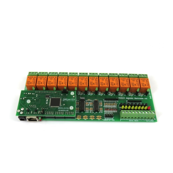
Summary of Contents for Denkovi DAEnetIP4
- Page 1 DAEnetIP4 SNMP 12 Channel I/O Relay Module User's Manual Date: 19 June 2018 Page 1...
-
Page 2: Table Of Contents
Content About this document................... 3 Overview ......................4 Relay Outputs ....................5 Digital Inputs (counters) ..................8 Analog Inputs ....................11 PWM Outputs ....................14 Installation ......................15 Loading the default (factory) settings ............... 21 Restart the module ................... 22 PCB dimensions .................. -
Page 3: About This Document
Internet/Ethernet 12 Channel Relay Board - I/O, SNMP, Web. This module consist of DAEnetIP4 controller and extension I/O relay board which is the main object of this document. For full description of the all DAEnetIP4 features, you can refer to DAEnetIP4 user's manual. Page 3... -
Page 4: Overview
8 x digital inputs port with schmitt trigger (0-12VDC or 0-24VDC). The inputs are combined with 16 bit cyclic counters as well; 8 x analog inputs (0-10VDC) 2 x PWM outputs (coming from DAEnetIP4) Led indicators for: relays, digital inputs, power on Sensor supply output ... -
Page 5: Relay Outputs
Current consumption 10 (28 VDC) 15 (120 VAC) Switching parameters 10 (250 VAC) Table 2. Mapping to DAEnetIP4 JP1/JP3 digital output port Digital output pin # (DAEnetIP4 JP1 and Relay # (from peripheral board) JP3) Digital Output #1 (JP1.1) Relay 1 Digital Output #2 (JP1.2) - Page 6 Example SNMP commands SNMP GET COMMANDS Get Relay 1 State snmpget -v1 -c read 192.168.1.100 .1.3.6.1.4.1.42505.1.2.3.1.11.0 DENKOVI-MIB::DigitalOutputState.0 = INTEGER: off(0) Get Relay 12 State snmpget -v1 -c read 192.168.1.100 .1.3.6.1.4.1.42505.1.2.3.1.11.11 DENKOVI-MIB::DigitalOutputState.11 = INTEGER: on(1) Get all relays states with single command snmpget -v1 -c read 192.168.1.100 .1.3.6.1.4.1.42505.1.3.2.0...
- Page 7 SNMP SET COMMANDS Set Relay 1 State OFF snmpget -v1 -c read 192.168.1.100 .1.3.6.1.4.1.42505.1.2.3.1.11.0 i 0 DENKOVI-MIB::DigitalOutputState.0 = INTEGER: off(0) Set Relay 12 State snmpget -v1 -c read 192.168.1.100 .1.3.6.1.4.1.42505.1.2.3.1.11.11 i 1 DENKOVI-MIB::DigitalOutputState.11 = INTEGER: on(1) Set all relays states with single command snmpget -v1 -c read 192.168.1.100 .1.3.6.1.4.1.42505.1.3.2.0 i 65535...
-
Page 8: Digital Inputs (Counters)
4. Digital Inputs (counters) Figure 5. Location of the digital inputs DAEnetIP4 IP controller (the core of the current module) supports 8 digital inputs every of which is combined with 16 bit cyclic counter. These inputs are extended with Schmitt triggers in this module so they are able to handle voltages from 0 up-to 30V DC. - Page 9 -v1 -c read 192.168.1.100 .1.3.6.1.4.1.42505.1.2.1.1.7.0 DENKOVI-MIB::DigitalInputState.0 = INTEGER: off(0) Get Counter1 Value snmpget -v1 -c read 192.168.1.100 .1.3.6.1.4.1.42505.1.2.1.1.7.0 DENKOVI-MIB:: DigitalInputCounter.0 = INTEGER: 12345 Get Din8 Value snmpget -v1 -c read 192.168.1.100 .1.3.6.1.4.1.42505.1.2.1.1.3.0 DENKOVI-MIB::DigitalInputState.0 = INTEGER: on(1) Get Counter8 Value snmpget -v1 -c read 192.168.1.100 .1.3.6.1.4.1.42505.1.2.1.1.7.7...
- Page 10 4.2. How to use the digital inputs Figure 7. How to use digital inputs Page 10...
-
Page 11: Analog Inputs
The input voltage range of 0-10V DC can be changed up-on request. The resistors used for building the module are +-5%. The ADC of the DAEnetIP4 also have some tolerance, so additional software calibration may be necessary. Figure 8. Location of the analog inputs port Figure 9. - Page 12 Against reverse Protection polarity Table 6. Mapping to DAEnetIP4 JP4 analog input port Analog input pin # (DAEnetIP4 JP4) Analog Input # (peripheral board) Analog Input #1 (JP4.1) Ain1 Analog Input #1 (JP4.2) Ain2 Analog Input #1 (JP4.3) Ain3 Analog Input #1 (JP4.4)
- Page 13 Figure 10. Monitoring and Control web page - Analog Inputs monitoring 5.1.2. Example SNMP commands Get Ain1 Level snmpget -v1 -c read 192.168.1.100 .1.3.6.1.4.1.42505.1.2.2.1.6.0 DENKOVI-MIB::AnalogInputValue.0 = INTEGER: 107 Get Ain8 Level snmpget -v1 -c read 192.168.1.100 .1.3.6.1.4.1.42505.1.2.2.1.6.7 DENKOVI-MIB::AnalogInputValue.7 = INTEGER: 555 Page 13...
-
Page 14: Pwm Outputs
6. PWM Outputs The PWM outputs are those from DAEnetIP4. For more information please refer to the DAEnetIP4 documentation: http://denkovi.com/Documents/DAEnetIP4/Current-Version/UserManual.pdf Figure 11. PWM outputs location Page 14... -
Page 15: Installation
400mA at 24V DC (and all relays are ON) 700mA at 12V DC (and all relays are ON) It is recommended the supply source for DAEnetIP4 12 Relay Module to be with the following parameters: Supply voltage: 7.5V - 25V DC;... - Page 16 DAEnetIP4 12 Relay Module does not accept AC supply voltage. It is highly recommended to check the power supply source parameters before turning on the module.
- Page 17 Figure 15. UTP Cable Figure 16. Connecting DAEnetIP4 12 Relay Module to a computer directly (recommended initial connection) Figure 17. Connecting DAEnetIP4 12 Relay Module to a wireless router. 7.4. Communication setup DAEnetIP4 is shipped with the following default parameters: ...
- Page 18 Initially it is recommended to connect the module directly to the computer. Next you have to change your PC’s IP address. You can Google how to change you computer IP settings or just visit this web page: http://www.howtochangeipaddress.com/changeip.php For Windows 7 OS for example you can do that in the following way: Navigate to Control Panel ->...
- Page 19 The next step is to enter into IPv4 properties. Figure 19. Enter in IPv4 properties section Set the IP address of your PC to be in the same network. Figure 20. Set the IP address Page 19...
- Page 20 Finally, in order to access DAEnetIP4 12 Relay Module just type in your browser 192.168.1.100 Figure 21. Open the device via browser If the network settings are O’K, the log-in page should appear: Figure 22. Login page DAEnetIP4 modules connected locally can be easily scanned and found...
-
Page 21: Loading The Default (Factory) Settings
When necessary, the factory (default settings) may be applied so the DAEnetIP4 parameters will be loaded back. Figure 24. System port JP5 When DAEnetIP4 is shipped from the factory, the jumper is placed on JP5 pins 2 and 3. Turn off the power supply of the device;... -
Page 22: Restart The Module
9. Restart the module The module may be restarted via one of the ways described bellow: Unplug the power supply, wait 10 seconds and plug it again; Move the jumper to Reset Position (Figure 24), wait 10 seconds and then get it back to it's old position. -
Page 23: Pcb Dimensions
PCB dimensions Page 23...
Need help?
Do you have a question about the DAEnetIP4 and is the answer not in the manual?
Questions and answers