
Related Manuals for Denkovi DAEnetIP4


Summary of Contents for Denkovi DAEnetIP4
- Page 1 DAEnetIP4 SNMP Five Channel Relay Module - User's Manual 08 Aug 2017 DAEnetIP4 SNMP Five Channel Relay Module User's Manual Date: 08 Aug 2017...
-
Page 2: Table Of Contents
DAEnetIP4 SNMP Five Channel Relay Module - User's Manual 08 Aug 2017 Content About this document................... 3 Overview ......................4 Relay Outputs ....................6 I/O Ports ......................9 Installation ......................10 Loading the default (factory) settings ............... 16 Restart the module ................... 17... -
Page 3: About This Document
DAEnetIP4 SNMP Five Channel Relay Module - User's Manual 08 Aug 2017 About this document This document describes only the specific features of the device Ethernet Five Relay Board with DAEnetIP4. This module consist of DAEnetIP4 controller and extension 5 channel relay board which is the main object of this document. -
Page 4: Overview
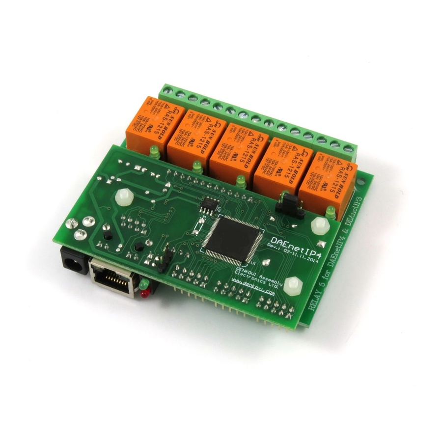
DAEnetIP4 SNMP Five Channel Relay Module - User's Manual 08 Aug 2017 2. Overview Figure 1. Module overview - PCB version Figure 2. Module overview - BOX version... - Page 5 8 x digital outputs (coming from DAEnetIP4), accessible in PCB version only; 8 x digital inputs (coming from DAEnetIP4) , accessible in PCB version only; 8 x analog inputs (coming from DAEnetIP4) , accessible in PCB version only;...
-
Page 6: Relay Outputs
DAEnetIP4 SNMP Five Channel Relay Module - User's Manual 08 Aug 2017 3. Relay Outputs The module provides 5 SPTD relays (NO, C, NC) and for every relay there is led indicator showing the relay state. When the led is ON, that means the relay is activated and when OFF, the relay is not activated. - Page 7 DAEnetIP4 SNMP Five Channel Relay Module - User's Manual 08 Aug 2017 3.1. How to control the relays 3.1.1. Web browser The relays states can be changed from the "Monitoring and Control" web page up on changing the dropdown combo-boxes (On/Off) in the section "Digital Outputs": Figure 5.
- Page 8 DAEnetIP4 SNMP Five Channel Relay Module - User's Manual 08 Aug 2017 SNMP SET COMMANDS Set Relay 1 State OFF snmpget -v1 -c read 192.168.1.100 .1.3.6.1.4.1.42505.1.2.3.1.11.8 i 0 DENKOVI-MIB::DigitalOutputState.8 = INTEGER: off(0) Set Relay 12 State snmpget -v1 -c read 192.168.1.100 .1.3.6.1.4.1.42505.1.2.3.1.11.12 i 1 DENKOVI-MIB::DigitalOutputState.12 = INTEGER: on(1)
-
Page 9: I/O Ports
08 Aug 2017 4. I/O Ports Some of the I/O ports can be accessed easily directly from DAEnetIP4 - 8 x Digital Outputs (JP1), 8 x Digital Inputs (JP2), 8 x Analog Inputs (JP4) and 2 x PWM outputs(JP6). For more information please refer to the DAEnetIP4 documentation: http://denkovi.com/Documents/DAEnetIP4/Current-Version/UserManual.pdf... -
Page 10: Installation
140mA at 24V DC (and all relays are ON) 210mA at 12V DC (and all relays are ON) It is recommended the supply source for DAEnetIP4 Five Relay Module to be with the following parameters: Supply voltage: 12V or 24V DC (depending on the selected model);... - Page 11 DAEnetIP4 Five Relay Module does not accept AC supply voltage. It is highly recommended to check the power supply source parameters before turning on the module.
- Page 12 DAEnetIP4 Five Relay Module supports AUTO-MDIX so either "crossover" or "straight-through" network cable can be used. Figure 12. UTP Cable Figure 13. Connecting DAEnetIP4 Five Relay Module to a computer directly (recommended initial connection) Figure 14. Connecting DAEnetIP4 Five Relay Module to a wireless router.
- Page 13 DAEnetIP4 SNMP Five Channel Relay Module - User's Manual 08 Aug 2017 DAEnetIP4 is shipped with the following default parameters: IP address: 192.168.1.100 Subnet mask: 255.255.255.0 Gateway: 192.168.1.1 Web password: admin Initially it is recommended to connect the module directly to the computer.
- Page 14 DAEnetIP4 SNMP Five Channel Relay Module - User's Manual 08 Aug 2017 The next step is to enter into IPv4 properties. Figure 16. Enter in IPv4 properties section Set the IP address of your PC to be in the same network.
- Page 15 DAEnetIP4 SNMP Five Channel Relay Module - User's Manual 08 Aug 2017 Finally, in order to access DAEnetIP4 Five Relay Module just type in your browser 192.168.1.100 Figure 18. Open the device via browser If the network settings are O’K, the log-in page should appear: Figure 19.
-
Page 16: Loading The Default (Factory) Settings
When necessary, the factory (default settings) may be applied so the DAEnetIP4 parameters will be loaded back. Figure 21. System port JP5 When DAEnetIP4 is shipped from the factory, the jumper is placed on JP5 pins 2 and 3. 1. Turn off the power supply of the device;... -
Page 17: Restart The Module
DAEnetIP4 SNMP Five Channel Relay Module - User's Manual 08 Aug 2017 7. Restart the module The module may be restarted via one of the ways described bellow: Unplug the power supply, wait 10 seconds and plug it again;...
Need help?
Do you have a question about the DAEnetIP4 and is the answer not in the manual?
Questions and answers