
Related Manuals for HP 3585A


Summary of Contents for HP 3585A
-
Page 1: Service Manual
SERVICE MANUAL SPECTRUM ANAL YZER 3585A VOLUME I HEWLETT General Information Installation Operation Overview PACKARD Performance Test Adjustments Circuit Descriptions Scans by ARTEK MEDIA Backdating =>... - Page 2 Model 3585A Table of Contents VOLUME TABLE OF CONTENTS Section VIII. FAULT ISOLATION REPLACEABLE PARTS SCHEMATICS VOLUME TABLE OF CONTENTS Section SERVICE Scans by ART EK MEDIA =>...
-
Page 3: Table Of Contents
2-14. Rack Mounting With Slides ... 2-5 4-31. Semi-Automatic Performance Tests ..4-35 2-15. Instrument Turn On ....2-6 2-16. HP-IB Connections and Interfacing ..2-9 4-32. HP-IB Address Switch Settings ..4-35 4-33. Semi-Automatic Performance 2-17. Cable Length Restrictions .... 2-9 2-18. - Page 4 5-45. Electrical Isolation Test..... 5-68 7-2 . .:l1-90MHz Filter Circuit..'" .. 7-1 5-46. Tracking Generator Adjustment ..5-69 7-3. Applicable Serial Numbers ... 7-1 5-47. HP-IB Adjustment....5-69 Affected Manual Areas ....7-1 7-4. 5-48. X-Y Plotter Adjustment.... 5-70 7-5.
-
Page 5: Section Page
4-1. Recommended Test Equipment.... .4-2 Group Cross Reference ....4-48 5-1. Adjustment Locations ..... 5-1 4-2. HP-IB Error Definitions ....4-32 5-2. Recommended Adjustment Equipment ..5-3 4-3. HP-IB Check Program Listing For The 9825A Calculator. - Page 6 5-30. Un symmetrical IF Display ....5-39 4-6. IM Distortion Response ....4-27 5-31. Symmetrical IF Display ....5-39 4-7. HP-IB Check Flowchart.... .4-33/4-34 5-32. LC Stage, 30kHz Amplitude Reference ..5-40 4-8. Frequency Accuracy Test....4-38 5-33. LC Stage, 1kHz Amplitude Adjustment..5-41 4-9.
- Page 7 7-4. Symmetry Adjustment..... 7-4 6-18. X-Y Plotter Block Diagram ... 6-47/6-48 6-19. Switching Power Supply Block ..6-51/6-52 7 -5. Reference Level Set-up ....7-5 6-20. 3585A Detailed Block Diagram ..6-53/6-54 viii Scans by ART EK MEDIA =>...
- Page 8 AND INSTRUCTIONS The cathode-ray tube (CRT) supplied in your Hewlett-Packard Instrument and replacement CRT's purchased from -hp- are warranted by the Hewlett-Packard Company against elec trical failure for a period of one year from the date of shipment from Colorado Springs.
- Page 9 SAFETY SYMBOLS General Definitions of Safety Symbols Used On Equipment or In Manuals. Instruction manual symbol: the product will be marked with this symbol when it is necessary for the user to refer to the instruction manual in order to protect against damage to the instrument. Indicates dangerous voltage (terminals fed from the interior by 1000 voltage exceeding...
- Page 10 HEWLETT PACKARD SAFETY SUMMARY The following general safety precautions must be observed during all phases of operation, service, and repair of this instrument. Failure to comply with these precautions or with specific warnings elsewhere in this manual violates safety standards of design, manufacture, and intended use of the instrument. Hewlett·Packard Company assumes no liability for the customer's failure to comply with these requirements.
-
Page 11: General Information
1 ·2. SPECIFICATIONS Operating specifications for the 3585A are listed in Table 1 - 1 . These specifications are the performance standards or limits against which the instrument is tested . Any changes in specifications due to manufacturing, design or traceability to the U . S . National Bureau of Standards are included in Table 1 - 1 of this manual. -
Page 12: Description
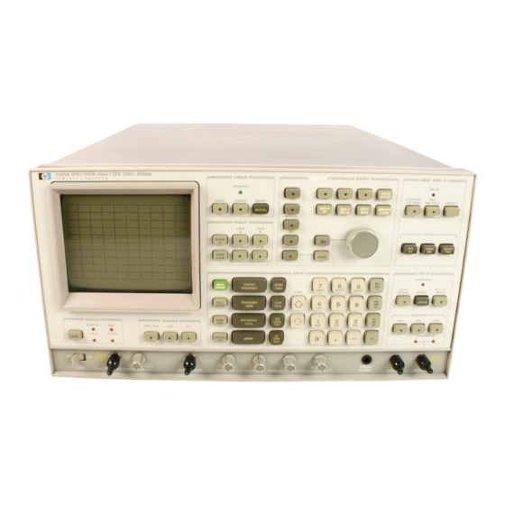
Manual Changes supplement and all pertinent Service Notes. 1 ·4. DESCRIPTION The 3585A is a 20 Hz to 40. 1 MHz, microcomputer controlled spectrum analyzer. It may be utilized for spectrum analysis or network analysis (amplitude only) applications. As a spec... -
Page 13: Options
CRT alphanumerics . A 50-character line of annotation or six 50-character lines of instructional messages can be displayed on the 3585A using the HP-lB. Finally, the keyboard may be con figured as a limited data input terminal, with each key having a unique, numeric code. -
Page 14: 1-7. Accessories Available
Model 3585A Figure 1-1. Accessories Supplied 1-7. ACCESSORIES AVAILABLE The following is a list of accessories available for use with the Model 3585A. Input Probes. 1120A 1: 1 active probe provides 100 kO shunted by 3 pf. 10021A 1: 1 passive probe for 50 or 1 MO shunted by 70 pf. -
Page 15: Recommended Test Equipment
Model 3585A 1 ·8. Recommended Test Equipment Equipment required to maintain the Model 3585A is listed in Table 1 -2. Other equipment may be substituted if it meets the requirements listed in the table. Table 1 · 1 . Specifications... - Page 16 General Information Model 3585A Table 1 · 1. Specifications (Cont'd) Displayed Range: Vertical Scale: 1 0 division CRT settable to 1 0 , 5, 2 and 1 dB/division relative to the Reference Level ( which is represented by the top graticu l e line)
- Page 17 Model 3585A General Information Table 1 - 1 . Specifications (Cont'd) INPUT: Signal Inputs: Terminated ( 501 7 50) i nput; > 26 dB return loss, DC coupled, BNC connec tor. Applied d c voltage must be ten times the RA N G E setti ng i n volts for fu l l specification compliance.
- Page 18 General Information Model 3585A Table 1 - 1 . Specifications (Cont'd) DYNAMIC RANGE: Spurious Responses: (which includes image, out of band and harmonic � distortion ) referred to a single signal whose ampl itude is ::;; RAN G E setting and whose frequency is ten times the Resolution Bandwidth .
- Page 19 Model 3585A General Information Table 1 · 1 . Specifications (Cont'd) DISPLAY: Trace: Two memories, A and B, each 1 00 1 data points horizontal ly by 1 0 2 4 data poi nts vertically are displayed on the C RT at a flicker free rate.
-
Page 21: Installation And Interfacing
Performance Tests, notify the nearest -hp- Sales and Service Office . If the shipping container is damaged or the cushioning material shows signs of stress , notify the carrier as well as the Hewlett -Packard Office . Keep the shipping materials for the carrier 's inspection . -
Page 22: Operating Environment
2· Operating Environment In order for the 3585A to meet the specifications listed in Table 1 - 1 , the operating environ ment must be within the following limits: Temperature ....ooe to + 55°e ( + 32°F to + 1 3 1 °F) .. -
Page 23: Storage And Shipping Environment
Because of its weight, the 3585A is not equipped with a tilt stand. It is recom mend that a Front Handle Kit (Option 907, -hp- Part No . 506 1 -0091 ) be installed for ease of handling the instrument on the bench. -
Page 24: Rack Mounting Without Slides
Install the Rack Flange Kit with or without handles according to the instructions in cluded in the kit: Rack Flange Kit (no handles) ..Option 908, -hp- Part Number 5061 -()()79 &... -
Page 25: Rack Mounting With Slides
Use extreme care when lifting it to avoid personal injury. f. Using two people, lift the 3585A to its position in the rack and mate the two sections of the slides together. Do not rest the full weight of the 3585A on the extended slides until you are sure the instrument rack will not overturn. -
Page 26: Instrument Turn On
OVEN REF OUT and EXT REF IN connectors. (For information con cerning the use of an external frequency reference, see the 3585A Operating Manual. ) c . Set the front-panel LINE switch t o the OFF position. -
Page 27: Front-Panel Functions Activated At Turn -On
3 . Verify that the front-panel SWEEPING light is flashing . If any of the above conditions is not met , turn the instrument off immediately and contact the nearest -hp- Sales and Service Office or a qualified service technician . COUPLED... -
Page 28: Turn-On Display
03 ") appears on the CRT screen, the instrument is either defective or in need of adjustment. Turn the instrument off and see the Fault Isolation information in Volume Two or the Preliminary Troubleshooting procedures in Volume Three. k . The 3585A's specifications are met after a 20-minute warmup at the ambient operating temperature. NOTE When the internal Oven Re ference is enabled (about ten minutes after turn on), the beeper will sound and the "LOCAL OSC. -
Page 29: Hp-Ib Connections And Interfacing
2·1 6. Hp·IB CONNECTIONS AND INTERFACING* The 3585A HP-IB connector (Figure 2-5) is compatible with the -hp- 1 063 1 (A, B, C or D) HP-IB Cables. The 3585A uses all of the HP-IB lines. The HP-IB system allows you to inter... -
Page 30: Calculator Interfacing
2·1 9. Hp·IB Address Selection The 3585A is shipped from the factory with an ASCII listen address of " + " and a talk ad dress of "K". This corresponds to a Select Code of eleven. You will probably want to leav e the addresses as they are;... -
Page 32: Repackaging For Shipment
NOTE I f the instrument is to be returned to -hp- for service, attach a tag indicating the type of service required. Include any symptoms or details that may be of help to the service technician. Also include your return address, the instrument 's model number and full serial number. -
Page 33: Operation Overview
SECTION I I I OPE RATION OVE RVIEW This section provides a n overview o f the 3585A and general information concerning its ma j or performance capabilities and operating features . Full details concerning -hp- 3585A operation can be found in the Operating Manual . Contents of the overview are as follows: Performance Summary . -
Page 34: Performance Summary And Description
40. 1 analysis and network-analysis applications; or, through its HP-IB interface, it can be linked to a computing controller and up to thirteen other HP-IB instruments to form a powerful automatic measurement system. * 3 5 8 5A PERFORMANCE SUMMARY... -
Page 35: Turn On And Warmup
The 3585A specifications are met after a 20-minute warmup at the ambient operating temperature. 3·3. Frequency Reference The 3585A can be operated using its own internal Oven Reference or an external frequency reference. The internal or external frequency reference must be connected to the rear-panel EXT REF IN connector. -
Page 36: External Reference
3585A meets its published specifications . In the event of a test failure, the instrument's beeper will sound and, in most cases, a Calibration Error Code or failure message will ap... -
Page 37: Front Panel Features
Model 3585A 3·7. FRONT PANEL FEATURES Even a casual glance at the front panel reveals that the 3585A is more than just an ordinary spectrum analyzer. One of the first things you will observe is that the front panel is almost completely devoid of the normal "analog"... - Page 38 Operation Overview Model 3 585A THE G R E E N B U TTON If there i s any one key that stands out among all the rest , i t i s the green INSTR PRESET (In strument Preset) key, located in the ENTRY control block . This key represents one of the most important aspects of operation and is probably the key that is most frequently used .
- Page 39 Automatic Calibration.) THE BEEPER The 3585A communicates with the operator via alphanumeric messages that appear on the CRT screen. To call the operator's attention to these messages, it is equipped with an audi ble alerting device, called the "beeper", which produces a gentle (yet penetrating) high...
- Page 40 Model 3 585A Operation Overview I N PUT F U NCTl O N S * OVERLOAD REF LVL AUTO ENTRY TRACK RANGE OFF-ON m re, gJ 7511 I Mll -- -- -- --. Probe Power J a c k ( + 1 5Vdc, - 1 2 . 6Vdc, 1 5 0mA max . ) 1 3 V H igh-I mpedance I n put <...
- Page 41 Operation Overview Model 3585A CRT DISPLAY OVERVIEW* MARKER Frequency Reference Range Amplitude ;f " " " �O O O 0 cIBooo 000. 0 • ert l ca _ 1 0 dB /D I V RANGE . 0 dBm -2. 4 Scale "A"...
- Page 42 2. Entry Requests; e.g . , "ENTER REG. NUMBER" 3 . Operator Error Messages; e.g . , "OUT O F RANGE" Calibration Error Codes; e.g . , "CALIBRATION ERROR 01 " g. Externally-generated graphics and alphanumerics, remotely entered via the HP-lB. 3-10...
- Page 43 O peration Overview Model 3585A D I S PLAY ADJ USTME NTS A N D TRACE F U NCTl O N S * V I EW V I EW leJJ G G rm G G IIAX HOLD '--- OFF -ON----' Display Adjustments: Controls the intensity of all CRT writing .
- Page 44 Model 3585A Operation Overview KEYBOARD ENTRY FUNCTIONS* ENTRY ENTRY Entry Keys Each of the 3 5 8 5A's major operating parameters has a dark brown ENTRY key which, when press prefaces that parameter. prefaced ,--- - ENTRY ---- -- --, parameter is highlighted on the CRT screen to in...
- Page 45 Operation Overview Model 3585A SAVE (off)/RECALL (on) FUNCTIONS SAVE RECAL ( D f f l ( on I R f;�� saves or recalls instrument state in ::,' followed by Register 1 , 2 or 3 . SAVE ..�, ' , f " .
- Page 46 CRT traces b . "On" states o f momentary-contact functions; e.g. , d. Other RECAL functions: I on I ' Calibration disabled Beeper disabled Test modes Plotter functions e. Prefaced parameter HP-IB Status (as indicated by STATUS lights) 3-14...
- Page 48 Model 3585A Operation Overview OPERATION WITH BANDWIDTH/SWEEP TIME COUPLING: To beg i n a measurement, the operator normally presses ���J: . This ac- r�] couPLEa sw HOLD TO SPAN tivates , deactivates and sets the Frequency Span to 40 M H z . It a lso sets the RBW and VBW to 30 kHz and the Sweep Time to 0 .
- Page 49 Operation Overview Model 3585A MARKER/C O N TI N U O U S ENTRY F U N CTI O N S * MARK E R /ceNT I Nueus E N T R Y COUNTER MARKER � � [il [[i)] rnJ �, ! A !
- Page 50 O peration O verview Model 3585A Marker/Manual Measurement Functions dB/O I V MARKER 5 4 1 3 050. 0 R E F RANGE -52. 2 COUNTER NO I SE l V L OFfSET - t----·----�----l---- Marker � Measure a bsolute freq uency and a m p l itude of on...
- Page 51 Operation Overview Model 3585A Offset Function OFFSET function allows you to quickly and easily measure the relative frequency and amplitude between two signals of interest or between any two points within the measurement MARKER IMN SWEEP range of the instrument. It can be used in conjunction with the function to make relative measurements at the Marker or Manual frequency;...
- Page 52 Operation Overview Model 3585A Marker/Offset Entry Functions The Marker IOffset entry functiuns are time saving, single-key operating aids which allow the operator to quickly perform frequently used manipulations such as centering a signal and moving it to the top of the screen. They also make it easy to enter an arbitrary Frequen...
- Page 53 Operation Overview Model 3585A SWEEP A N D TRI G G E R FU NCTI O N S SWEEP SWEEP I NG 4.'@ .;;. � . " [DJ- f*.�"T�� Sweep Functions: SWEEP I NG Lights to indicate that a frequency sweep is in progress . Goes out between sweeps and during mid-sweep interruptions .
- Page 54 Lights to indicate that the 3585A is generating an HP-IB Service Request . *HP-IB operation is fully described in the Operating Manual . * *The LISTEN or TALK light will remain on (even in Local) until the 3585A is unaddressed via the HP-IB or is turned off and then back on.
-
Page 55: Rear-Panel Features
FUSE S £ �� VOLTAGE . Line Voltage Selector Switch . HP-IB Connector : Used to interface the instrument with the Hewlett-Packard Interface Bus (HP-IB) for remote operation . Remote operation is described in the Operating Manual . ± The OVEN REF OUT supplies a 1 0 MHz... - Page 56 350 kHz (nominal) sine wave, whose amplitude is linearily pro portional to the amplitude of the input-signal component to which the 3585A is tuned . The output is ac coupled and the output im pedance is approximately 450 ohms. When the signal amplitude is...
- Page 57 Operation Overview Model 3585A (The 3585A's equivalent noise bandwidth is approximately 1 .2 times the 3 dB bandwidth established by the Resolution Band width setting. The 3 dB bandwidth has a specified tolerance of ± 2007 0 and must, therefore, be measured to obtain accurate results.)
- Page 58 Model 3585A Operation Overview DISPLAY OUTPUTS The DISPLAY outputs allow all of the CRT information to be displayed on an auxiliary CRT monitor, such as the -hp- Model 1 3 l OA Large Screen Display: Output Level Output Resistance Protection...
- Page 59 Model 3585A Operation Overview PLOTTER OUTPUTS The PLOTTER outputs operate in conjunction with the 3585A's Plotter functions (describ ed in the Operating Manual) to allow the CRT traces to be plotted with an external X-Y recorder or storage scope: PLOTTER OUTPUT 'X' supplies a dc voltage that corresponds to the position of the 3585A's special Plotter sweep or the frequency sweep, depending on which Plotter function is being used.
-
Page 60: Performance Tests
. 4·4. RECOMMENDED TEST E QUIPMENT The equipment that is recommended for testing the 3585A is listed in Table 4-1 . If the recommended model is not available, use a substitute that meets the "Required Characteristics" given in the table. When using the Semi-Automatic Performance Tests, see Paragraph 4-33 for details concerning program compatible instruments required by the semi-automatic tests . -
Page 62: Operational Verification Tests Overview
Performance Tests 4·5. OPERATIONAL VERIFICATION TESTS OVERVIEW The Operational Verification Tests are done manually for the 3585A and are designed to be run with a minimum amount of equipment. A comparison of the required test equipment is presented in Table 4-1 . These tests give the user a good indication of the overal condition of 90070 the 3585A. -
Page 63: 4-7. Operational Verification Tests
Tracking Generator Flatness Test ......4-29 HP-IB Check (Optional) ....... . 4-30 4·8. -
Page 64: Frequency Accuracy
Equipment Required: Frequency Counter ....-hp- 5328A Frequency Synthesizer ....-hp- 3335A Procedure: a. -
Page 65: Calibrator Test (Optional)
Specification: At 100kHz, -25dBm ± 0.25dB At 4OMHz, the 1 00kHz reading ± 0.25dB Equipment Required: Frequency Synthesizer ....-hp- 3335A Procedure: a. Set the 3585A controls for: INSTRUMENT PRESET dB/DIV . - Page 66 ± 1 5 Hz ± 3 . 5 d B Equipment Required: Frequency Synthesizer ....-hp- 3335A Procedure: a. Set the 3585A controls for: RECALL 602 INSTRUMENT PRESET RES.
- Page 67 Linearity spec (0.3dB) for a signal 5dB below the Reference Level) Equipment Required: Frequency Synthesizer ....-hp- 3335A Procedure: a. Set the 3585A controls for: INSTRUMENT PRESET CENTER FREQUENCY .
- Page 68 -50dB ± 1 dB ± 2 dB Equipment Required: lOdB/step Attenuator ....-hp-355D Procedures: a. Set the 3585A controls for: INSTRUMENT PRESET CENTER FREQUENCY ....1 MHz RES.
- Page 69 ± OAdB ± 0.7dB ± 1 .5dB Equipment Required: Frequency Synthesizer ....-hp- 3335A Procedure: a. Set the 3585A controls fote: INSTRUMENT PRESET RANGE ......O dBm REFERENCE LEVEL .
- Page 70 The maximum and minimum points of the sweep are measured. This gives the total deviation of the 3585A 50 or 750 input relative to the flatness of the calibrator. Specification: Frequency Response, Terminated Input: ±...
- Page 71 Allow one complete sweep to occur. Press the STORE A -- B key of the 3585A. e. Connect a 500 termination to the 1 MO input of the 3585A. Connect the output of the Tracking Generator to the input of this termination.
- Page 72 Equipment Required: 100 MHz Oscilloscope ......-hp- 1 740A SOO Return Loss Bridge ......-hp- 8721A 7S0 Return Loss Bridge .
- Page 73 . Connect the Return Loss Bridge Load part to the 500 input of the 3585A. h . Read the amplitude of the waveform on the scope display. It should be less than 0.01 75 V p-p . This confirms that the 500 (750) Return Loss of the 3585A is greater than 26 dB.
- Page 74 Repeat Steps e thru i for the values in parenthesis . n . Change the synthesizer frequency to 1 5 MHz. o . Set the 3585A controls for MANUAL SWEEP 1 5 MHz . p . Repeat Steps c thru m .
-
Page 75: M Ohm Input Impedance Test
Synthesizer ........-hp- 3335A... - Page 76 Connect the 500 output of the synthesizer to the 500 input of the 3585A. d . Put the marker at the peak of the response shown on the 3585A CRT. e . The marker frequency should read between 20.00 MHz and 20. 1 6 MHz thereby verify...
- Page 77 - 1 32 dBm 3 Hz -137 dBm Procedure: a. Disconnect all inputs to the 3585A. b. Set the 3585A controls for: INSTRUMENT PRESET CENTER FREQUENCY ... . . 9.35 MHz REFERENCE LEVEL .
- Page 78 Record the marker amplitude reading under zero response on the Operational Verifica tion Test Card. 4-22. Low Frequency Responses Within the 3585A there are several frequencies which may be picked up by the sensitive analog circuits. These frequencies include: 60 Hz· Power Line...
- Page 79 Step c on the Operational Verifica tion Test Card. e. Set the 3585A controls for CENTER FREQUENCY ..STEP UP. This will increment the marker to the next harmonic component of the frequency chosen in Step c.
- Page 80 4·23. Local Oscillator Sidebands The OVEN REF output on the rear panel of the 3585A is a source relatively free of Local Oscillator Sidebands. The OVEN REF output is used as the input for this test. This test checks to what extent internal frequencies are mixing with the input signal in the Local Oscillator and appearing on the output.
- Page 81 MANUAL SWEEP ......on SAVE 1 e. Set the 3585A controls for a CF STEP SIZE equal to one of the frequencies listed for the Local Oscillator Sideband test on the Operational Verification Test Card.
- Page 82 Equipment Required: 9 MHz Low Pass Filter ..(see Figure 4-21) Frequency Synthesizer ....-hp- 3335A Procedure: a.
- Page 83 REFERENCE LEVEL ....-50 dBm h. Set the 3585A for CENTER FREQUENCY UP . Read the marker amplitude and record it on the Performance Test Card.
-
Page 84: Intermodulation Distortion Test
Frequency Synthesizer ....-hp- 3330B 1 0 dB/Step Attenuator ....-hp-355D 1 dB/Step Attenuator . - Page 85 Connect synthesizer #1 and #2 to the summer as shown in Figure 4-5 . Connect the out put of the summer to the 500 input of the 3585A. Set the attenuators for 0 dB of attenua tion . (See Figure 4-20 for the Summer Schematic . )
-
Page 86: Im Distortion Response
VBW 30 ST 7. 0 Figure 4·6. IM Distortion Response i . The marker amplitude reading should be less than -80 dB to verify that the 3585A meets its Intermodulation Distortion specification . ± j . Move the marker until the offset frequency reads 200 Hz 1 Hz. - Page 87 Repeat Steps e thru m using the values in parenthesis. s. This completes the test, disconnect all inputs to the 3585A. 4·27. Bandwidth Tests These tests will verify that the 3585A meets its 3 dB, Bandwidth and Shape Factor specifica tions. Specification: Resolution Bandwidth Accuracy 3 dB Bandwidth .
- Page 88 RES. BW ....... 3 Hz o. Repeat Steps c thru k. p. Set the 3585A controls for VIDEO BW 10 Hz. q. Repeat Steps c thru for the remaining 60 dB bandwidth measurements listed on the test card.
- Page 89 Connect the 500 output of the synthesizer to the 500 input of the 3585A. d. Allow one complete sweep to occur. e. All points on the display should read less than -80 dB, verifying that the 3585A passes this Fractional N API Spur test.
- Page 90 OFFSET ........on ENTER OFFSET h. Move the marker to the most positive point on the trace. The marker amplitude should read less than 1 . 5 dB thereby verifying that the 3585A Tracking Generator meets its flatness specification. 4-31...
- Page 91 Model 3585A 4·3 0. HP·IB Check (Optional) Up to this point the 3585A has been checked only as a bench operated instrument. If the in strument is to be used with a controller, the HP-IB interface should be checked. The pro...
- Page 92 Table 4·3 . Hp·IB Check Program Listing For The 9825A Calcu lator • " HP - I B T e s t f o r Op . V e r i f i c a t i o n 3 / 0 8 / 7 8 1...
- Page 93 ON a CONT I NUE VAR I ABLE " R " ON OFF - CON T I NU E " THE CONTROLLER TO ANSWER THE D I S 3585A-43 PLAYE D QUES T I ON Figure 4-7 . HP-IB Check Flowchart 4-3 3/4-34...
-
Page 94: Semi-Automatic Performance Tests
The HP-IB Address switch settings for the instruments used in the Semi-Automatic Perfor mance Tests are listed in Table 4-4. The procedure for changing the 3585A HP-IB address can be found in Paragraph 2-1 9 of this volume of the Service Manual. For instructions on changing the other instruments HP-IB addresses, refer to the applicable instrume�t Service... -
Page 95: Automatic Performance Testing
Model 3585A Performance Tests Table 4·5. Summary of Programs Used For Semi·Automatic Performance Testing Test Title File G R I N D & I nstrument interconnect test Header Turn on/Cal Offset Source Accuracy Calibrator Accuracy ( O ptional) Range Calibration... - Page 96 Double Balanced M ixer ..... -hp- 1 0 5 34A HP- I B Cables ......-hp- 1 06 3 1 1 0: 1 Voltage Divider Terminated i n 500 .
- Page 97 Difference frequency equals Hz . f. The 3585A frequency accuracy is specified in terms of frequency drift; therefore, if the frequency accuracy derived from this test is not in accordance with your requirements, turn to Section 5 of this manual for the Reference Oscillator Adjustment procedure .
-
Page 98: M Ohm Input Impedance Test
Synthesizer ........-hp- 3335A... -
Page 99: Equipment Set-Up
Figure 4-9. 1 M Ohm Input Impedance Test 4-3 8. Semi·Automatic Performance Test Equipment Set-u p To run the Semi-Automatic Performance Tests, the -hp- 9825A Calculator, -hp- 987 1 Printer, -hp- 3335A Frequency Synthesizer, -hp- 3330 Frequency Synthesizer and -hp-3585A Spectrum Analyzer must be connected together as shown in Figure 4-3 and remain so for all of the performance tests unless otherwise noted . -
Page 100: Equ.ipment Set-Up
3 4 5 5 A SET HIO REF OSC ' T xrREF ' sw I '_ l!I _ ' TCH TO HP- I S CABLE rjciHi""" R EF OUTPUT , - - - - 9 8 2 5 " C A L C U L A TOR 3 3 3 5A F R E O . -
Page 101: For Calibration Data
Performance Tests Model 3585A D I G I T AL VOLTME T E R S Y N T H E S I Z E R THERMAL CONVERTER h p 3335 3585A-32 I NPUT Figure 4· 1 2 . Measurement of Frequency Synthesizer For Calibration Data... - Page 102 Performance Tests Model 3585A 3 5 8 5 A S P E C T R U M A N A L Y Z E R O S C I L L A T O R � � -.J ---.J -.J -.J -.J -.J -.J...
-
Page 104: Intermodulation Distortion Test
Performance Tests Mode1 3585A h p 3 5 8 5 A S P E C T R U M A N A L Y Z E R � � � -' -' -' S Y N T H E S I Z E R -' --.J -1... -
Page 105: Semi-Automatic Performance Test Procedure
4- 1 , and into the slots under the calculator keyboard (see Figure 4-4) . c . Check the rotary switch setting (Figure 4- 1 9) on the HP-IB interface cable. The pointer should be on " 7 " . If the pointer is at some other setting, use a small screwdriver to set it on "... - Page 106 Performance Tests Model 3585A 4·40. Program Failures If, while running a program everything comes to a grinding halt, you are sure the program is gathering false data or an error message is displayed on the calculator, the following steps should be taken : a.
- Page 108 Performance Tests Mode1 3585A 9MH z LOW PASS , F I L TE R ;;j; II'H I P H ;;j; OUTPUT I N P U T I B O p F 4 3 0 p F Part No. · ·...
-
Page 109: Cal Offset Test
OPERATIONAL VERIFICATION TEST CARD Hewlett-Packard Model 3 5 8 5 A Spectrum Analyzer Serial No., Tests Performed By FREQUENCY ACCURACY TEST Frequency difference from reference CALIBRATOR TEST Frequency 35B5A Marker Reading 1 00 kHz 40 MHz CAL OFFSET TEST 35B5A Offset 35B5A Amplitude Amplitude... -
Page 110: Amplitude Linearity Test
* * If noise jitter is present, use average marker reading. REFERENCE LEVEL ACCURACY TESTS ( A ) ( E ) (B ) 3585A Synthesizer Level 3585A Reference Marker Minus The 3585A Test Synthesizer Level Reading Marker Reading Tolerance Level ± 0 . 4 dB + 1 0 dBm... -
Page 111: Return Loss Tests
1 7 . 5 mV Terminated ( 7 5{}) 7 0 mV 1 MO INPUT IMPEDANCE TEST Frequency 3585A Reading Test Limit o kHz - 5 . 5 6 to - 6 .44 dB 1 0 kHz -2 to -3 dB... -
Page 112: Noise
OPERATIONAL VERIFICATION TEST CARD (Cont'd) NOISE 9.36 MHz Averege 3585A Res. Noise Reeding Test Limit 30 kHz - 1 00 1 0 kHz - 1 04 3 kHz - 1 08 1 kHz - 1 1 1 300 Hz - 1 1 5... -
Page 114: Bandwidth Tests
OPERATIONAL VERIFICATION TEST CARD (Cont'd) BANDWIDTH TESTS Tut Limit < 1 1 :1 3 dB Bandwidth 60 dB Bandwidth Shape Factor 3585A Res. Freq. Span Measurement Test Limit Freq. Span Measurement (SF=60 dB BW+30 dB BWI 1 0 Hz 3 Hz ± 6 Hz... -
Page 115: Adjustments
ADJUSTMENTS 5- 1 . INTRODUCTION This section contains complete adjustment procedures for the Model 3585A Spectrum Analyzer. Table 5-1 lists the adjustments and their affected components. Figures 5-45 and 5-46 are foldout drawings found at the end of this section. These drawings show adjustment locations throughout the instrument. - Page 116 Model 3585A Adjustments Table 5· 1 . Adjustment Locations (Cont'd) Paragraph Adjustment Location Affected Components Service Group IF Filters (A 1 7- 1 9) 5-20 A 1 9C39,C4 1 5-2 1 A 1 9L7,C4 1 Fifth Crystal Stage A 1 9L6,C30...
- Page 117 Model 3585A Adjustments 5·2. Equipment Required Table 5-2 lists the equipment required to perform the adjustments on the 3585A. Equipment that meets or exceeds the required characteristics given in the table may be substituted for the recommended models. Table 5·2. Recommended Adjustment Equipment...
- Page 118 For many of the adjustments it is necessary to remove the PC board from the card nest. Always set the 3585A LINE switch to of f be fore removing or replacing a PC board unless instructed to do otherwise. Some ad...
- Page 119 Model 3585A Adjustments R E A R O F I N S T R U M E N T A 7 5TP2 ( 2 0 k H z ) A 7 2 T P 1 ( 5 V d c ) A 7 1 T P 1 ( 7 .
- Page 120 The 10 resistor used for this ad justment can reach a temperature that witrcause burns. Handle this resistor with caution. n. Turn the 3585A power on. Adjust A72R1 9 so that the yellow current limit indicator just goes out. o. Turn the 3585A power off. Disconnect the resistor from A72.
- Page 121 Model 3585A Adjustments 5·8. Oven Output Shutdown Adjustment This adjustment sets the point where the Oven Oscillator will begin to be used as the 3585A's reference. During warm-up the Oven Oscillator's frequency is locked to the MHz ref. oscillator. This adjustment causes the OVEN REF OUT to be shut-off during this warm-up period.
- Page 122 MANUAL SWEEP ......on j . Using a BNC "Tee" , connect the synthesizer output to the 3585A 500 input and the ex...
-
Page 123: Crt Control And High Voltage Power Supply Adjustments
5· 1 0. CRT Control And High Voltage Power Supply Adjustments a. Turn the 3585A power off. Place the 3585A on its left side and remove the bottom cover. b . Place the XYZ board (A67) on a PC extender board. The PC extender should be screwed place for stability. - Page 124 The voltages involved in the following measurements may cause serious injury or death. USE EXTREME CA UT/ON. g. Turn the 3585A power on. Turn the front panel intensity control fully C . W . Verify that A67TP l measures approximately 26Vp-p centered + 1 8V above ground potential.
- Page 125 4k V will be measured when the instrument is turned on . USE EX TREME CA UTION to avoid serious injury or death . o . Turn the 3585A power on. p . Adjust A67R46 for a voltage reading equal to the voltage marked on the high voltage sticker ±...
- Page 126 Remove the high voltage probe from the test point . r . Using the front panel focus control, focus the 3585A CRT display. If the round dot on the instrument 's CRT can be focused with the focus control between the 1 0 o ' clock and 2 o ' clock positions, proceed at step v, if not , continue with next step .
- Page 127 Model 3 585A Adjustments 358511-5-8 Figure 5·8. Display Processor Board (A63) aa. Connect a DVM to A63TP5 and adjust A63R4 for the voltage stamped on the A63U21 nanoprocessor ± 0. 2V. (Instruments with serial number 1 750AOO976 and greater will not have this adjustment .) bb.
- Page 128 Adjustments Model 3585A 2 5 0 nsec Figure 5· 1 0. Sample Pu lse Generator Output cc . Turn the front panel intensity control fully C.W. dd . Move jumpers A67 J l l and A63J3 to the normal position .
-
Page 129: Crt Graphics Adjustment
A67R1 16 until the CRT display begins to shrink. mm. Turn the 3585A power off. Move test jumper A671 1 1 to the "N" position. nn. Replace the A67 board. Replace the screws that hold the board to the chassis and the protective plastic cover over the board. - Page 130 Adjustments Model 3585A m . Move test j umper A64J l to the "N" position . n . Adjust A64R62 (LD gain) for an overshoot condition (see Figure 5-1 3). o . Adjust A64R62 so that the overshoot condition just disappears .
- Page 131 Scans b y @ 2003-2005 => ARTEK MEDI/4 O v e r s h o ot C o n d i t i o n I X G a i n · A 6 7 R 5 4. Pattern Control · A 6 7 R 3 . Line D rawer G a i n ·...
-
Page 133: Crt Alphanumeric Alignment
Model 3585A Adjustments Line Drawer Offset R 4 8 Reference Voltage R 7 2 Compensation Gain Alpha Offset R 1 4 � 1 1 'i' � � � Line Drawer Gain R 6 2 .,,,, -C43- � -C 37- - C44-... - Page 134 Adjustments Model 3 5 85 A Alpha Offset A64R 1 4. Gain · A64R 1 6. X Gain · A64R 1 . Figure 5· 1 5. CRT Alphanumeric Adjustments. 5- 1 9...
- Page 135 - 1 5 . 0Vdc 0 . 8V . c . Disconnect the DVM . d. Turn the 3585A power off. Place the A3 1 board on a PC board extender. Turn the 3585A power on. e. Set the 35 85A controls for:...
- Page 136 VTD (A3 j ) g . Disconnect the DVM . h . Turn the 3585A power off. Return the A3 1 board to its proper place in the card nest . Turn the 3585A power on. i . Set the 3585A controls for:...
- Page 137 NOTE Steps b. thru g. are functional checks. I f a Spectrum Analyzer is not available these steps may be omitted. b . Set the 3585A controls as follows : RECALL 601 INSTRUMENT PRESET CENTER FREQUENCy ..... . OHz FREQUENCY SP AN .
-
Page 138: Fractional N Adjustments
Model 3585A Adjustments I n co rrectly Adj u sted API 1 Correctly Adj u sted API 1 I n co rrect l y Adju sted A PI 2 Figure 5· 1 8. API Adjustment Waveforms n. Adjust A32R49 (API 1 , see Figure 5-46) for a minimum amount of ripple on the scope waveform . - Page 139 144MHz 0. 5 MHz (see Figure 5-20) . t . Turn the 3585A power off. Replace the A26 board in the card nest and restore power to the 3 585A. u . Verify that the "STEP " light on the A34 board goes on when the A23 J 1 cable is disconnected.
-
Page 140: First L.o. Vto And Sum Loop Adjustments
Loop Adj ustments . 5· 1 5. First L.O. VTO And Sum Loop Adjustments a. Turn the 3585A power off. Place the First L . O . VTO (A22) on a PC extender board and turn the power back on. - Page 141 3585A keyboard . h . The frequency counter should now read 1 40.35MHz. i . Turn the 3585A power off. Replace the A22 board in the card nest and turn the 3585A power back on . j . Set the 3 585A controls for : RES .
-
Page 142: Video Filter And A/D Converter Adjustments
RANGE ....... . + 30dBm b. Using short clip leads, connect A 1 6TP l to ground. Adjust A1 6R2 1 for a 3585A marker reading of -69. - Page 143 Adjustments Model 3585A I I I � � � i i � Zero Adj . R 2 1 It)a:: a:: � U lt) ...J 7 T 7 T T � T f ,..Figure 5· 22. AID Converter Board (A 1 6) Refe rence Voltage R4 �...
-
Page 144: Log Amp And 30Khz Filter Adjustments
5· 1 7 . Log Amp And 3 0KHz Filter Adjustments a. Turn the 3585A power off. Remove the metal covers on the A 1 4 thru A 1 9 boards . b . Place the A14 board on a PC extender . Restore power to the 3585A. Reconnect all cables . - Page 145 Model 3S8SA Adjustments Avera g i n g D etector S l o p e Adj . R4 3 Avera g i n g Detecto r Out T P 4 I n te r n a l L i n ea rity R 1 7 IF O u t p u t T P 5 �$ [J a...
-
Page 146: Log Amp Slope Adjustment
Model 3585A p . Adjust A 1 5R7 for a marker reading of - 28 .0dBm . q. Set the 3585A controls for I dB/DIV. r. Again adjust A1 5R7 for a marker reading of - 28 .00dBm. 5· 1 8 . Log Amp Slope Adjustment NOTE a. -
Page 148: Adjustment
CCW for decrease . cc. Set the external attenuator for 50dB o f attenuation. ± dd. Adj ust A 14R26 for a 3585A marker amplitude reading of - 1 00.0dB O. l dB . This will be just slightly below the -99.9dB point. -
Page 149: Reference Level Dc Offset Adjustment
Measure the dc voltage at A I 5TP5 . Record the reading: h . Subtract the first reading from the second reading. The difference should b e 1 95mV . If the difference voltage is not 1 95m V, set the 3585A controls for: RECALL 2 Adjust A1 5R9 slightly. -
Page 150: Filter Adjustments
NOTE Use a non-metallic ad justing tool jor all I.F. Filter ad justments. a. Turn the 3585A power off. Remove the aluminum cover on the A17, A 1 8 and A 1 9 boards. b. Place the A 1 9 board on a PC extender. Restore power to the 3585A. - Page 151 Adjust A l 9C39 for a maximum marker amplitude reading. Adjust the REF LEVEL as necessary to keep the marker within the graticule area. (See Figure 5-25 .) Press the 3585A STORE A ..B key. j . Disconnect the synthesizer.
- Page 153 Figure 5·29. Correctly Adjusted IF Stage. A·a Mode g. On the 3585A keyboard enter the following commands: A-B ......... . off FREQUENCY SPAN .
-
Page 154: Fourth Crystal Stage Adjustment
5·22. Fourth Crystal Stage Adjustment a. DO NOT TURN THE 3585A POWER OFF. Remove the A19 board. Move test j umper A 1 91 1 to the "OP" position and test jumper A 1 9J2 to the "T" position. Reinstall A 1 9 Board in instrument. -
Page 155: Fourth Lc Stage Adjustment
5·23. Fourth LC Stage Adjustment a. DO NOT TURN THE 3585A POWER OFF. Place the A 1 9 board on a PC extender. b. Move test jumper A 1 9J2 to the "OP" position and test jumper A 1 9J3 to the "T" posi... -
Page 156: Fifth Lc Stage Adjustment
A 1 7 or A 1 8 boards :are placed on PC extenders. b. Leaving the 3585A power on, remove the A 1 8 board, A 1 9 board and the PC extender from the instrument. - Page 157 You may then continue at the Third Crystal Stage Adjustment. g. Enter the following 3585A keyboard settings: OFFSET ...., ....off CF STEP SIZE .
-
Page 158: Second Crystal Stage Adjustment
OFFSET ........on d. Allow time for a complete sweep to occur, then press ENTER OFFSET. e. Set the 3585A controls for a RES BW of 1 KHz. f. Adjust A 1 8R 1 5 for a marker amplitude reading of .OOdB. -
Page 159: First Crystal Stage Adjustment
5·29. Second LC Stage Adjustment a. DO NOT TURN THE 3585A POWER OFF. Remove the A 1 7 board and place it on a PC extender. Move test jumper A 1 7J5 to the "OP" positon and test jumper A 1 7J2 to the "T"... -
Page 160: Enter Offset
Move test jumper A 1 713 to the "OP" position. Check that all test jumpers on the A 1 7 board are in the "OP " position. h. Turn the 3585A power off. Remove the A17 board from the PC extender and replace it in the card nest. - Page 161 RES BW ......i. Adjust A 1 9C28 and A19C39 for the maximum possible marker amplitude reading. j . Set the 3585A controls for: RECALL 601 INSTRUMENT PRESET MANUAL SWEEP .
-
Page 162: 16Db Amplifier Adjustment
OFFSET ........on ENTER OFFSET f. Set the external attenuators for 1 6dB of attenuation. g. Set the 3585A REFERENCE LEVEL to -44dBm. h. Adjust A 1 8R77 for an offset marker amplitude reading of - 16.oodB. 5-47... - Page 163 Adjustments i. Set the external attenuators for 32dB of attenuation. j . Set the 3585A REFERENCE LEVEL to -60dBm. k. Adjust A 1 8R7 1 for an offset marker amplitude readilng of -32.00dBm. Set the external attenuators for 48dB of attenuation.
-
Page 166: Conversion Section Adjustments
Turn the 3585A power off. b. Set the 3585A on its left side and remove the bottom cover. c. Adjustment of the Conversion Section requires its removal from the instrument;... - Page 167 AMPLITUDE ......OdBm aa. Connect the synthesizer output to the 3585A 500 input.
- Page 168 Adjust the 1O.35MHz Passband Filter using A5L6, L4, L2 and A4L 7. Adjust these controls for a peak display of signal. ee. Set the 3585A controls for: MANUAL FREQUENCY ....8.3MHz RANGE .
- Page 169 A4 board. vv . Using a 20: 1 , l KU resistive probe (-hp- l 0020A) and a Spectrum Analyzer, place the probe tip on the exposed portion of A4C3 . The 90MHz IF signal is available on this portion of C3 .
- Page 170 Scans by ARTEK @ 2003-2005 MEDI/I => Book Pl acement C o n version Section I n Pos ition For A dj u stment Figure 5-3 5 . Removal Of The Input/Conversion Section 5-55/5-56...
-
Page 171: Input Section
Input/Conversion Box Positioning For Adjustment 5-35. Calibrator Symmetry Adjustment. a. Set the 3585A controls for : RECALL 605 INSTRUMENT PRESET RANGE ........-25dBm AUTO RANGE . - Page 172 Adjustments Model 3585A REF -25. 0 dBm MARKER 2 0 000 000. 0 Hz 10 dB/O I V RANGE -25. 0 dBm -77. 2 dBm - - - - - - - - - - - - - - - - CENTER 20 000 000.
-
Page 173: Flatness Adjustment
Using the Continuous Entry control, adjust the REF LVL so that the trace is centered on the CRT. d. The 3585A is now in its 0.2dB/DIV mode. This allows very fine adjustment of the in struments flatness. e. Adjust the input flatness with the following components in the order shown. - Page 174 Adjustments Model 3585A REF -2� 9 dBm MARKER 1 00 000. 0 Hz 0 dBm -38. 38 dBm dB/D I V RANGE - - - - - - - - - - - - - - - - . - - - - CENT ER 20 1 0 0 000.
- Page 175 @ 2003-2 00 5 Scans bY => ARTE KM ED� MARKER 20 1 00 000. 0 Hz 1 00 000. 0 Hz 1 00 000. 0 Hz REF -27. 9 dBm MARKER 20 1 00 000. 0 Hz RE F -27. 9 dBm RANGE -25.
-
Page 176: Range Up Detector Adjustment
Now adjust A I R 1 73 so that the OVERLOAD light just goes out. 5·38. Range Down Detector Adjustment a. Set the 3585A to the OdBm RANGE. b . Set the synthesizer for an AMPLITUDE of -6dBm. -
Page 177: Top Of Screen Amplitude Adjustment
5·40. Calibrator Level Adjustment NOTE It is important that the amplitude accuracy of the source used for this ad justment is excellent. The amplitude accuracy of the 3585A depends on the amplitude accuracy of this source. a. Set the 3585A control for:... -
Page 178: 1Mo Amplitude Adjustment
5·41 . 1 MO Amplitude Adjustment a. Terminate the IMO 3585A input with a 500 feedthrough termination. Move the syn thesizer output from the 3585A 500 input to the 500 termination on the IMO input. b. Press the IMO IMPEDANCE key on the 3585A. -
Page 179: 1Mo Input Capacitance Adjustment
Using the same connections as before, set the external attenuator for 40dB of attenua tion. b. Replace the 500 termination with a l OkO series resistor ( ± 1 %, 1I8W, -hp- Part Number 0757-0442). This resistor should be connected as shown in Figure 5-43 . Use short clip leads to connect the resistor to the attenuator and the 3585A IMO input. - Page 180 Using the Continuous entry Control, adjust the REF LVL so that the trace is centered on the display. e. Press the STORE A - B key on the 3585A. f. Set the 3585A for a RANGE of -5dBm. g. Adjust the attenuator for 20dB.
-
Page 181: Local Oscillator Feedthrough Adjustment
Connect all the coaxial cables to the Input/Conversion Section. d. Before connecting the power supply cable, connect an ohmmett(r between the 3585A frame and the screw closest to A I R 1 08. e. The ohmmeter should read infinite resistance. This indicates that the Input/Conver... -
Page 182: Hp-Ib Adjustment
Press INSTRUMENT PRESET and check that the instrument calibrates. If it does not, recheck all cable connections to the Input/Conversion Section. j . Turn the 3585A power off and replace the bottom cover. 5·46. Tracking Generator Adjustments a. Connect a Digital Voltmeter to A5 1 TP2. -
Page 183: 5-48. X-Y Plotter Adjustment
Model 3585A Adjustments d. Replace the HP-IB board back in the card nest. e. Turn the 3585A power on. f. Connect a DVM to A44TP5. Set the DVM for the 20Vdc range. g. Adjust A44R9 (see Figure 5-46) for the voltage stamped on A44U 16 ± 0.2V. - Page 184 ARTE K (l) 2003-2005 => Scans NED� Convers i o n S i d e ( A 2 -A 5 ) 1160-JI I\6C-Jl 116B-JI GREEN YELLOW ORANGE T O 11 1 1 -J I TO 1150-Jl TO 1150-Jl lO"Hz La INPUT 350KHz I F OUTPUT 90"H.
- Page 185 ARTE K @ 2003-2005 => Salns by MEDIi4 A 4 5 Test S w itch A 4 4 R 9 A 3 2 R4 9 ( A PI 1 ) A 6 4 R 1 6 A 3 2 R 5 6 ( A P I 2 ) A 7 2 A 6 4 R 7 2 ""...
-
Page 186: Circuit Functional Descriptions
Circuit Functional Descriptions, and Volumes Two and Three will be organized around the Service Groups shown in Figure 6-1 . Circuit Functional Block Diagram. Figure 6-20. 3585A Detailed Block Diagram contains much more detail and can be found at the end of this manual section. -
Page 187: Display (Sg-D)
Circuit Functional Descriptions 6·3. RF/IF (8G·A) The RF IIF section of the -hp- 3585A allows the instrument to accommodate a wide variety of signal sources and a wide dynamic range of input signals. Input impedances of 500, 750 and 1 MO are available. The input signal is processed by a series of attenuators and amplifiers so that it comes within the level range required by the instrument. -
Page 188: Counter (Sg-G)
The HP-IB section has its own processor and is directly connected to the instrument main processor via the IOD bus. An HP-IB connector is provided at the rear panel of the instrument. This connector is used to connect the instrument to other instruments and controllers which have HP-IB (IEEE 488) capability. -
Page 189: Rf/If Description (Service Group A)
When the flag line is set high, it also causes a "dummy load" to be switched into the input path to prevent circuitry damage. The impedance switching determines the input ter mination impedance as selected on the front panel or via HP-IB programming. Attenuator selection is made in accordance with the range setting. Attenuator control is from the processor via a series of opto-isolators to the relay coils. - Page 190 Model 3585A Circuit Functional Descriptions 6· 1 4. Conversion (A2 thru A5) The Conversion section of the instrument provides all the mixing required to process the in put signal to a frequency of 350 kHz as required by the IF section. The conversion process includes three mixing processes.
- Page 191 Model 3585A Circuit Functional Descriptions crystal stages, and then back to a voltage signal again. The bandwidths of the crystal filter stages are determined by the loop resistance. For example, in the first crystal stage different combinations of resistance are switched into the circuit to determine the bandwidth. Since...
- Page 192 Model 3585A Circuit Functional Descriptions As the input signal enters the A 1 9 IF Filter No. 2 board, it passes through the Overdrive At tenuator. During normal operation this circuitry acts as a unity gain amplifier. An overdrive condition exists when the reference level (REF LVL) is greater than the Range. Since gain was needed when the reference level was greater than the Range, attenuation is needed in the overdrive condition.
-
Page 193: 6-1B. A/D Converter (A16)
Model 3585A Circuit Functional Descriptions 6·1 B. AID Converter (A 1 6) The signal enters the A16, AID Converter, board and is peak detected. Basically, this detec tor allows the peak holding capacitor to be charged up through a diode. Should the input signal decrease during the sample period, the diode does not allow the capacitor to discharge, thus the peak is retained and passed on to the sample and hold circuit. - Page 194 Circuit Board Designator Schematic Drawing Number CROSS REFERENCE Schematic Drawing Number· Circuit Board Designator A- 1 a , A- 1 b A 1 4 A- 5 A 1 5 A 1 6 A-3a A 1 7 A 1 8 A-3b A-3c A 1 9 ' See Volume Two for schematic drawings.
- Page 195 I NPUT THI RD M I X ER M H z M I X SUn. /7Sn. l HP EDAN C E SI/I T CH I N G OVERL OAD FIRST BUFFER 35 0KHz 1 0 . 3 5 M H z 9 .
- Page 196 ARTE K @ 2003-2005 Scans by = > NED� 11 H z I1 I X E R H I RD I1 I X E R T P 3 BUFFER F I R S T 1 0 . 3 5 11 H z 9 .
-
Page 197: Local Oscillator Description (Service Group B)
Circuit Functional Descriptions Model 3585A 6· 1 9. LOCAL OSCILLATOR DESCRIPTION (Service Group B) The Local Oscillator section is the largest single operating section within the instrument. It provides all fixed reference signals used for mixing in the IF conversion section and for clocks in other portions of the instrument. - Page 198 Circuit Functional Descriptions Model 3585A R E F ER E N C E F R E Q U E N C Y ( 1 0 0K H z ) [ + 5 1 � L P F � [ 5 0 0KHzl...
- Page 199 Model 3585A Circuit Functional Descriptions The main phase detector in this circuit will only compare frequencies of 1 .75 MHz to 3 . 00 MHz, so a Step Loop frequency i s mixed with the L O output to bring it down into the pro...
- Page 201 Circuit Functional Descriptions Model 3585A 6·20. Reference Section (A2 l and AB 1 ) The A8 1 boad is simply an oven oscillator that produces a stable 1 0 MHz reference for use internal to the instrument. The main part of this circuit is the oven oscillator. The oscillator output is controlled by a "switch"...
- Page 202 Fractional N technology gives the -hp- 3585A the additional frequency accuracy that does not give. Before going into the implementation of Fractional N in the -hp- 3585A, we will briefly discuss the concept of fractional N synthesis. We will begin with our basic PLL .
- Page 203 Model 3585A Circuit Functional Descriptions V C O 4 0 M H z 3 0- 5 0M H z r40MHz) DC C O RR E C T I ON V O L TA G E + � 1 1 0 0KHz)
- Page 204 Model 3585A Circuit Functional Descriptions V C O 3 0 - 5 0M H 2 D C C O RR E C T I O N V OL T A G E I N T E GRATOR BIAS C O N T R O L...
-
Page 205: Fractional N Loop (A31, A32 And A33)
.4000 cycles repeat To get an overall idea of how Fractional N is implemented in the -hp- 3585A, look at the Fractional N Loop portion of Figure 6-12. Local Oscillator Block Diagram. Circuit boards will be discussed in the order appearing in the block diagram: A33 , A32 and A3 1 . (Refering to the applicable board schematic may be helpful in understanding circuit operation.) -
Page 206: Lo Control (A34)
Model 3585A Circuit Functional Descriptions pulse train becomes the Cycle Start (CS) signal that enters the Frac N chip. U6 and U7 take the input signal after it has been divided by 2 or 3 and divides it by 5 to form the Chip Clock (CC) for the Frac N chip. - Page 207 Circuit Board Designator Schematic Drawing Number CROSS REFERENCE Circuit Board Designator Schematic Drawing Number' 8- 1 a A 2 1 8-2a A 2 2 8-3a A 2 3 8- 2 b A 2 4 A 2 5 8- 2 c A 2 6 8 - 3 b 8 - 2 d...
- Page 208 (£) 2003-2005 Scans by => ARTEK NED� CONTROL VOLTAGt ,, ;: ---- - F I RST TUNE C� 3 �P1H2 FROM REFEREN - � A Z 6 1 V T O 3 YNTHESIZER LOOP M I X ER 3 T E P V Tii - B U F F E R BUFFER...
- Page 209 trJ 2003-200S Salns by => ARTEK NED� COf'lTRUL VUL T"G� TUNE F I R S T ---- L O V T L O B U F PHA S E D E T E C T O R - N T R O l B U F F E R B U F F E R TO TRACKING...
-
Page 210: Processor Description (Service Group C)
Circuit Functional Descriptions 6·25. PROCESSOR DESCRIPTION (Service Group C) The Processor section of the -hp- 3585A is best understood through the use of a block diagram. The IDA bus (Instruction, Data and Address Bus) carries communication between the Central Processor (A41), the ROM (A43) and the RAM (A42). The memory control bus... - Page 211 Circuit Board Designator Schematic Drawing Number CROSS REFERENCE Schematic Drawing Number" Circuit Board Designator C- 1 A 4 1 C - 2 A 4 2 C - 3 A 4 3 A 4 5 C-4, C - 5 A 4 7 C- 6 ' See Volume Two f o r schematic drawings.
- Page 212 Scans by ARTEK @ 2003-2005 /IIEDItJ => . -r I L I N � S C E N T RAL P R O C f S S O R T RA C K I N G G E N E RA T O R , AU T O RA N G E A N D S W E E P AN D P R O T E C T I O N S T A T U S...
- Page 213 - ---- - - - ---- - - - ---- - ---- TO COUN T ER - - ---- - - - ---- - - - 1 s t - G ) AND HP- IB ( S G-F) - ---- - ---- - ---- - ---- -...
-
Page 214: Display Description (Service Group D)
The other is a -;- 8 PLL that produces an 8 MHz signal for the A63 Display Processor board. The 8 MHz signal is also -;- 2 to get a 4 MHz signal for the A44 HP-IB board. - Page 215 Model 3585A Circuit Functional Descriptions Now for the alphanumerics. An 8-bit DAC receives information that determines the y-axis point about which the character will be formed. A 3-bit DAC receives the dot matrix infor mation for the y-axis. The y-axis Graphics DAC receives the information for determining the x-axis position of the character and the X Matrix DAC determines the x-axis dot matrix position.
- Page 216 Cricuit Board Dasignator Schematic Drawing Number CROSS REFERENCE Schematic Drawing Number" Circuit Board Dasignator 0- 1 A 6 1 0 - 2 A 6 3 0- 3 A 6 4 0-4b A 6 5 0-4b A 6 6 0-4a A 6 7 ' See V o l u m e Two f o r schematic drawings.
- Page 217 � 2003-2005 Scans by => ARTEK IIED� C L O CK-G E N E RA T O R 1 0 M H z 1 0 M H z L I M I T E R ( A 4 6 ) ( A 2 1 ) ,.
- Page 218 (g) 2003-2005 Salns by => ARTEK IIEDZ/t -��-- --lilll - - C RT C HA RA " T E R l A T C H A 4 5 I / O P R O C E S S I N G M E M O R Y P R O C E S S O R X D E F L E C T I O N...
-
Page 219: Tracking Generator Description (Service Group E)
(mix) a 100.35 MHz from it. This is in fact what is done; however, the circuit is slightly more complex than what we have implied. Because the IF section of the -hp-3585 drifts very slightly with time, the calibration system takes this into account by adjusting the LO slightly so that it matches up with the IF section. - Page 220 Circuit Board Designator Schematic Drawing Number CROSS REFERENCE Circuit Board Designator Schematic Drawing Number" A 5 1 E- 1 A 5 2 A 5 3 ' See Volume Two for schematic drawings. Scans by ART EK MEDIA =>...
- Page 221 (EJ 2003-200$ Salns by => ARTEK NED� I A 5 1 <Z> T P 1 I / O F ROM 1 0 . 3 5 M H z 1 0 0 . 3 5 M H z ( M S ) LAT C H V C X O D E T E C T O R...
- Page 222 , device select and direct control outputs . The HP-IB board communicates with the Central Processor using an interrupt scheme . The Central Processor (A4 1 ) controls the HP-IB board by entering com mands through the command register.
-
Page 223: Counter Description (Service Group G)
Model 3585A Circuit Functional Descriptions 6·29 . COUNTER D ESCRIPTI O N (Service Group G) The A46, Counter, board is made up of a ripple counter whose output (carry) sets bits of the 24-bit counter . When the counting is through, the results in the 24-bit counter is latched onto the IOD bus by a set of data latches . -
Page 224: X-Y Plotter Description (Service Group H)
Model 3585A Circuit Functional Descriptions 6·30. x·y PLOTTER D ESCRIPTI O N (Service Group H) The A62, X-Y Plotter, board provides the rear panel outputs for an X-Y Plotter. Y-axis in formation enters the board from the Digital Display Driver board (A63) . It is the latched on... -
Page 225: Power Supply Description (Service Group I)
Model 3585A Circuit Functional Descriptions 6·3 1 . POWER SUPPLY DESCRIPTI O N (Service Group I) A 70 is the motherboard with some rectification circuitry mounted on it. A 75 is the Power Supply Control board . It provides a 1 50 V supply, 5V and 24V supplies for use as raw sup... - Page 226 S W I T C H I N G + 5 0 V R E G U L A T O R H Y B R I D C O N T R O L ( G R E E N ) I N P U T 2 0 K H z C O M P ARA T O R...
- Page 227 Circuit Board Designator Schematic Drawing Number CROSS REFERENCE Schematic Drawing Number" Circuit Board Designator 1 - 1 a , I- 2 a , I- 2 b , I- 2 c , I - 2 d A 7 0 1 - 2 a A 7 1 1 - 2 b A 7 2...
- Page 228 /r- -- -- -- -- -- -- -- -- -- -- -- -- -- -- -- -- - I NPUT CONVE R S I ON > 5� 17� i������ 100 . 3SHHz BUFFER FROH 1II5Z) -'--- ---'- - '-- _ ---L.
- Page 229 -HSLSCN " 1 0 . 35HHz 1� 1 �AlIBRATOR 90HHz fROH 100. 35HHz REFE�m 1 D11 8IAS CURRENT SOURCE __________________ -__________ _____ ___________________ _ _______ 25 TO 35 HHz 3585A-62 fRDII (A211 REFERENCE Figure 6-20. 3585A Detailed Block Diagram 6-49/6-50...
-
Page 230: Backdating
S ECTI O N VII BACKDATI N G 7· 1 . INTRODUCTION This manual section contains information on instruments which are older than the in struments documented in other manual sections. These backdating changes are referenced throughout the manual by a numbered delta (d#) . The number indicates the number of the corresponding backdating change. - Page 231 The preliminary procedures must be performed prior to adjusting any IF stage . a. Turn the -hp- 3585A power off and remove the A-l l , A-12, and A- 1 3 aluminum cover. Place the A-1 3 Board on a PC Extender.
- Page 232 MKR CF key. p . Set the -hp- 3585A to : dB/DIV ..........I dB SWEEP TIME .
- Page 233 B key. The stored trace in serves as a re f erence f or the remaining IF Filter A d justmen ts. Do NO T turn th e -hp- 3585A po wer of f unless NOTE told to do so .
-
Page 234: A-13: L7 And C31) ........ '"
7· 1 2 . Fifth Crystal State Adj ustment (A· 1 3 : L7 and C 3 1 ) a. Set the -hp- 3585A to : RES BW ..........300Hz RES BW HOLD . - Page 235 Model 3585A b . Set the -hp- 3585A to: FREQUENCY SPAN ....... . . l kHz RES BW .
- Page 236 Model 3585A b . Set the -hp- 3585A to: OFFSET ..........off FREQUENCY SPAN .
-
Page 237: Frequency Span
Adjust A 1 2L4 so that the trace approximates a straight, horizontal line. (Figure 7-3 .) g. Set the -hp- 3585A to: A-B ........... off FREQUENCY SPAN . -
Page 238: First Crystal Stage Adjustment
DO NOT TURN POWER OFF. Place jumper AI I J5 to the "T" position. b . Set the -hp- 3585A to: FREQUENCY SPAN ....... . . l kHz dB/DIy . -
Page 239: Second Lc Stage Adjustment
Place jumper A I I J2 to the "T" position. b . Set the -hp- 3585A to: RES BW ..........1 kHz FREQUENCY SPAN . -
Page 240: Set The -Hp- 3585A To
Adjust AI I R 1 2 for a .OOdB marker amplitude. f. Place jumper AI 1 J3 to the "OP" position. g. Turn the -hp- 3585A power off. Remove the A-l l Board and the PC Extender. Re install the A-l l Board into the card nest. -
Page 241: Res Bw
Connect the Tracking Generator output to a l OdB/step attenuator. Connect the lOdB/step attenuator to a I dB/step attenuator and place a 50 ohm termination on the out put of the I dB/step attenuator. Connect the output of the 50 ohm termination to -hp-3585A connector AI I J 1 . -
Page 242: Frequency Span
Set the external attenuators for 1 6dB of attenuation . f. Set the -hp- 3585A to : REFERENCE LEVEL ......- 44dBm g. - Page 243 Backdating Model 3585A 7· 1 . A 1 Table Replaceable Parts, 90MHz Filter. Reference Designator ·hp· Part Number Description Code Part Number A4C 1 0 1 60-3 6 9 1 C : FX D 7 5 pF 1 00V A 4 C 2...
- Page 244 7 - 2 . �2 Table Replaceable Pa rts, I F F i lter C i rc u its. R eference H P Part Desc r i ption Mfr Part N u mber Des i gnati o n N u m be r Code �...
- Page 246 7 · 2. Ll2 Table Replaceable Pa rts, I F Filter Circuits (Cont'd). HP Part Reference Mfr Part N u m be r Desc r i pt i o n Code Des i g nation N u m be r T C .
- Page 247 7 ·2 . d2 Table Rep laceable Parts, I F F i lter C i rc uits (Co nt'd). Mf r R eference H P Part Mfr Part N u m be r Desc r i ption Des i gnation N u m be r Code 1 0 0...
- Page 249 7 - 2 . �2 Table Replaceable Pa rts, IF Fi lter C i rc u its (Cont'd). R efe rence HP Part Desc r i ption Mfr Part N u m be r Des i gnation N u m be r Code A t l C �...
- Page 254 7 · 2 . Ll2 Table Replaceable Pa rts, I F Filter Circu its (Cont'd). M fr R eference H P Part Mfr Part N u m ber Desc r i ption Code Desi gn ati o n N u m be r R E S I S T O �...
- Page 255 7 -2 . Ll2 Table Replacea ble Pa rts, IF Filter C i rcu its (Cont'd). H P Part Reference Descri ption Mfr Part N u m be r Code Desi gnation N u m be r � T H E R M I S T O R 1 0 �...
- Page 257 Scans by ARTE K @ 2003-2005 => NEDIj4 � I "'" M " No� 0 ,"" , ", A l l " " '" F I L " 0 3 5 a 5 - 6 6 5 1 1 Od,J, IN"UT + 1 5 '1 1 + 1 5 V 1...
- Page 258 Sc:IIns ARTE K (§) 2003-2005 => HEO� ANALD' HiiTliER 1\ 1 0 03585-66510 30KHz PATH � ====\ 1KHz . 3KH2 . 10KHz PATH · l FIRST LC STAGE ==== == == == =, ,\, + lSY NOTE ,f'= == == == == = SECOND LC STAGE TEST JU"'[RS .JZ-5.
- Page 260 ARTE K @ 2003-2005 => SaIns by NED� � 50KHz PATH-=--.,. Le FILTER lkHz . IKHz.10KHz PATH THIRD TnT .-.nI .J:l _ oR ,. fillED I:II I N ..-= =-= AlPLIf'UIlt .. TI I't'MD 1'11! Lt lit CRYITAL It'- TMT TNEY Me ,..
- Page 261 Scans ARTE K @ 2003-2005 => NED� AIII\LI IC NOTH !� ID. +ISV �+15¥ lDT ..-nI .Jl ,.. "..FIXED ;AIM +15'1 ... TI JYPAa THE Le • Nl'l.lFl£� anlT ITAR fMT nen ". MlDClATD ..-== +ISV +15Y. II11'I I �...
- Page 262 � =ri ° - R35 - - R32- -RI2- - RS7- - RI4- - C R I3 - � - R33- -C2 1 - -cs - -CIS - � 9 - _ � - C R I2- -R9 6 - -RS5- ��...
- Page 263 ARTE K @ 2003-2tJtJS Salns by => NED� A lO I::: .:� g �-'" .. 03585-66513 F I LTER NU"BER 2 ":2. 8VP-P OVERO R I V E L l " I TER � O. I 0.1 � OVERDRIVE �TTENU�TOR �...
-
Page 265: Applicable Serial Number
Model 3585A Backdating �3 7 ·24. A2 LlMITER CIRCUIT 7 · 2 5. Applicable Serial Number • 1 750AOO765 and below 7·26. Affected Manual Areas • SO A-2 - First Mixer, Schematic A-2. • Replaceable Parts, Table 6-3 . 7 · 2 7 . Description of Change Models with serial numbers listed above have a different First Mixer limit er circuit than shown in the main schematics of this manual. - Page 266 H P Part R eference Mfr Part N u m ber Desc r i ption Table 7·3. Replaceable Pa rts, A3 Li miter Circuit Code Des i gnation Nu m be r C 4 , C 8 , C 1 2 0 1 6 0 - 3 8 7 9 C A P A C I T O R - F X D .
-
Page 267: Applicable Serial Numbers
Model 3585A Backdating 7·28 . �4 · 7·29 . A5 1 PHASE DETECTO R Appl icable Serial Nu mbers 7·30 . • 1 750AOO7 1 5 and below . E- l E- l Affected Manual Areas • - Phase Detector, Schematic 7 ·3 1 . - Page 268 • . T P2 - C 3 0 - - R 3 3 - - R39- - R52- - C2 9 - - C 28 - - R 3 8 - - R37- - R 3 6 - - R 3 5- 8 -C33- - L 8 - �...
- Page 269 +3 . 7V L l O . 0 1 - 1 5 V 2 . 01 8 . ZK -o. ZY +15V O . HP-P LEVEL SHIFTER =::I !�rY l � U 1 0 -O . ZY -10 . ZY . 05YP-P .
- Page 270 ARTE K @ 2003-2005 => ScII ns by NED� "JPiii BD .- J PHASE DETECTOR - TRACKING CEN ERATOR "OTHER 03585-66551 C�C��E =- LIITCH "" � +5V -15V C L K VcXO 1 0 . 35HHz ==== =>', T 3 9 p F •...
- Page 271 Table 7 ·4. Replaceable Pa rts, A5 1 Phase Detector HP Part Reference Mfr Part N u mber Descri ption Code Designation Nu m ber 2 8 1.1 8 0 o 3 S 8 S - b tl 5 5 1 A 5 1 0 .5 5 8 5 - b b 5 5 1...
- Page 272 A 5 1 HP Part Reference N u m ber Description Code Table 7 -4. Replaceable Pa rts, Phase Detector (Cont'd) Nu mber Designation M fr Part C 8 1 0 ) 5 R E S I S T O R...
-
Page 273: L 4 -Crystal Replacement Procedure
Select a crystal from the new set. Using the sheet which you received with your crystal set, find the listed value of resistance required for that crystal. Table 8-A-3-5 lists the -hp-part numbers for the padding resistors used for the crystals . Table 8·A·3·5. Crystal Padding Resistors Resistor Value ±... - Page 274 Model 3585A Backdating Table 8·A·3·6. Crystal and Padding Resistor Numbers Crystal Padding Resistor A 1 1 R 9 6 A 1 1 R 9 7 A 1 2 R 5 2 A 1 3 R 8 4 A 1 3 R 8 6 Once the new set of crystals are installed they must be adjusted in the manner outlined in Paragraph 5-9 Volume 2.
- Page 275 Model 3585A Backdating To check which filter stage is causing the problem, use Test Mode 09 and the jumpers on the board for each crystal stage. For example, to check the first crystal stage: • Input the rear panel l OMHz to the 50n input.
- Page 276 Backdating Model 3585A Table B·A·3·B. Bandwidth Resistor Padding List 3 00Hz 1 00Hz 30Hz 1 0Hz 3 Hz Board # A 1 1 , Stage 1 Resistor # R44* R45* R46* R47 * R48* Resistor 2 1 . 5 k 8 .
- Page 277 CATHODE-RAY TUBE FAILURE REPORT (This form must accompany all warranty claims and MFR/HEART credit claims.) Submitted By (Name}' Name of Company Address 1 . Hewlett-Packard Instrument Model No. 2 . Hewlett-Packard Instrument Serial No. 3 . Defective CRT Serial No. Part No.