HP 3400A Operating And Service Manual
Rms voltmeter
Hide thumbs
Also See for 3400A:
- Operating and service manual (65 pages) ,
- Operating and service manual (81 pages)

Related Manuals for HP 3400A


Summary of Contents for HP 3400A
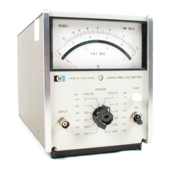
- Page 1 OPERATING SERVICE MANUAL RMS VOLTMETER 3400A :::.: :-: :: :: : . Ol. � I �I RAN GE � . .. o • - . • HEWLETT PACKARD...
- Page 2 • PACKARD CERTIFICATIO N Hewlett-Packard Comp<lII y certifies t/'at this illstnomellt mel its published specifications at the time of shipmellt from the factory. Hewlett-Packard Company further certifies that its calibration measuremellts are traceable to the United States National Bureau of Standards, to the extellt allowed by the Bureau's calibration WARRANTY AND ASSISTANCE...
- Page 3 Page 6-9/6-10, Figure 6-4. Change value of A7A708 to Page 6·3/6-4, Schematic. Change .02IJF. .01IJF to the ·hp· Number and Page 7-4. Change CA704 to Part No. 1901-0701. Page 7-3, Table 7·1. Part description C20B to 0150-0024, 0.02 IlF.
- Page 4 MANUAL CHANOES P3gc .� Model 3400A • Page 6-9/6-10, Figure 64. e R704 om 36 Page 7-3, Table 7-1. 36.5 Delete: . Assy - ATTEN 03400-66501 Add: P.C. Assy ATTEN 03400-66511 Page 7-5 and 7·7, Table 7-1. Change the .hp.
- Page 5 OPERATING AND SERVICE MANUAL (HP PART N O . 03400-9000B) MODEL 3400A VOLTMETER SERIALS PREFIXED, 11 40A· Appendix C. Manual Backdating Changes. adapts this manual to instruments with serial numbers 0979A13725 401-, and below. and serials prefixed: 322-. 528-, 714-.
-
Page 6: Table Of Contents
Mechanical Meter Zero . 2- 8. Installation ..5-19. Power Supply Checks .. 2-10. Combining Case(- hp- Models 1051 A 5-21. Low Freque:ncy Calibration • or 1052 A).. - Page 7 Model 3400A Table of Contents LIST OP ILLUSTRATIONS Number Page Page Number I-I. -hp- Model 3400A RMS Voltmeter . 5-12. Base Q601 (feedback loop open) . 5-13 3-1. Model 3400A Controls and Indicators 6-1. Input Attenuator AI. Impedance • •...
- Page 8 ... Q RANGE " INPUT ,� , " Table 1-1. Model 3400A Specifications V OLTAGE RANGE: 1 mV to 300 V full scale, 1 2 OUTPUT NOISE: < 1 mV RMS. ranges. CREST FACTOR: (ratio of peak- to- rms ampli...
-
Page 9: General Information
Model 3400A Section I SCOPE OF MANUAL This manual contains the information necessary for oper ating and servicing the standard Model 3400A RMS Voltmeter and the Model 3400AjOption 01 RMS Voltmeter (DB scale uppermost). SECTION INFORMATION GENERAL 1-1. I NT R O DUCT I O N . -
Page 10: Power Requirements
POWER REQUIREMENTS. instrument by model number, serial number, and serial number prefix. 2 -6. The Model 3400A can be o ee rated from any ac at 48 to 440 cycles. source of 1 15- or 230- volts With the instrument disconnected from the ac power 2-16. -
Page 11: Model 3400A Controls And Indicators
Output impedance is 1000 ohms. INPUT connector: BNC jack which enables A telephone type plug for the DC OUT jack may application of input signal to instruments be purchased under -hp- Part No. 1251-0067. measuring circuits. Figure 3-1. Model 3400A Controls and Indicators... -
Page 12: Rms Value Of Ac Signals With Dc
3-6. To tur n o n the Model 3400A. proceed as follows: current and act as an rms ac-to-dc converter. Set 115/230 switch (7. Figure 3-1) to correct additional information on special applications. - Page 13 g> � P IRA NGEI r:: - ---:"I LP.:.C.:..Q�!J / _ ___ - - -__ - - - _L _____ - __ - - , ,f�rr �� TC4DI INPUT IMPEDANCE EMITTER SECOND VIDEO MODULATOR DEMOO AlTEN CONVERTER ATTEN AMPLIfiER FOlLOWERS PIOA5 �A' "", A6...
-
Page 14: General Description
R203 from loading the input signal and pre modulator to the low impedance of the direct reading meter M1 and TC402; the second thermocouple of the serves the high input impedance of the Model 3400A. thermocouple pair. The gain compensating feedback from the plate of V201 to the base of Q201 compensates for any varying 4-9. -
Page 15: Second Attenuator Assembly A
Photocells V501 and V502 in conjunction with stant gain to the ac signal being measured over the neon lamps OS501 and OS502 form a modulator cir entire frequency range of Model 3400A. See video cuit. The neon lamps are lighted alternately between amplifier assem bly schematic diagram illustrated on 90 and 100 Hz. -
Page 16: Power Supply Assembly A
-6.3 volt supply. Series Model 3400A. See power supply assembly schematic regulator Q3 acts as a dynamic variable resistor in diagram illustrated on Figure 6-4. -
Page 17: Performance Checks
-hp- Model 3440A/3443A Voltage Range: 10 mV to 100 V Adjustment and Calibration Digital Voltmeter Voltage Range: 1 m V to 300 V rms Performance Checks -hp- Model 738B Volt- Voltmeter Frequency: 400 Hz Adjustment and Calibration meter Calibrator Calibrator... -
Page 18: Introduction
Connect test setup illustrated in Figure 5-1. 5 - 5 . P E R FO R M A NC E C H ECKS. Set Model 3400A RANGE switch to 0 . 00 1 position. Adjust Voltmeter Calibrator for 0. 001 volt, 5-6. -
Page 19: Input Impedance Check
' ' frequency'' in Table 5-3; adjust oscillator output voltage t o b. Set 3400A t o 1 volt range and Test Oscillator maintain reference level set in step d . to 400 Hz. Model 3400A does not indicate within values under "meter reading"... -
Page 21: Output Noise Check
Performance Checks, Paragraph t-T, out of 5-5 to 5-14. that the Model 3400A Is adjustment. Indiscriminate adjustment of the internal controls to refine settings may actually cause more difficulty. -
Page 22: Test Equipment
R7. The range of RB is from approximately 270 ohms to 430 ohms. Connect test setup illustrated in Figure 5 - 1 . See Table 5-7. Set Model 3400A RANGE switch to 0 . 0 1 volt 5-24. I VOLT ADJUSTMENT. position. -
Page 23: High Frequency Calibration
Switch the Test Oscillator monitor switch to expand mode and set a convenient reference 5-31. Conduct a visual check of the Model 3400A for level. possible burned or loose components, loose connec tions. or any other condition which might suggest a Change Test Oscillator frequency to 100 kHz;... -
Page 24: Checking Thermocouples Tc401
5-35. The following procedure will allowyou to check on XI00 range, between ground and junction the thermocouples for proper operation in the -hp of C413 and C415 on A4 board (this step Model 3400A RMS Voltmeter. checks the resistance of heater in TC401). -
Page 25: Troubleshooting Tree
Section V 3400A Model PASSES NOTE Each check in this tree is referenced to troubleshooting procedures outlined in Table 5-6. FAILS 3400A4RO Figure Troubleshooting Tree 5-5. -
Page 26: Troubleshooting Procedure
Section V Table 5-6. Troubleshooting Procedure CHECK PROCEDURE ACTION Apply a volt 400 signal and set the 3400A to PASSE S: Proceed the 1 volt range. Measure ac signal at junction FAiLS: Proceed to C413 and C415. The reading should be between (Trouble proceeding the 240 m V and 280 m V RMS. - Page 27 Section V Model 3400A POSITIVE SIDE OF C605 Insert +IOmV signal through 499kO resistor to pin 13 on A6 Sweep 5 ms/cm Vertical 2. 0 V/cm DC coupled use 10:1 probe Figure 5-7. Input to Demodulator (feedback loop open) Table 5-6.
- Page 28 Model 3400A Section V Table 5-6. Troubleshooting Procedure (Cont'd) CHECK PROCEDURE ACTION Investigate Q605. CR604. and R615. Investigate demodulator V503 and V504. Paragraph 5-39 lor photochopper check. Check chopper ne�:m voltage. Refer to Figure 5-9 for Current variation through neans may waveform.
- Page 29 Section V Model 3400A COLLECTOR OF Q602 Insert 10 rn V signal through 499 kO resistor to pin 1 3 on A6 Sweep 5 rns/em Vertical 0. 5 V/em DC coupled use 10:1 probe Figure 5-10. Collector of Q602 (feedback loop open) Table 5-6.
- Page 30 Model 3400A Section V Table 5-6. Troubleshooting Procedure (Cont'd) CHECK PROCEDURE ACTION Investigate Q604. C605. (and demodulator) . V503 and V504. See Paragl"aph 5-39 for photochopper check. Check chopper neon voltage. Refer to Figure 5-9 for waveform. See check number for details.
-
Page 31: Thermocouple Replacement
Section V Model 3400A Table 5-6. Troubleshooting Procedure (ContI d) CHECK PROCEDURE ACTION Measure the ac signal at the negative side PASSES: Proceed to C427. The reading should be approximately 32 FAILS: Proceed to mV rms. Investigate C413 and C415. -
Page 32: Checking Photochopper Assembly
The neon subassembly does not lie flat but at an angle Place a 1 jiF capacitor (-hp- Part No. 0180- within the photochopper block. 0269) across the input leads of an ohmmeter (note the polarity of capacitor and ohmmeter Remove the neon subassembly. -
Page 33: Servicing Etched Circuit Boards
Use caution when removing them to avoid adjoining area. damaging mounted components. The assembly and -hp- Part No. are silk screened on the interior of the circuit board to identify it. Refer to Section parts replacement and -hp- part number information. -
Page 34: Accuracy, Linearity, And Dc O Ut
Madel 3400A PER FORMANCE CHECK TEST CARD Hewlett-Packard Model 3400A Tests performed by RMS Voltmeter Date Serial No. DESCRIPTION CHECK OUTPUT: ACCURACY. LINEARITY AND DC Meter Calibrator 3400A Output 0. 000990 0. 00101 0. 992 1. 008 0. 001 0. 001 0. -
Page 35: Introduction
Model 3400A Section VI SECTION VI CIRCUIT DIAGRAMS 6 - 1 . 6-5. The schematic diagrams are arranged in INTRO DUCTION. ascending order of assembly reference designation. 6-2. This section contains the circuit diagrams 6 - 6 . necessary for' the operation and maintenance of the PARTS LOCATION D IAGRAMS. - Page 36 Section Model 3400A COMPLETE REFERENCE DESIGNATIONS SHOWN. COMPONENT VALUES SHOWN AS FOLLOWS UNLESS OTHER WISE NOTED. RESISTANCE IN OHMS CAPACITANCE MICROFARADS ...l. . DENOTES POWE R LINE GROUND ( VOLTMETER CHASSIS DENOTE S CIRCUIT GROUND; ON PRINTED CIRCUIT ASSEMBLY. DENOTES ASSEMBLY.
- Page 37 (FULL SCALE DEFLECTION). A TOLERANCE OF SHOULD DE ALLOWED FOR VARIATIONS FROM INSTRUMENT TO INsrRUMENT. ALL AC VOLTAGES ARE UNDERUNED. ALL DC VOLTAGES HAVE A POLARITY INDICATION. GY TO A2-B 3400A-A-OI07 PART NO. 03400-6340 1 ) (BOARD ONLY) C402 •...
-
Page 38: Input Attenuator Ai. Impedance
Model 3400A Section - - - - - - - - - - - - - - - - - - - - - - - - - - - - - - - - - - - - - - - - -... - Page 40 Model 3400A Section � � �� -- -- -- -- -- -- -- -- -- -- -- -- -- -- -- -- -- -- '; ;; ;;:; ;; ;; E" ' " 1 0'40 � : � �� EE NOT 7.�V...
- Page 41 � V504 V502 � - R6 03 - _ E CR60 2- -R60S- " -R 60 4- • " • " C613 -C603- " � V503 V501 -CR601- � -R606- -R607- -RS09- --RS'l1 -- -R608- -CR603- -- R 6 1 9 -- �...
- Page 42 Section Model 3400A � ; �V; � ; � : ;L� � � ---- - - ---- - - ---- - - ---- - - � � � N - O - T E · � �4� 6650B) SEE APPENDIX C FOR SERIALS 714- AND BELOW.
- Page 43 • • • � o � <f�v -CR 7 I I - C706 - C R 7 12- '" -CR714- - R 7 2 2 - - R7 20- C707 0 '2. "" - R7 1 8 - -R72I - -CR715- - C R 7 1 7 - ;:,-...
-
Page 44: Power Supply A7. Schematic And Parts Location Diagram
Section -- - C712 A701 A6-5 (OS501) 0706 "r- .082 A712 220K A6-3 (OS502) "r- 56.211: +11V I GII'I' 20>-- W'����'�1 � " IRfO I S I CRTOI .my" 18>-- +15V �� IWIiT r:: � ' � =1 SERI R708 L", ,, , , , �... -
Page 45: Introduction
7-4. O R D E R ING I N F O R MATI O N. meric order of their reference designators and indi 7 -5. cates the description. -hp- part number of each part. To obtain replacement parts. address order or together with any applicable notes, and provides the inquiry to your local Hewlett-Packard Field Office. - Page 46 Model 3400A Section 3400A-RO INDEX -hp DE SCRlPTION QUANTITY PART NO. 03400-00204 Front Panel Meter Trim 1/3 module 5020-5388 Side Cover 6 1 1 sm 5000-8565 Frame Assembly 5060-0703 Top Cover (with h andle) 03400-64103 03400-00203 Rear Panel Bottom C...
- Page 47 03400-66503 Assembly: Amplifier Board 1990 -0223 Assembly: Photoconductor Chopper Part Note: matched neon subassembly of AS. (OS501 and D8502) available. -hp- Part No. 1990 -0224 03400·66508 Assembly: Chopper Amplifier Board 03400-66510 Assembly: Power Supply Board C ; fxd elect 2X4Q J.LF +30% -10% 200 vdc...
- Page 48 3400A Section Model Parts (Cont' 7-1. Table Replaceable -hp - REF ERENCE IGNAT [\1 F P,\RT NO. OESCIUPTION PART C423 Not assigned 2 . 2 Jl F *20'0 25 56289 5Ct3 0160-0128 C424 b d cer vdcw 100 pF *2% 300...
- Page 49 Section Model 3400A Table 7 - 1 . Replaceable Parts (Cont'd) -hp- REFERENCE DESCRIPTION MFR. MFR. PART NO. PART NO. DESIGNATOR Not assigned CR707 thru CR710 04713 SR1358-3 CR711. 1901-0158 Diode: 5i 200 piv CR712 CR713, 1901-0025 Diode: Si 100 piv...
- Page 50 Sectian Model 3400A Table 7-1. Replaceable Parts (Cant'd) -hp- REFERENCE DESCRIPTION MFR. PART NO. DESIGNATOR PART NO. RlOI R: Ixd met Um 10M =*: 1/4 56289 42DET-2 0698-4128 Nat assigned RI02 =*:1 % 1/8 75042 CEA T-O R: fxd met Um 9. 9...
- Page 51 Section VII Model 3400A Table 7-1. Replaceable Parts (Cont'd) -hp- REFERENCE MFR. MFR. PART NO. DESCRIPTION DESIGNATOR PART NO. 01121 CB 5135 fxd camp 51 kfl ±5% 1/4 W 0683-5135 R424 fxd comp 10 kfl ±5% 1/4 W 01121 CB 1035...
- Page 52 3400A Section Model 7 - 1 . Table Replaceable Parts (Cont'd) REFERENCE -hp - DESCRlPTlON MFH. MFH. PART NO. PART NO. DESIGNATOR nes 1/2 38.95 kll . 1/2% 1/2 91637 0727-0188 R716 (xd depe 9. 1 ± 1% 1/2 56289...
- Page 53 Model 3400A Appendix A C O D E LIST OF MANUFACTURERS ' from the Fedt ..Supp l ,. Code for Mamlflleturerl CataloJ:lnc Handbook& H (Name to Code) and 114-2 (Code followl", eode to Name) and their lateet aupplemenla. TIle date of r.y\.lon and the date of the -"ppl'me!lla used appear .1 the bc>tIom of each pac •...
- Page 54 Appendix A Model 3400A C O D E LIST OF M A N U FACTURERS ( C o n t i n u e d ) Code Addt"" Addreee Code C .. . Addre.e Manufacturer Manufacturer LRC EleelronJcI . . .
- Page 55 96067 MlcrOWlave ,Wellt, Inc, . .9.Innyvale, Cal. The foUOWIlng HP Vendors l>ave no number a6slgned In tile latest !ilJpplement to the Federal SIIllply Code for Manufacturers Handbook. OOOQQ OOOC S ..Oakland, Cal. Ilewlelt-Packard Co . , Colorado Coo!tron .
- Page 56 HEWLETT PACKARD SALES SERVICE OFFICES AFRICA. ASIA. AUSTRALIA ,... ERlC A - � � QUA ... rO'OO"" _._. NEWUO\LANO "'1110.- . G.-_� CoItoIIIOr$ ()oty "'-- ' CooDoq UI �"'KIIUN .."'-'!M GaooI'Io "" �t_ ...._ �...
- Page 57 EUROPE. NORTH AFRICA AND MIDDLE EAST UNITED STATES :��I'6S �, "" _ ..-�. l72O W. "'" Ttl (l1ll1/1 __ Sact_.� T"*'! t1o-m li'l T. 41111 tIJ·l41i,1 _ _ 00 ... , 117. ,,, .. ZUU ..� JS1'It1 T COI.OflAOO $600 s...
-
Page 58: Theory Of Operation
Q604. and change reference designator Q605 and Q606 to Q604 and Q605 respectively. Delete C305. -hp- Part No. 0160-0763. on Figure 6 - 1 and in Table 7 - 1 . CHANGE H2 Add a dashed capacitor parallel with R301 thru R304 and R306. - Page 59 Manual Backdating Changes Model 3400A Page 2 CHANGE #4 (Cont'd) Table 7 - 1 Replaceable Parts: Change R701 and R702 to -hp- Part No. 0693-473 1 , 47 kll. Delete C711 (0160-0167), C712 (0180-0282), R712 (0687 -2241). R713 (0686-2225). Q706 (1854-0022), and CR718 (1902-0046).
-
Page 60: Appendix 4-3 C
Model 3400A Appendix C • N OT E : THIS SCHEMATIC APPLIES TO SERIALS PREFIXED 322-, 40 1 -, 528-, 714- ONLY. ASSEMBLY (03400-66504) FROM A7-I'O - 17.5V PHOTOCHOPPER ASSEMBLY FROM A1-19 R607 R60S R606 - - - 3300 8200 10K... -
Page 61: Replaceable Parts
Appendix C Model 3400A Manual Backdating Changes Model 3400A Page 5 Table C-l. Replaceable Parts -hp REFERENCE DESCRlPTION PART NO. DESIGNATION ThiS table applies to instruments with serials prefixed 322-, 401-, 528-, and 714-, with chopper amplifier board 03400-66504. 03400-66508 chopper amplifier board is in... -
Page 62: Replaceable Parts
Change following components: R718 to 75 kll, -hp- Part No. 0683-7535 R730 to 1 1 kll, -hp- Part No. 0683-1135 R731 to 6 . 2 kll, -hp- Part No. 0683-6225 CHANGE #11 Page 6-9. C3A and C3B were . 01 J.lF Page 7-2. - Page 63 Change R731 to 0757-0290 R: lxd met lim 6 . 19 k 1% 1/8 CHANGE #15 Page 7-2 . The -hp- Part No. ·s listed on page 7-2 of this man ual are for brown instruments. The part numbers for blue instruments are listed below: -hp...
- Page 64 HEWLETT PACKARD PAINTED I N 03400-90008 U.S.A.
Need help?
Do you have a question about the 3400A and is the answer not in the manual?
Questions and answers