Table of Contents
Advertisement
Quick Links
Advertisement
Table of Contents
Troubleshooting

Related Manuals for Emerson AMS Trex


Summary of Contents for Emerson AMS Trex
- Page 1 User Guide , Rev 3 August 2017 ™ AMS Trex Device Communicator User Guide...
- Page 2 (2) this device must accept any interference received, including interference that may cause undesired operation. WARNING! If the Trex unit is used in a manner not specified by Emerson, the protection provided by the equipment may be impaired. WARNING! Do not directly connect the ports or terminals on the Trex unit to any main line voltage.
-
Page 3: Table Of Contents
Contents Contents Chapter 1 AMS Trex Device Communicator User Guide ..............1 User Guide overview ........................1 Documentation conventions ......................1 Technical support ...........................2 1.3.1 Information to provide to technical support ..............2 Chapter 2 AMS Trex Device Communicator overview ............... 3 Precautions for the Trex unit ...................... - Page 4 Synchronizing AMS Trex data with AMS Device Manager ..............37 2.13.1 Synchronize AMS Trex data to AMS Device Manager using USB ........38 2.13.2 Pair an AMS Trex unit with an AMS Device Manager station ........... 38 2.13.3 Unpair an AMS Trex unit ....................39 2.14 Upgrade Studio ..........................
- Page 5 Contents 3.14.1 HART icons ........................82 3.14.2 Device Setup options .....................83 3.14.3 Changing device parameters ..................84 3.14.4 Change a HART device parameter ..................85 3.14.5 Edit a HART configuration ....................86 3.14.6 Display the HART short tag or long tag ................86 3.14.7 View device alerts ......................
- Page 6 Contents 3.26.6 Gauge charts ....................... 119 3.26.7 Graphs .........................120 3.27 Disconnect a device ........................121 Chapter 4 Loop Diagnostics application ..................123 Open or close the Loop Diagnostics application ................. 124 Loop Diagnostics screen ......................124 4.2.1 View the connection diagram as a full-screen image ............127 Powering transmitters or positioners from Loop Diagnostics ............127 Voltage and current measurements in Loop Diagnostics ............
- Page 7 Contents Appendix A Troubleshooting ......................179 Troubleshoot HART communication ..................179 A.1.1 HART loops ........................181 Troubleshoot fieldbus communication ..................182 Appendix B Technical specifications ....................183 Physical specifications ........................ 183 Communication module specifications ..................184 Processor, memory, operating system specifications ..............186 Environmental specifications .....................
- Page 8 Contents User Guide...
-
Page 9: Ams Trex Device Communicator User Guide
User Guide overview • Documentation conventions • Technical support User Guide overview The AMS Trex Device Communicator User Guide is written for instrument technicians who ® ™ work with field devices, including HART and FOUNDATION fieldbus devices. The user guide describes the hardware, connections to devices, the supported applications, and the diagnostics you can run on devices, 4-20 mA current loops, or FOUNDATION fieldbus segments. -
Page 10: Technical Support
AMS Trex Device Communicator User Guide Technical support Contact your local representative or go to the AMS Trex Device Communicator website for technical support contact information. 1.3.1 Information to provide to technical support Before you call technical support personnel, have a detailed description of the issue, including the information below (if applicable). -
Page 11: Ams Trex Device Communicator Overview
• Home screen • Settings • Applications on the Trex unit • USB communication • Synchronizing AMS Trex data with AMS Device Manager • Upgrade Studio • Transferring log files to a PC • Maintenance and repair ® ™ The Trex unit supports HART... -
Page 12: Precautions For The Trex Unit
Use in an explosive environment must be in accordance with the appropriate local, national, and international standards, codes, and practices. Please review the Technical specifications and Product certifications sections of the AMS Trex Device Communicator User Guide for any restrictions associated with safe use. -
Page 13: Front View Of The Trex Unit
AMS Trex Device Communicator overview Front view of the Trex unit Figure 2-1: Front view Micro USB port (top) Power button (side) Strap connectors (side) Touchscreen Keypad Charger port for the AC adapter (side) Related information LEDs on the power module Touchscreen 2.2.1... -
Page 14: Touchscreen
AMS Trex Device Communicator overview Figure 2-2: Keypad Cancel any unsaved changes or close a menu. Similar to a Back button. Move through the menus and icons in the applications. Press the up, down, right, and left arrow keys to highlight a menu option on a screen. The right and left arrow keys also select items in a grid or on a graph, but they do not let you navigate to the next level in a menu. -
Page 15: Supported Gestures
AMS Trex Device Communicator overview CAUTION! The touchscreen display on the Trex unit could be damaged if directly impacted. To avoid damaging the touchscreen: • Use the Trex carrying case with the faceplate closed to protect the touchscreen and prevent any damage when transporting or carrying the Trex unit. -
Page 16: Enter Text, Numbers, Or Special Characters
AMS Trex Device Communicator overview Gesture Description Scroll up. Scroll right. Used to move right on graph or grid, or to view additional columns/data on a screen. Scroll left. Used to move left on graph or grid. 2.3.2 Enter text, numbers, or special characters If an option requires you to enter text, the application displays a keyboard with the permitted characters. -
Page 17: Back View Of The Trex Unit
AMS Trex Device Communicator overview Back view of the Trex unit You can access the communication module, the stand, and the power module. Figure 2-3: Back view Communication module Stand Power module Related information Communication modules Replace the stand Power module 2.4.1... -
Page 18: Communication Modules
AMS Trex Device Communicator overview Communication modules The Trex unit has two communication modules. Device Communicator communication module The Device Communicator communication module can connect to and communicate with HART and FOUNDATION fieldbus devices on an externally-powered HART loop or fieldbus segment. - Page 19 AMS Trex Device Communicator overview Figure 2-5: Device Communicator Plus communication module Power a FOUNDATION fieldbus device. You need to connect the FOUNDATION fieldbus Power Plug to the FF pwr and the positive FF terminals. Connect to a FOUNDATION fieldbus device that is externally-powered or powered by the Trex unit.
-
Page 20: Ammeter On The Device Communicator Plus Communication Module
AMS Trex Device Communicator overview WARNING! • The Trex unit cannot power a 4-wire device. Do not connect Trex unit to the power terminals of a 4-wire device. This can blow a fuse inside the Trex unit. The repair/ replacement will need to be completed at an authorized service center. -
Page 21: Install A Communication Module
AMS Trex Device Communicator overview • Avoid using the ammeter in cold or very hot temperatures. Extreme temperatures can affect the accuracy of the measurements. • Connect the mA terminals on the Trex unit to the "low-side" of the device. See the example below. -
Page 22: Remove A Communication Module
AMS Trex Device Communicator overview 2.5.3 Remove a communication module CAUTION! • Ensure sufficient grounding. Ensure the personnel, working surfaces, and packaging are sufficiently grounded when handling electrostatically sensitive parts. • Avoid touching the pins on the connectors or components. Discharged energy can affect the modules. -
Page 23: Precautions For The Power Module And Ac Adapter
• Clean the AC adapter by clearing the terminal of dirt and debris, if required. • If the AC adapter is used in a manner not specified by Emerson, the protection provided by the equipment may be impaired. • The AC adapter comes complete with interchangeable plug heads for countries UK, USA, EU and AU. -
Page 24: Leds On The Power Module
AMS Trex Device Communicator overview Figure 2-8: AC adapter Related information Precautions for the power module and AC adapter 2.6.3 LEDs on the power module The power module has six LEDs to indicate the charging status. Press the button next to the LEDs to illuminate the LEDs and view the current charge level. -
Page 25: View The Remaining Power Module Charge
AMS Trex Device Communicator overview Figure 2-9: LEDs showing approximately 100 percent charge AC adapter LED. Lights up when the AC adapter is attached to the power module. A green light indicates the power module is fully charged. An orange light indicates the power module is charging. -
Page 26: Charge The Power Module
AMS Trex Device Communicator overview Status bar 2.6.5 Charge the power module Fully charge the power module before using it in the field. The Trex unit is fully operable when the power module is charging. An overcharge condition will not occur if the AC adapter is connected after charging completes. -
Page 27: Remove The Power Module From The Trex Unit
AMS Trex Device Communicator overview 2.6.7 Remove the power module from the Trex unit CAUTION! • Ensure sufficient grounding. Ensure the personnel, working surfaces, and packaging are sufficiently grounded when handling electrostatically sensitive parts. • Avoid touching the pins on the connectors or components. Discharged energy can affect the modules. -
Page 28: Accessories
AMS Trex Device Communicator overview • Use a dry location at or near room temperature when storing the power module for an extended time. Prolonged storage at higher temperatures can reduce performance. • Ensure the remaining charge level is at or near mid-capacity when storing for an extended time. -
Page 29: Carrying Case For The Trex Unit
AMS Trex Device Communicator overview Figure 2-12: FOUNDATION fieldbus Power Plug attached to the Trex unit 2.7.2 Carrying case for the Trex unit A carrying case is available for the Trex unit to hold it and store lead sets, the AC adapter, and other accessories. -
Page 30: Power On Or Off
AMS Trex Device Communicator overview Figure 2-13: The carrying case Power on or off To power on, press and hold the power button on the upper left side of the Trex unit for one second. To power off, do one of the following: •... -
Page 31: Hard Shut Down
AMS Trex Device Communicator overview 2.8.2 Hard shut down If the Trex unit is unresponsive, do a hard shut down and then restart the Trex unit. Do not use this as your normal shut down method. Contact technical support if you need to repeatedly use the hard shut down. - Page 32 AMS Trex Device Communicator overview Figure 2-14: Home screen Application Description Field Communicator Connect to and configure HART or FOUNDATION fieldbus devices. The Trex unit can also power one HART or FOUNDATION fieldbus device. Fieldbus Diagnostics Measure the DC voltage, the noise, and the signal on a FOUNDATION fieldbus segment.
-
Page 33: Return To The Home Screen
AMS Trex Device Communicator overview Application Description ValveLink Mobile Run valve diagnostics for HART and FOUNDATION fieldbus Fisher FIELDVUE digital valve controllers. You can not power a valve using ValveLink Mobile, but you can transfer the ValveLink Mobile diagnostic files to a PC using the Trex File Transfer Utility included with the Upgrade Studio install. -
Page 34: Shortcut Bar
AMS Trex Device Communicator overview Related information Shortcut bar 2.9.3 Shortcut bar The shortcut bar lets you access additional settings for the Trex unit and the Field Communicator application. To view the shortcut bar, tap Settings on the Home screen or tap the status bar. -
Page 35: View All Open Applications
2.10.4 Wireless communication The Trex unit can connect to wireless networks to synchronize data on AMS Trex with AMS Device Manager. You can enable or disable wireless communication at any time. When the wireless radio is turned on, the wireless icon displays in the status bar. The Wi-Fi... - Page 36 Enable or disable wireless communication Connect the Trex unit to a broadcasting wireless network Connect the Trex unit to a non-broadcasting wireless network Enter a network address for an AMS Trex unit Forget a wireless network Enable or disable wireless communication Tap Settings or the status bar at the top of the screen.
- Page 37 Enter a network address for an AMS Trex unit You can specify how an AMS Trex unit connects to your network. Enter DHCP to allow a network address to be assigned, or Static to specify an IP address and/or Subnet Mask.
-
Page 38: View Information About The Trex Hardware And Operating System
Change the default connection port AMS Trex communicates with wireless networks at port 8081. If your network uses this port or restricts access to it, AMS Trex may not be able to communicate with the network. Contact your network administrator for details. -
Page 39: Enter A Name For The Trex Unit
AMS Trex Device Communicator overview Procedure Tap Settings or the status bar at the top of the screen. Tap More > About. Tap OK. 2.10.6 Enter a name for the Trex unit You can enter a name to uniquely identify the Trex unit. This is helpful if you have multiple Trex units at your site. -
Page 40: Calibrate The Touchscreen
Tap the screen as indicated. 2.10.10 Set the language on Trex Changing the display language requires the AMS Trex unit to be rebooted. Make sure you have no outstanding changes before changing the display language. Procedure Tap the toolbar at the top of the screen. -
Page 41: Power Management
AMS Trex Device Communicator overview Tap More > Memory Management. 2.10.12 Power management You can configure options to conserve power usage. Power management option Description Dim Display (Backlight) timer Dim the backlight after a period of inactivity. Suspend timer Turn off the backlight after a period of inactivity. Device communication and power are not interrupted. - Page 42 AMS Trex Device Communicator overview Related information Set the suspend timer Set the backlight timer To conserve power, set the backlight timer to automatically dim the backlight after a specified period of inactivity. The timer is enabled only when the AC adapter is not connected to the Trex unit.
-
Page 43: Enable Or Disable Automatically Connecting To Hart Devices
Tap Settings or the status bar at the top of the screen. Tap More > Field Communicator App Settings. Tap Auto-Connect to enable or disable the option. Tap OK. 2.10.14 Enable Diagnostic Logging Note You should only enable Diagnostic Logging when directed by Emerson service personnel. User Guide... -
Page 44: Applications On The Trex Unit
AMS Trex Device Communicator overview From Settings > Field Communicator App Settings tap Diagnostic Logging to ON. 2.11 Applications on the Trex unit The Home screen displays all the applications installed on the Trex unit. Open applications by tapping the icon on the Home screen. -
Page 45: Usb Communication
Synchronizing AMS Trex data with AMS Device Manager AMS Trex provides the ability to connect to AMS Device Manager and update the AMS Device Manager database with device data. The initial operation that enables this is a pairing of an AMS Trex unit with a single AMS Device Manager station. -
Page 46: Synchronize Ams Trex Data To Ams Device Manager Using Usb
Trail. Note If the AMS Trex unit Wireless is turned on and connected to a network containing the paired AMS Device Manager station, you do not need to sync using USB. Any data that is new since the last synchronization will automatically connect and download to the AMS Device Manager database. -
Page 47: Unpair An Ams Trex Unit
Connect the microUSB to the Trex unit, and then connect the USB to an AMS Device Manager system where it is currently paired. On the AMS Trex unit, tap Settings or the status bar at the top of the screen. User Guide... -
Page 48: Upgrade Studio
You will be prompted to confirm unpairing. If any data is in the process of synchronizing, it will be lost. If the AMS Trex unit is not connected to AMS Device Manager when unpairing, any data on the unit will be lost when re-connected. -
Page 49: Connect The Trex Unit To Upgrade Studio Using Usb
AMS Trex Device Communicator overview If you do not have access to a DVD drive to install Upgrade Studio, visit the support page to download the software. (http://www2.emersonprocess.com/en-US/brands/Field- Communicator/Pages/support.aspx) 2.14.1 Connect the Trex unit to Upgrade Studio using USB Prerequisites CAUTION! Remove the USB cable from the Trex unit before connecting to a device. -
Page 50: Activate The Trex Unit
Prerequisites To activate the Trex unit without using an internet connection, request an activation code by emailing Emerson at WWCS.CustServ@emerson.com or calling 888-367-3774 option 2 (U.S. and Canada) or +63.2.702.1111 (worldwide) and providing the serial number. The User Guide... -
Page 51: Transferring Log Files To A Pc
AMS Trex Device Communicator overview serial number is located on the bottom of the Trex unit, but you can also access the serial number by connecting the Trex unit to Upgrade Studio and then hovering the cursor over the Trex unit icon. -
Page 52: Maintenance And Repair
2.16.2 Calibration Calibration is not supported on the AMS Trex Device Communicator. Voltage, current, signal, and noise measurements made by the Trex unit are intended for troubleshooting purposes. NIST standards are not applicable to the AMS Trex Device Communicator. -
Page 53: Field Communicator Application
Topics covered in this chapter: • Open or close the Field Communicator application • Device interoperability • Forward Compatibility rules for saving and sending configurations to AMS Trex • Automatically detect a device • Connect - Select screen • Device connection wizard •... -
Page 54: Open Or Close The Field Communicator Application
Field Communicator application • Power and connect to a HART positioner, if the Trex unit has the Device Communicator Plus communication module. ™ • Power and connect to the Smart Wireless THUM Adapter, if the Trex unit has the Device Communicator Plus communication module. •... -
Page 55: Forward Compatibility Rules For Saving And Sending Configurations To Ams Trex
Forward Compatibility rules for saving and sending configurations to AMS Trex Note Do not edit configurations on the AMS Trex unit while connected to Configuration Management. You can edit offline configurations on the Trex unit according to forward compatibility rules: •... -
Page 56: Automatically Connect To A Hart Device
Field Communicator application Note For HART devices, the Field Communicator application can automatically detect and connect to the device if the Auto-Connect option in the Trex Settings is enabled. If this option is enabled, the device menu is displayed rather than the Device List. 3.4.1 Automatically connect to a HART device The Field Communicator application can automatically detect and connect to a HART... - Page 57 Field Communicator application • Tap HART Offline or Fieldbus Offline to simulate a device. Figure 3-1: Connect - Select screen Note To switch between HART communication and FOUNDATION fieldbus communication, you must exit and restart the Field Communicator application. After the HART or Fieldbus Device Lists are displayed, the HART or Fieldbus buttons disappear until you restart the application.
-
Page 58: Device Connection Wizard
Field Communicator application Option Description Connect to a live HART device. Tap this option if the Trex unit HART could not automatically detect or connect to the device. The device connection wizard is displayed. Simulate a connected HART device to become familiar with HART Offline the menus before configuring the device in a critical environment. -
Page 59: Status When Detecting A Device
Field Communicator application If the device connection wizard completes its process and cannot connect to the device, a message is displayed. Tap Cancel to return to the Connect - Select screen to retry the connection process. Note The selections are not saved in the device connection wizard. You need to select the desired options each time you connect to a device. - Page 60 Field Communicator application Power Status Message Description Voltage Detected on HART Typical status for connecting across HART device's communication terminals when the device is on an externally- powered loop. The detected voltage is greater than or equal to 8 volts. Voltage Detected on HART+ The detected voltage is greater than or equal to 8 volts.
-
Page 61: Online Menu Or Device Dashboard
Field Communicator application Power Status Message Description Voltage on Multiple The Trex unit has detected voltage on more than one terminal. This may be due to the following: • The AC adapter is attached to the Trex unit and is charging the power module. - Page 62 Field Communicator application Figure 3-2: Online menu example Dashboard menu A device dashboard menu displays the same parameters as the Online menu, but they are organized by tab, including: • Overview - View a graphical representation of the process variable. Tap the More arrow on the bottom right side of the screen to access additional menu items.
-
Page 63: Device Screen Layout
Field Communicator application Figure 3-3: Dashboard menu example 3.8.1 Device screen layout In the Field Communicator application, the device screens have four main parts: User Guide... - Page 64 Field Communicator application Figure 3-4: Sections of a device screen Status bar Application title bar Device menu Application bar Status bar Lets you access the settings for the Trex unit and switch to other applications. Application title bar Displays the type of device the Trex unit is connected to, the device tag (short tag or long tag), and the menu title (Online).
-
Page 65: Application Bar
Field Communicator application Device menu The menu options for a specific device type and revision. The options displayed will vary based on the device description. You can press and hold a menu item to display an additional menu that lets you view Help or add the item to the list of favorites (HART only). Application bar Displays the main groups of options for a device. -
Page 66: Menu Screen
Field Communicator application Option Description View the list of favorites for HART devices, simulate a device, or Menu connect/disconnect a device. View the process variable and configure device parameters. Online Overview (Device dashboard screen only) View a graphical representation of the process variable. The More option lets you access the device parameters. - Page 67 HART Offline or Fieldbus Offline. This option is displayed only if a device is not connected to the Trex unit. Save a configuration for this device to the AMS Trex unit. Save Config Send Config Send a configuration to a connected HART device.
- Page 68 Field Communicator application Option Description Create or edit a configuration on the AMS Trex unit. Offline Config You can also connect a device, simulate a device, or edit a configuration from the Menu screen. Figure 3-7: Menu screen for no connected HART device...
-
Page 69: Icons On The Device Menus
Field Communicator application Icons on the device menus When the Trex unit is connected to a device, the device menus may have one or more icons. Figure 3-8: Device menu with icons Icon Description The option is a parameter you can edit, such as the device tag. The option is a device method, such as a loop test. -
Page 70: Connections To Hart Devices
Field Communicator application Icon Description The option is a graph or chart. Charts display a graphic view of variables as they occur over time. The option is a gauge chart. A gauge chart formats device data into a view similar to an analog car speedometer and plots device data varying with time. The option is a grid. - Page 71 Field Communicator application Figure 3-9: HART communication terminals on the Device Communicator communication module Communicate with an externally-powered HART device Figure 3-10: HART communication terminals on the Device Communicator Plus communication module Power and communicate with a HART device. Communicate with an externally-powered HART device. Related information Wiring diagrams for HART devices and the Field Communicator application Power and connect to a HART device...
-
Page 72: Wiring Diagrams For Hart Devices And The Field Communicator Application
Field Communicator application 3.10.2 Wiring diagrams for HART devices and the Field Communicator application The Trex unit can communicate with a device from the control room, on the bench, or any wiring termination point in the loop. Connect the lead set to the Trex unit and to the communication terminals on the device or across the resistor. - Page 73 Field Communicator application Figure 3-12: Connect to a powered WirelessHART device (with its battery attached) CAUTION! Do not use the Trex unit to power a WirelessHART device. Providing power to a WirelessHART device may damage the device. Device connection wizard prompts Answer Do you intend to provide power from the Trex unit? Leads are attached to:...
- Page 74 Field Communicator application Device connection wizard prompts Answer Do you intend to provide power from the Trex unit? Leads are attached to: Transmitter Change Polling Option? Tap Yes if the device is not at address zero. Figure 3-14: Connect to an externally-powered 2-wire HART transmitter and use the Trex internal resistor Note The Trex unit must be connected in series with the transmitter to use the internal resistor.
- Page 75 Field Communicator application Figure 3-15: Connect to a 4-wire HART transmitter If you have a 250 Ohm resistor, you can insert it in between the device terminals and connect the lead set across the resistor. Otherwise, you can enable the internal resistor in the device connection wizard. Note Ensure you review the device documentation for connecting/setting up HART communication.
- Page 76 Field Communicator application Device connection wizard prompts Answer Do you intend to provide power from the Trex unit? Are you providing power to a transmitter or Positioner positioner? Change Polling Option? Tap Yes if the device is not at address zero. Increase loop current? Tap Yes to increase the current from 4 mA to another value, if the device did not initially...
-
Page 77: Wiring Diagrams For The Smart Wireless Thum
Field Communicator application ™ 3.10.3 Wiring diagrams for the Smart Wireless THUM Adapter and the Field Communicator application Below each diagram, a table lists the expected prompts from the device connection wizard and the answers to select to complete the connection. If you are using a WirelessHART adapter that is not the Smart Wireless THUM adapter, review its documentation before connecting the Trex unit. - Page 78 Field Communicator application Figure 3-19: Power and communicate with the THUM adapter attached to a HART transmitter Note If you want to communicate with the THUM adapter rather than the device, ensure the Auto-Connect option for the Field Communicator Settings is disabled. This allows the Field Communicator application to detect both the THUM adapter and the transmitter, and let you select which one to communicate with.
- Page 79 Field Communicator application Figure 3-20: Communicate with the THUM adapter attached to a powered HART transmitter Connect the lead set to the yellow and white wires. Note If you want to communicate with the THUM adapter, ensure the Auto-Connect option for the Field Communicator Settings is disabled.
- Page 80 Field Communicator application Figure 3-21: Communicate with the THUM adapter powered by a voltage source Connect the lead set to the yellow and white/black wires. Voltage source. Device connection wizard prompts Answer Do you intend to provide power from the Trex unit? Leads are attached to: Transmitter Change Polling Option?
-
Page 81: Hart Device List
Field Communicator application Device connection wizard prompts Answer Do you intend to provide power from the Trex unit? Leads are attached to: Positioner Change Polling Option? Tap Yes and select 63. 3.10.4 HART Device List The Device List displays the devices that the Trex unit has detected. Each device is listed by its tag and address. -
Page 82: Internal Resistors
Field Communicator application Figure 3-23: HART Device List 3.11 Internal resistors The Trex unit has internal resistors that can be used when the Trex unit powers a HART transmitter, or when the HART transmitter is on a 4-20 mA current loop without a resistor. The resistors are enabled through the device connection wizard in the Field Communicator application. - Page 83 Field Communicator application Available resistors Resistor 167 Ohm Used when the Trex unit powers a HART transmitter. This is the only resistor that is available when the Trex unit powers a transmitter. The 167 Ohm resistor is available due to Intrinsic Safety limitations when the Trex unit powers a device.
-
Page 84: Enable Or Disable The Internal Resistors
Field Communicator application Figure 3-25: Connection for using the Trex internal resistor for an externally- powered 2-wire transmitter Voltage source For 4-wire transmitters, the Trex unit must be connected in parallel. In the diagram below, the Trex internal resistor is enabled in the HART terminals. Figure 3-26: Connection for using the internal resistor for a 4-wire transmitter Voltage source... - Page 85 Field Communicator application If the Trex unit is connected to an externally-powered HART transmitter, the device connection wizard prompts you if you want to increase loop resistance. The Trex unit then selects the 250 Ohm or 500 Ohm resistor; you cannot select a specific value. The selected resistor value is not displayed on the screen.
-
Page 86: Power And Connect To A Hart Device
Field Communicator application Figure 3-28: Connection for an externally-powered 2-wire transmitter A. Voltage source b. Tap HART. c. Tap No when asked if you intend to provide power. d. Tap Transmitter. e. Tap No when asked if you want to change polling. (This assumes the device is at address zero.) f. - Page 87 Field Communicator application CAUTION! • The Trex unit cannot power a 4-wire device. Do not connect Trex unit to the power terminals of a 4-wire device. This can blow a fuse inside the Trex unit. The repair/ replacement will need to be completed at an authorized service center. •...
-
Page 88: Power And Connect To A Smart Wireless Thum Adapter
Field Communicator application In the Field Communicator application, tap HART. Tap Yes when prompted if you want the Trex unit to power the device. Tap Transmitter or Positioner. If you selected Positioner, the Trex unit provides power and 4 mA. Follow any additional prompts. -
Page 89: Connect To An Externally-Powered Hart Device
Field Communicator application Figure 3-31: THUM adapter wiring with 250 Ohm resistor In the Field Communicator application, tap HART. Tap Yes when prompted if you want the Trex unit to power the device. Tap Positioner. When prompted, change the polling address to 63. Follow any additional prompts to connect to the THUM adapter. -
Page 90: Online Hart Devices
Field Communicator application Open the Field Communicator application. The Trex unit may automatically detect or connect to the device. If the Trex unit does not automatically connect to the device, tap HART and do the following: a. Tap No when asked if you want to provide power from the Trex unit. b. -
Page 91: Device Setup Options
Field Communicator application Related information Status bar 3.14.2 Device Setup options The Device Setup menu accesses every configurable parameter for the connected device. Some devices may not display a Device Setup menu or it may display different options. The list below is a general overview of the options. See the device documentation for more information. -
Page 92: Changing Device Parameters
Field Communicator application Detailed Setup The Detailed setup menu provides access to every editable device parameter and all device functions. The Detailed setup menu varies from one HART device to another. Functions in this menu can include tasks such as characterization, configuration, and sensor and output trims. -
Page 93: Change A Hart Device Parameter
Field Communicator application Figure 3-32: Changed parameter is highlighted yellow 3.14.4 Change a HART device parameter You can modify one or more parameters and then send the changes to the device. Procedure Connect to the HART device. Go to the parameter you want to change. See the device documentation for more information. -
Page 94: Edit A Hart Configuration
Field Communicator application Tap the Send icon in the upper right corner. A list of all the changes you made is displayed. Review the change. Tap Discard to undo the change and close the screen. Tap Cancel to keep the change and send it to the device at a later time. - Page 95 Field Communicator application Note The selected tag is not retained the next time you connect to the device. You need to select the desired tag each time you connect the device. If you want to change the value of the HART tag, see the device documentation for more information.
-
Page 96: View Device Alerts
Field Communicator application The displayed tag changes. 3.14.7 View device alerts Connect to a HART device. If the device has alerts, tap Alerts at the top of the screen. The list of alerts is displayed. Figure 3-34: Alerts button Tap OK. User Guide... -
Page 97: Send A Configuration To A Connected Hart Device
Field Communicator application 3.14.8 Send a configuration to a connected HART device Prerequisites You must have at least one configuration saved in the Trex unit for the connected device type. Procedure Connect to the HART device. Tap the Menu tab in the application bar. Tap Send Config. -
Page 98: Create A Hart Configuration
Field Communicator application 3.15.1 Create a HART configuration Create a new configuration for a specific device type and revision. You can then apply this configuration to multiple devices. Procedure In the Field Communicator application, tap HART Offline. Tap Offline Config > New. Tap a manufacturer. -
Page 99: Copy A Hart Configuration
Field Communicator application Tap Save when you finish editing the parameters. If necessary, enter a new configuration name. Tap OK. 3.15.3 Copy a HART configuration You can create a copy of a saved configuration. Procedure In the Field Communicator application, tap HART Offline. Tap Offline Config >... -
Page 100: Open A Menu Item From The Favorites List
Field Communicator application If the device description for the device has predefined favorites, they are available from the Favorites screen. Also, some devices may include additional menu items in the favorites list. 3.16.1 Open a menu item from the favorites list The Favorites option is supported for only HART devices. -
Page 101: Remove A Menu Item From The Favorites List
Field Communicator application Figure 3-35: Favorites menu Tap Add To Favorites. The menu item is added to the favorites. To verify the option was added, go to Menu > Favorites. 3.16.3 Remove a menu item from the favorites list Note Some devices have default options, such as tag or range values, already in the favorites list. -
Page 102: Polling Options For Hart Devices
Field Communicator application Tap Menu > Favorites. Press and hold a menu item displayed in the Favorites list. Tap Remove From Favorites. 3.17 Polling options for HART devices The Field Communicator application uses the HART polling options to search for connected devices. -
Page 103: Connections To Foundation Fieldbus Devices
Field Communicator application Procedure Connect the lead set to the Trex unit and to the device. Open the Field Communicator application. If the Trex unit does not automatically connect to the device, tap HART. Follow the prompts to connect to the device. Tap Yes when prompted if you want to change the polling option. -
Page 104: Precautions For Using The Trex Unit With Foundation Fieldbus Devices
Field Communicator application 3.18.1 Precautions for using the Trex unit with FOUNDATION fieldbus devices WARNING! If a fieldbus segment is connected to a host system, the changes made with the Trex unit may not be recorded in the host system’s permanent database. Verify the changes in the database. Otherwise, this could cause unpredictable results and, depending upon your application, process disruption leading to property damage, serious injury, or death. - Page 105 Field Communicator application Figure 3-36: FOUNDATION fieldbus Power Plug attached to the Trex unit Figure 3-37: FOUNDATION fieldbus terminals on the Device Communicator communication module FF terminals to communicate with a FOUNDATION fieldbus device User Guide...
-
Page 106: Wiring Diagrams For Foundation Fieldbus Devices And The Field Communicator Application
Field Communicator application Figure 3-38: FOUNDATION fieldbus terminals on the Device Communicator Plus communication module FF pwr terminal provides power, power conditioning, and two terminators to one FOUNDATION fieldbus device. Use the FOUNDATION fieldbus Power Plug to connect this terminal to the red FF terminal. - Page 107 Field Communicator application Figure 3-39: Power and connect to a FOUNDATION fieldbus device To power a FOUNDATION fieldbus device, the Trex unit needs the FOUNDATION fieldbus Power Plug. When the Trex unit powers a device, it also provides two terminators and a power conditioner. WARNING! The Trex unit can power only one FOUNDATION fieldbus device.
-
Page 108: Link Active Scheduler (Las)
Field Communicator application Related information FOUNDATION fieldbus communication terminals Power and connect to a FOUNDATION fieldbus device Connect to an externally-powered FOUNDATION fieldbus device 3.18.4 Link Active Scheduler (LAS) All fieldbus segments have only one Link Active Scheduler (LAS). The LAS operates as the bus arbiter for the segment. -
Page 109: Power And Connect To A Foundation Fieldbus Device
Field Communicator application Figure 3-41: Fieldbus Device List 3.19 Power and connect to a FOUNDATION fieldbus device The Trex unit can power one FOUNDATION fieldbus device. The Trex unit can provide approximately 10 volts at 25 mA to power a FOUNDATION fieldbus device. (The Trex unit will draw approximately 12 mA when it is online). - Page 110 Field Communicator application Note When the Trex unit powers a FOUNDATION fieldbus device, two internal terminators and a power conditioner are applied. Ensure the device is not connected to a fieldbus segment, even if the segment is unpowered. CAUTION! Remove the USB cable from the Trex unit before connecting to a device. WARNING! Do not add any external power to the device when the Trex unit is powering the device.
-
Page 111: Connect To An Externally-Powered Foundation Fieldbus Device
Field Communicator application From the Device List, tap the desired device. The device menu displays. To stop powering the FOUNDATION fieldbus device, close the Field Communicator application or remove the lead set. Related information Wiring diagrams for FOUNDATION fieldbus devices and the Field Communicator application Disconnect a device 3.20... -
Page 112: Online Foundation Fieldbus Devices
Field Communicator application Open the Field Communicator application. If the Trex unit does not automatically find the device, tap Fieldbus on the Connect - Select screen. From the Device List, tap the desired device. The device menu is displayed. To disconnect a device, tap Menu > Disconnect, or remove the lead set. Related information Wiring diagrams for FOUNDATION fieldbus devices and the Field Communicator application... - Page 113 Field Communicator application Fieldbus block modes The resource, transducer, and all function blocks in the device have modes of operation. These modes control the operation of the block. Every block supports both automatic (Auto) and out of service (OOS) modes. Other types of modes that may also be supported are Cas, RCas, ROut, IMan and LO.
- Page 114 Field Communicator application You can change the mode for a block from the Block List, or you can open a specific block and change the mode. Procedure Connect to a FOUNDATION fieldbus device. To change the modes for one or more blocks on the Block List: a.
- Page 115 Field Communicator application Figure 3-44: Example Mode button in a block b. Tap the mode button at the top of the screen. c. Select the desired mode for the block. d. Tap OK. The change is highlighted yellow. e. Tap Send. f.
-
Page 116: Run A Method
Field Communicator application Note You cannot schedule IO blocks when the device is commissioned or a host/linking device is detected on the fieldbus segment. To schedule IO blocks, use the host system or remove the device from the fieldbus segment and connect it directly to the Trex unit. Procedure Connect to the FOUNDATION fieldbus device. -
Page 117: View The Device Information
Field Communicator application 3.21.4 View the device information You can view the physical device tag, device address, device ID, and device revision. You can also view this information by tapping the device tag at the top of the screen and selecting DD Information. -
Page 118: Change The Tag For A Foundation Fieldbus Device
Field Communicator application Go to the parameter you want to change. See the device documentation for more information. Each device uses different menus. If prompted, select if the device is commissioned. Change the parameter. Note The Trex unit may disconnect from the device after you make the change. If this occurs, the change is automatically sent to the device without any additional input from you. -
Page 119: Guidelines For Changing The Device Address
Field Communicator application Tap the device to reconnect to it. 3.21.7 Guidelines for changing the device address Note The physical address of a FOUNDATION fieldbus device is read-only when the device is commissioned or a host/linking device is detected on the fieldbus segment. To change the device address, use the host system or remove the device from the fieldbus segment and connect it directly to the Trex unit. -
Page 120: Polling For Foundation Fieldbus Devices
Field Communicator application Tap OK on the message that indicates the device has been disconnected from the Trex unit. The Device List appears and displays the device at the new address. Tap the device to connect to it. 3.21.9 Polling for FOUNDATION fieldbus devices When you connect the Trex unit to a FOUNDATION fieldbus device, the Field Communicator application polls the most common addresses for a fieldbus segment. -
Page 121: Simulate A Live Device
Field Communicator application Select Basic or Master, and tap OK. Tap OK to restart the device and apply the changes. The Trex unit displays the Device List. 3.22 Simulate a live device You can simulate an online connection to a device without connecting to a device. Simulation mode is a training tool that helps you become familiar with devices before configuring them in a critical environment. -
Page 122: View The Device Description Information
Field Communicator application Tap Cancel to return to the offline menu. 3.24 View the device description information You can view information about the connected device, including the manufacturer, device type, device revision, and device description revision. The Tag and Long Tag options displayed below appear for only HART revision 7 devices. Procedure Connect to the HART or FOUNDATION fieldbus device. -
Page 123: View Help For A Device Parameter
Field Communicator application Tap DD Information. The device description information is displayed. Tap OK. 3.25 View Help for a device parameter Go to the desired parameter in the connected device. Press and hold the parameter. A menu appears. Tap Help. The help text is displayed. -
Page 124: Charts
Field Communicator application Some images have links that let you run methods or view additional menus. If an image has a link, a button is displayed at the bottom of the screen. 3.26.2 Charts Charts display a graphic view of variables as they occur over time. There are four types of charts: Chart type Description... -
Page 125: Horizontal Bar Charts
Field Communicator application Figure 3-47: Strip chart 3.26.4 Horizontal bar charts A horizontal bar chart formats device data into bars from left to right and varies with time. Use the drop-down list to select the variable you want to highlight. Additional horizontal bars may be present if more than one variable is defined for the option you selected in the drop-down list. -
Page 126: Vertical Bar Charts
Field Communicator application Figure 3-48: Horizontal bar chart 3.26.5 Vertical bar charts A vertical bar chart formats device data into bars from bottom to top and varies with time. Use the drop-down list to select the variable you want to highlight. Additional vertical bars may be present if more than one variable is defined for the option you selected in the drop- down menu. -
Page 127: Gauge Charts
Field Communicator application Figure 3-49: Vertical bar chart 3.26.6 Gauge charts A gauge chart formats device data into a view similar to an analog car speedometer and plots device data varying with time. Use the drop-down list to select the variable you want to highlight. -
Page 128: Graphs
Field Communicator application Figure 3-50: Gauge chart 3.26.7 Graphs A graph is a snapshot line drawing of device information. Use the drop-down list to select the variable you want to highlight. Additional variables may be present if more than one is defined for the option selected in the drop-down list. -
Page 129: Disconnect A Device
Field Communicator application Figure 3-51: Graph 3.27 Disconnect a device Prerequisites Before you disconnect the Trex unit from a device, resolve any unsent data to the device. Procedure Tap Menu > Disconnect or remove the lead set from the device or the Trex unit. The Trex unit detects the loss of voltage or current and stops communicating with the device. - Page 130 Field Communicator application User Guide...
-
Page 131: Loop Diagnostics Application
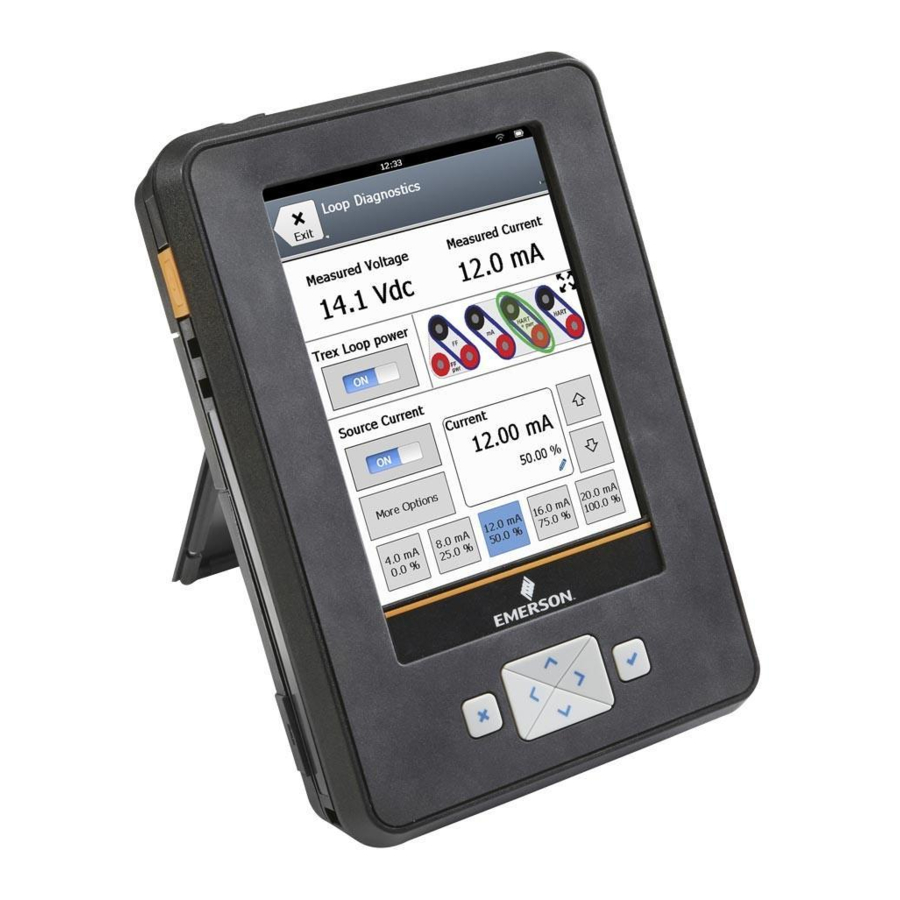
Loop Diagnostics application Loop Diagnostics application Topics covered in this chapter: • Open or close the Loop Diagnostics application • Loop Diagnostics screen • Powering transmitters or positioners from Loop Diagnostics • Voltage and current measurements in Loop Diagnostics • Wiring diagrams for the Loop Diagnostics application •... -
Page 132: Open Or Close The Loop Diagnostics Application
Loop Diagnostics application WARNING! The Loop Diagnostics application is a generic tool that, if misused, can interfere with an operating HART loop or may damage the ammeter in the Device Communicator Plus communication module. Do not provide Trex power or current on a loop that is in operation. Do not provide external power directly across the Trex mA terminals because this may damage the ammeter. - Page 133 Loop Diagnostics application Figure 4-1: Loop Diagnostics screen at start up Measurement section: Displays the measured voltage and current. The measurements begin when the Loop Diagnostics screen is displayed, and the measurements update about once per second. See Section 4.4 for more information about the terminals used for each measurement.
- Page 134 Loop Diagnostics application Figure 4-2: Loop Diagnostics when powering a positioner and taking measurements The voltage measured at the HART or HART + pwr terminals Enable/disable the Trex unit to provide power to a transmitter or power and source current to a positioner.
-
Page 135: View The Connection Diagram As A Full-Screen Image
Loop Diagnostics application 4.2.1 View the connection diagram as a full-screen image The Loop Diagnostics screen displays an image of the terminals on the Trex unit to help you make the correct connection and to see where the measurements are read. The image changes to display the correct connection for a desired task, based on the measurements or options you selected. - Page 136 Loop Diagnostics application Figure 4-3: Select the type of device to power Power a transmitter The Trex unit can power one transmitter. When the Trex unit powers a transmitter, an internal 167 Ohm resistor is used, so an external resistor is not necessary. If you already connected an external resistor in series with the red or black HART terminal on the Trex unit, there will be less voltage available for the device, especially at 20 mA.
-
Page 137: Voltage And Current Measurements In Loop Diagnostics
Loop Diagnostics application Power a positioner The Trex unit can power one positioner and set the current to 4 mA, 20 mA, or another value between 3.5 and 22.5 mA. This allows you to set the position of the valve. The Trex unit begins providing power and current when you tap OK. -
Page 138: Wiring Diagrams For The Loop Diagnostics Application
Loop Diagnostics application The HART + pwr terminals when the Trex Unit Power is on and the Trex unit is powering a positioner. Section 4.5 for more information. Wiring diagrams for the Loop Diagnostics application CAUTION! Remove the USB cable from the Trex unit before connecting to a device. WARNING! •... - Page 139 Loop Diagnostics application Figure 4-4: Power a HART transmitter The Trex unit measures both voltage and current from the HART + pwr terminals. An internal 167 Ohm resistor is used when the Trex unit powers the device. CAUTION! Do not insert a resistor in parallel with either the HART + pwr or HART terminals on the Trex unit, or in parallel with the device's communication terminals.
- Page 140 Loop Diagnostics application Figure 4-6: Power and control current to a positioner The Trex unit measures both voltage and current from the HART + pwr terminals. Figure 4-7: Connect to an externally-powered positioner in-parallel The Trex unit measures voltage from the HART terminals. Voltage measurements can be taken at various points to identify voltage drops along the loop.
- Page 141 Loop Diagnostics application Figure 4-8: Connect to an externally-powered positioner in-series The Trex unit controls current from the HART terminals. Voltage source Figure 4-9: Control current to simulate a transmitter on an externally-powered loop The Trex unit controls current from the HART terminals, which simulates a transmitter. The Trex unit controls current the same way as a transmitter controls current.
- Page 142 Loop Diagnostics application Figure 4-10: Read current for an analog output loop check The Trex unit is connected to an analog output and is measuring current from the mA terminals. You can connect the Trex unit at various points on the current loop, including a junction box, device connection point, etc.
- Page 143 Loop Diagnostics application Figure 4-12: Measure current from an externally-powered transmitter device with test terminals The Trex unit measures current from the mA terminals on an externally-powered loop without breaking the loop and connecting the ammeter (mA terminals) in-series. WARNING! Do not insert a resistor in parallel with either the HART + pwr or HART terminals on the Trex unit, or in parallel with the device's communication terminals.
-
Page 144: Power A 2-Wire Transmitter
Loop Diagnostics application Figure 4-13: Power and control current to simulate a transmitter on an unpowered loop Note The Trex unit is connected to a 4-wire terminal block. Consult the host documentation for more information. Analog input Power a 2-wire transmitter The Trex unit can provide up to 16 volts (at 22.5 mA) to power a HART device. -
Page 145: Power A 2-Wire Transmitter And Measure Analog Output
Loop Diagnostics application Procedure Connect the lead set to the HART + pwr terminals on the Trex unit and to the transmitter. Figure 4-14: Power a 2-wire transmitter On the Loop Diagnostics screen, tap Trex Unit Power. Tap Power Transmitter. The Trex unit uses an internal resistor while powering the device. - Page 146 Loop Diagnostics application CAUTION! Do not add any external power to the device when the Trex unit is powering the device. This can blow a fuse inside the Trex unit. The repair/replacement will need to be completed at an authorized service center. Ensure the device is disconnected from the loop/segment and no other wires are connected to the device before providing power from the Trex unit.
-
Page 147: Power A Positioner
Loop Diagnostics application Power a positioner If you try to apply power from the Trex unit when the device is externally-powered, the Loop Diagnostics application prevents the Trex unit from supplying power. This protects the Trex unit from damage. CAUTION! Remove the USB cable from the Trex unit before connecting to a device. -
Page 148: Stroke A Valve
Loop Diagnostics application Loop Diagnostics is now powering the positioner and measuring voltage and current. The Trex Unit Current option is also enabled. To change the current value, tap one of the quick current buttons (4 mA, 8 mA, 12 mA, 16 mA, 20 mA), or use the up and down arrow keys to manually increase the current value. -
Page 149: Settings For Controlling Current
Loop Diagnostics application Option Description Power a positioner with a specified mA Power Positioner with other mA value value. Tap OK. To change the current being supplied by the Trex unit, do one of the following: • Tap a quick current button. •... -
Page 150: Change The Scale For The Up And Down Arrow Keys
Loop Diagnostics application Figure 4-17: Quick buttons Procedure On the Loop Diagnostics screen, tap Trex Unit Current > More Options > Quick Button Selection. More Options does not appear unless the Trex Unit Power or Trex Unit Current is enabled. Tap one of the Quick Button Selection options. -
Page 151: Set The Duration To Change The Current
Loop Diagnostics application Procedure On the Loop Diagnostics screen, tap Trex Unit Current > More Options > Arrow Scaling for More Options does not appear unless the Trex Unit Power or Trex Unit Current is enabled. Enter a value between 0.04 to 10.00 mA. Tap OK. - Page 152 Loop Diagnostics application Checks before installation Before a device is installed, verify its operation. You can enable the Trex Unit Power option to power the device. For a transmitter, use the Trex unit to power the transmitter and measure the 4-20 mA output. For a positioner, use the Trex unit to power the positioner, control the current, and ensure the positioner moves as expected when the current changes.
-
Page 153: Measure Voltage On An Externally-Powered Loop
Loop Diagnostics application • Simplify the problem by removing one or more components from the HART loop. Attempt tasks from the "Checks after installation" section. • Isolate the device and perform tasks from "Checks before installation." 4.11.1 Measure voltage on an externally-powered loop You can use the HART terminals on the Trex unit to measure the voltage on an externally- powered device/loop. -
Page 154: Simulate A Transmitter On An Externally-Powered Loop For A Loop Check
Loop Diagnostics application The Trex unit can be connected at various point along the loop to measure current. Figure 4-18: Example connection for measuring current A. Analog output. In the Loop Diagnostics application, view the measured current at the top of the screen. -
Page 155: Simulate A Transmitter On An Unpowered Loop For A Loop Check
Loop Diagnostics application Figure 4-19: Connection for controlling current A. Analog input. On the Loop Diagnostics screen, tap Trex Unit Current. Tap one of the quick buttons to increase the current being supplied, use the up and down arrow keys, or tap the pencil icon to enter a new value. Verify the digital control system is reading the same current value. - Page 156 Loop Diagnostics application Figure 4-20: Connection for providing power and simulating a transmitter A. Analog input. On the Loop Diagnostics screen, tap Trex Unit Power. Tap Simulate Transmitter with 4 mA. Change the current value by pressing the quick buttons or the up and down arrow keys.
-
Page 157: Fieldbus Diagnostics Application
Fieldbus Diagnostics application Fieldbus Diagnostics application Topics covered in this chapter: • Open or close the Fieldbus Diagnostics application • Fieldbus Diagnostics Overview screen • GOOD, BAD, and CHECK measurements in Fieldbus Diagnostics • Wiring diagrams for the Fieldbus Diagnostics application •... -
Page 158: Open Or Close The Fieldbus Diagnostics Application
Fieldbus Diagnostics application Quick ad-hoc network tests to isolate issues You can use the Trex unit to connect to various connection points on the fieldbus segment to isolate an issue. For example, if the device fails to power due to a low-voltage at its terminals, use the Fieldbus Diagnostics application to measure the voltage at all cable connection points between the power supply and the device. - Page 159 Fieldbus Diagnostics application The measurements are labeled with a status of GOOD, BAD, or CHECK. You can configure the measurement criteria and ranges for the GOOD and BAD status labels. The INACTIVE status is displayed when there is no fieldbus signal, due to no device communication on the fieldbus segment.
- Page 160 Fieldbus Diagnostics application Figure 5-2: Fieldbus Diagnostics Overview screen while taking measurements View the status of the DC voltage measurement. View the status of the noise measurements. View a spectrum of the low-frequency, in-band, and high-frequency noise measurements. Set options for displaying and collecting the measurements. View the values for each measurement.
-
Page 161: Good, Bad, And Check Measurements In Fieldbus Diagnostics
Fieldbus Diagnostics application Note The Fieldbus Diagnostics application does not show which device is the LAS on the fieldbus segment. The Trex unit will become the LAS if no other LAS is on the fieldbus segment. CAUTION! The Trex unit draws approximately 12 mA from the fieldbus segment when it is online. (The Trex unit draws 0 mA when it is offline.) Ensure the power supply or barrier on the fieldbus segment has the capacity to provide this additional current when the Trex unit is online. - Page 162 Fieldbus Diagnostics application Default status labels for the DC voltage measurement Default status labels for the noise measurement Default status labels for the signal measurement If the fieldbus signal measurement has a BAD or CHECK status, an additional status note is listed on the Fieldbus Diagnostics Overview screen.
-
Page 163: Wiring Diagrams For The Fieldbus Diagnostics Application
Fieldbus Diagnostics application Fieldbus signal status note Description With in the range for all nodes All devices on the fieldbus segment have a GOOD fieldbus signal. Signal low/high on all devices All devices on the fieldbus segment have signal measurements that are higher than the set maximum value or lower than the set minimum value. - Page 164 Fieldbus Diagnostics application Figure 5-3: Power and connect to a FOUNDATION fieldbus device To power a FOUNDATION fieldbus device, the Trex unit needs the FOUNDATION fieldbus Power Plug. When the Trex unit powers a device, it also provides two terminators and a power conditioner. WARNING! The Trex unit can power only one FOUNDATION fieldbus device in a bench setup.
-
Page 165: Power A Foundation Fieldbus Device
Fieldbus Diagnostics application Power a FOUNDATION fieldbus device The Trex unit can power one FOUNDATION fieldbus device. The Trex unit can provide approximately 10 volts at 25 mA to power a FOUNDATION fieldbus device. (The Trex unit will draw approximately 12 mA when it is online) If you try to apply power from the Trex unit when the device is externally-powered, the Fieldbus Diagnostics application prevents the Trex unit from supplying power. -
Page 166: Connect To An Externally-Powered Fieldbus Segment
Fieldbus Diagnostics application Figure 5-5: Connection for powering a FOUNDATION fieldbus device A. FOUNDATION fieldbus Power Plug On the Fieldbus Diagnostics Overview screen, tap Power Supply to enable power to the device. The Trex unit powers the device. To stop power, tap Power Supply or disconnect the lead set from the Trex unit. Connect to an externally-powered fieldbus segment You can connect the Trex unit at various points, including at the device terminals or a point... -
Page 167: Measure The Dc Voltage, Noise, And The Fieldbus Signal
Fieldbus Diagnostics application Figure 5-6: One connection option for connecting to the fieldbus segment A. Terminators B. Power conditioner C. Fieldbus power supply D. Host system Open Fieldbus Diagnostics. The Trex unit connects to the device/fieldbus segment and begins the measurements. -
Page 168: Details Screen
Fieldbus Diagnostics application The measurement status appears on the screen. c. If the signal measurement status is "INACTIVE" or if you want to identify the device tags that are listed on the Details screen, tap Go Online. If the FOUNDATION fieldbus device is not powered, do the following: a. -
Page 169: View The Live Measurement Values In Fieldbus Diagnostics
Fieldbus Diagnostics application View the live measurement values in Fieldbus Diagnostics The Fieldbus Diagnostics Overview screen displays measurements as a GOOD, BAD, or CHECK status. However, you can view the actual measurement values in real-time. The Details screen also displays all the devices found on the fieldbus segment. If you selected Go Online, the devices are listed by tag and address. -
Page 170: Noise Spectrum
Fieldbus Diagnostics application Figure 5-7: Help example Tap OK to close the Help screen. 5.11 Noise spectrum The noise spectrum gives you a real-time view of the different types of noise that were detected on the fieldbus segment. Various conditions can cause different types of noise. The spectrum displays the measurements grouped by low frequency, in-band, and high frequency noise. - Page 171 Fieldbus Diagnostics application The noise spectrum shows the highest measurement in mV (peak-to-peak) outlined in black. Tap Reset Peak to clear the black outline and have it reset to the most recent highest peak. For example, use Reset Peak to clear a noise spike that was detected when connecting the Trex unit or other hardware to the fieldbus segment.
- Page 172 Fieldbus Diagnostics application Figure 5-8: Highest amplitude marked with black outline How noise affects the fieldbus segment The fieldbus segment can function properly with large amounts of low-frequency noise, small amounts of in-band noise, or moderate amounts of high-frequency noise. In-band noise is most likely to directly impact fieldbus communications.
-
Page 173: View A Spectrum Of The Noise Measurement
Fieldbus Diagnostics application 5.11.1 View a spectrum of the noise measurement You can view the noise spectrum that displays the levels of low frequency (870 Hz - 9 KHz), in-band (9 KHz - 39 KHz), and high frequency noise (39 - KHz - 100 KHz). Note Before taking a noise measurement, remove the AC adapter from the Trex unit, if it is connected. -
Page 174: Settings
Fieldbus Diagnostics application Figure 5-9: Example of noise spectrum If necessary, tap Reset Peak to clear the peak on the spectrum. 5.12 Settings Within the Fieldbus Diagnostics application, you can change the following settings: • View or hide the minimum, maximum, and average values for each measurement. •... -
Page 175: View Or Hide The Minimum, Maximum, And Average Values For A Measurement
Fieldbus Diagnostics application 5.12.1 View or hide the minimum, maximum, and average values for a measurement The minimum, maximum, and average values are displayed on the Details screen. By default, these values are displayed. Procedure On the Fieldbus Diagnostics Overview screen, tap Settings. Tap the Show Min Max Avg box to show or hide these values. -
Page 176: Set The Range Of Values For The Good And Bad Status
Fieldbus Diagnostics application Tap OK. 5.12.4 Set the range of values for the GOOD and BAD status You can set the range of measurement values that determine the GOOD and BAD status for a measurement on the Fieldbus Diagnostics Overview screen. Any measurements within the set minimum and maximum values are labeled GOOD. -
Page 177: Log File Overview
Fieldbus Diagnostics application File type The measurements are saved to a comma-separated values (.csv) log file on the Trex unit, ® so you can use several different spreadsheet programs, including Microsoft Excel, on the PC to analyze and chart the data at a later time. You cannot view the contents of the log file from the Trex unit. - Page 178 Fieldbus Diagnostics application signal measurements are organized by valid fieldbus address (16 -255), one column for each address. The value in each column is the measurement value in mV (peak-to-peak). Scroll to the right to see all columns in the log file. Figure 5-10: Example log file Measurement intervals...
-
Page 179: Enable Or Disable Logging
Fieldbus Diagnostics application 5.13.2 Enable or disable logging Use the logging option to save measurements to a comma-separated values (.csv) log file. You can save one set of measurements or append additional sets of measurements that you collect at a later date. Appending the measurements lets you create a trend/report of the fieldbus segment. -
Page 180: Save Measurements To An Existing Log File
Fieldbus Diagnostics application Option Description Select Append to save the measurements to an existing Save Option log file of the same filename, or select Replace to overwrite the data in an existing log file with the same filename. Append is the default option. The log file is limited to 176 MB. -
Page 181: Transfer A Fieldbus Diagnostics Log File From The Trex Unit To A Pc
Fieldbus Diagnostics application Procedure On the Fieldbus Diagnostics Overview screen, tap Logging. The Log Settings screen lists the current file name that is being used. Check the name listed in the File Name field. If it is the desired file, tap OK. If the desired file name is not listed, do the following: a. -
Page 182: Troubleshooting Fieldbus Diagnostics
Fieldbus Diagnostics application 5.14 Troubleshooting Fieldbus Diagnostics If you see a measurement labeled BAD or CHECK, tap Details to view the values for each measurement. Press and hold a measurement value on the screen to view Help that describes overview or troubleshooting information. You can also access the Help menu by holding the checkmark button on the keypad when a measurement value is selected. - Page 183 Fieldbus Diagnostics application DC voltage measurement Possible cause Action Higher than expected There may be more than one Ensure there is only one voltage voltage source on the fieldbus source. segment. The power supply's voltage Verify the power supply's setting may be set too high. voltage setting is correct.
- Page 184 Fieldbus Diagnostics application High-frequency noise Possible cause Action Higher than expected There may be loose wire Check for loose connections. connections. Vibration from nearby motors or wind gusts may cause loose connections to be displayed as high-frequency noise. Water or moisture may be in Check the device's terminal the device's terminal housing.
- Page 185 Fieldbus Diagnostics application Fieldbus signal Possible cause Action There are too many terminators Review the number of on the fieldbus segment. terminators. A fieldbus segment should have two terminators. Note The Trex unit adds two terminators when it powers a FOUNDATION fieldbus device.
- Page 186 Fieldbus Diagnostics application User Guide...
-
Page 187: Appendix A Troubleshooting
Troubleshooting Appendix A Troubleshooting Topics covered in this appendix: • Troubleshoot HART communication • Troubleshoot fieldbus communication Troubleshoot HART communication Symptom Possible cause Solution "No Voltage Detected" The lead set is improperly Attach the lead set to the message is displayed. connected to the device. - Page 188 Troubleshooting Symptom Possible cause Solution Device may be set to a HART Change the polling mode to address other than zero Poll by Address. (multidrop mode). Control system is An internal fuse may be blown. Connect a meter capable of communicating HART, but the measuring M ohms to the Trex unit is not communicating...
-
Page 189: Hart Loops
Troubleshooting Symptom Possible cause Solution The Trex unit needs to supply Use the device connection 1. In the Field Communicator more current than the typical 4 wizard in the Field application, connect to the mA to power a positioner. This Communicator application to positioner. -
Page 190: Troubleshoot Fieldbus Communication
Troubleshooting If an oscilloscope is available, use it to look for noise on the loop. Use a scope with differential mode capability or a battery powered/isolated scope to avoid grounding one side of the loop. Noise with a frequency of 500 Hz to 10,000 Hz is of particular interest, as this represents frequencies near the HART frequencies of 1200 and 2200 Hz. -
Page 191: Appendix B Technical Specifications
Technical specifications Appendix B Technical specifications Topics covered in this appendix: • Physical specifications • Communication module specifications • Processor, memory, operating system specifications • Environmental specifications • Intrinsically Safe electrical parameters • Power module specifications • AC adapter specifications This chapter lists the specifications for the hardware and the AC adapter. -
Page 192: Communication Module Specifications
Technical specifications Communication module specifications Device Communicator communication module Terminal Overview HART terminals The terminals enable HART communication with the Trex unit. Connectors: Two banana jack plugs. Internal fuse rating: 50 mA Optional internal resistors 250 Ohm or 500 Ohm resistor Fieldbus (FF) terminals The terminals enable FOUNDATION fieldbus communication with the Trex unit. - Page 193 Technical specifications Terminal Overview HART + pwr terminals The terminals enable HART communication with the Trex unit, and provide power to one HART device in a bench (Includes HART power supply, setup. resistors, current control, and ammeter) Connectors: Two banana plugs. Voltage measurement accuracy: +/- 2% of reading for measurements greater than 3 volts.
-
Page 194: Processor, Memory, Operating System Specifications
Technical specifications Terminal Overview FF+ pwr terminal The terminal provides power to one FOUNDATION fieldbus device in a bench setup. (Includes power supply, power conditioning, and two terminators) Connector: One banana jack plug. Voltage measurement accuracy: +/- 3% of reading. Fieldbus power supply Output: 0 mA (No device or Trex fieldbus communication) -
Page 195: Intrinsically Safe Electrical Parameters
Technical specifications Specification Value Shock The unit shall survive a 1-meter, all sides and corners drop test onto concrete. Intrinsically Safe electrical parameters Table 1: Device Communicator communication module ™ ™ FOUNDATION fieldbus FOUNDATION fieldbus ® (non-FISCO) (FISCO) HART FF + and - FF + and - HART + and - 30 Vdc... -
Page 196: Power Module Specifications
Technical specifications ™ FOUNDATION ™ fieldbus FOUNDATION fieldbus ® interface (non-FISCO) HART (FISCO) FF pwr HART + HART + FF pwr and and F- FF + and - and - FF + and - 199 mA 32 µA 105 mA 1.9 mA 199 mA 32 µA... - Page 197 Technical specifications Electrical Specification Frequency 47 - 63Hz Input current 1.6A max. at low line input and full load output Inrush current 60 A max. at 230VAC input and 25°C ambient temperature Leakage current <0.25 mA Input protection 1.6A 250VAC Fuse No load power consumption <0.5W max.
- Page 198 Technical specifications User Guide...
-
Page 199: Appendix C Product Certifications
Product certifications Appendix C Product certifications See the AMS Trex Device Communicator website for the latest certificates, declaration of conformity, and approval information. Approved manufacturing location R. STAHL HMI Systems GmbH - Cologne, Germany Labels Each Trex unit has a main unit label. An Intrinsically Safe (KL option) Trex unit has another label on the side. - Page 200 Product certifications North American certifications Class I, Division 1, groups A, B, C, D, T4. Class 1, Zone 1 AEx ia [ia Ga] [ia Da Canadian Standards IIIC] IIC T4 Gb. Association - cCSAus Ex ia [ia Ga] [ia Da IIIC] IIC T4 Gb EAC compliance EAC Ex This equipment complies with the EAC...
-
Page 201: Appendix D Wireless/Spectrum Approvals
Wireless/Spectrum approvals Appendix D Wireless/Spectrum approvals Wireless/Spectrum approvals FCC and Radio frequency radiation exposure Information: For body worn operation, this device has been tested and meets FCC RF exposure guidelines. Information sur l´exposition aux rayonnements des ondes radio : Pour le port sur une partie du corps, les directives de la FCC en rapport avec l'exposition aux fréquences RF ont été... - Page 202 (South Africa) 1.Equipment Name/Model Name: 특정소출력무선기기 (무선데이터통신 Korea 시스템용 무선기기) Trex Device Communicator . 2.Registration No.:MSIP-CMM-ERN-71354986317987 3.Applicant Name: Emerson Process Management 4.Manufacture Date: 2016 5.Manufacturer/Country of Origin: Emerson Process Management / 독일 "해당무선설비는 운용 중 전파혼신 가능성이 있음" User Guide...
-
Page 203: Glossary
Glossary Glossary Activation Activation updates the Trex unit with any needed licenses and enables the full functionality of the Trex unit. Activation also associates the Trex unit and its attached Trex modules with a user account/company. Ammeter The mA terminals on the Device Communicator Plus communication module that enable the Trex unit to measure current on a 4-20 mA current loop. - Page 204 The Trex unit is communicating with a live device. Pairing Associating an AMS Trex unit with an AMS Device Manager database using USB. Once paired, an AMS Trex unit can synchronize device data with AMS Device Manager. A Trex unit can be paired to one AMS Device Manager system.
- Page 205 Glossary Positioner A digital valve positioner. Process variable A process parameter that is being measured or controlled (for example, level, flow, temperature, mass, or density). The section of a fieldbus that is terminated in its characteristic impedance. Segment (fieldbus only) Segments are linked by repeaters to form a complete fieldbus.
- Page 206 Glossary User Guide...
-
Page 207: Index
Index Index averages set in Fieldbus Diagnostics AC adapter approvals 188, 189 charge power module connector backlight overview change specifications 188, 189 timer 33, 34 activate backlight timer applications overview Trex unit without internet connection bar charts activation horizontal overview vertical verify status basic device... - Page 208 Index configuration device address copy change 83, 84, 111 create view for fieldbus device delete device blocks edit Device Communicator communication module 86, 90 marked variable install 86, 90 rename overview save from a device remove send to HART device specifications Configure screen Device Communicator Plus communication module...
- Page 209 Index Device Setup screen signal measurement 53, 54 device tag troubleshoot change Fieldbus Diagnostics log file 83, 84, 110 view for fieldbus device transfer to a PC view/hide in Fieldbus Diagnostics fieldbus methods diagnostics fieldbus fieldbus polling 149, 150 HART fieldbus terminals Diagnostics and Service forward compatibility rules...
- Page 210 Index high-frequency noise link master device measure set fieldbus device set range of values log file view on spectrum overview 169, 170 view values save measurements to existing Home screen transfer to a PC 43, 173 icons long tag return to loop check status bar measure current...
- Page 211 AC adapter 53, 54 Fieldbus Diagnostics touchscreen 149, 150 Process Variables 83, 84 processor 30, 186 pair an AMS Trex unit paired icon range values 83–85 parameter reboot 22, 23 change resistors 84, 85, 109...
- Page 212 Index Review storage 83, 84 right arrow icon usage on device menu stand replace standby enter or leave scope chart set timer screen status bar calibrate HART icons clean overview gestures view shortcut bar overview storage specifications specifications strip chart segment stroke valve connect to...
- Page 213 Index precautions version number specifications application 2, 31 transfer data from AMS Trex to AMS Device Manager operating system 2, 30 transmitter vertical bar charts connect view spectrum 81, 103 power voltage 78, 101, 127–129, 136 power and measure analog output...
- Page 214 All rights reserved. The Emerson logo is a trademark and service mark of Emerson Electric Co. All other marks are property of their respective owners.
Need help?
Do you have a question about the AMS Trex and is the answer not in the manual?
Questions and answers