Table of Contents
Advertisement
Advertisement
Table of Contents

Related Manuals for Emerson 475


Summary of Contents for Emerson 475
- Page 1 User’s Manual Rev K May 2015 475 Field Communicator User’s Manual...
- Page 2 ©Emerson Process Management. 2015. All rights reserved. The Emerson logo is a trademark and service mark of Emerson Electric AMS, DeltaV, and ValveLink are marks of one of the Emerson group of companies. Windows is a registered trademark of Microsoft Corporation in the United States and other countries.
-
Page 3: Table Of Contents
Safety messages ....... . 9 475 Field Communicator overview ....10 Device interoperability. - Page 4 Table of Contents Adding functionality by enabling licenses ... . 33 ScratchPad ........34 Creating a new document .
- Page 5 Table of Contents Starting the Fieldbus Application ....61 Working online with fieldbus devices ....61 Connecting to a fieldbus device .
- Page 6 Table of Contents Lights ........93 Operating time .
-
Page 7: Using This Manual
Appendix A: Reference data provides physical, functional, and performance specifications. Appendix B: Product certifications contains hazardous location and international certifications, European directive information, and approval drawings. Appendix C: Graphics information contains an overview of the Graphics functionality and options in the 475 Field Communicator. www.fieldcommunicator.com... - Page 8 Introduction...
-
Page 9: Overview
EARNING THE BASICS OVERVIEW This section provides instructions on basic features and functions of the 475 Field Communicator. It also provides information on assembly, components, starting, entering standby, shutting down, settings, applications, and maintaining the 475 Field Communicator. The functionality described in this section is based on system software version 3.9. -
Page 10: Field Communicator Overview
The Field Communicator also supports multiple languages. See the readme file included with the Field Communicator Easy Upgrade Utility or www.fieldcommunicator.com for more information. Device interoperability The 475 Field Communicator is designed to operate with a wide range of HART and F fieldbus devices independent of device OUNDATION manufacturer. -
Page 11: Working In A Hazardous Area
Division 1 and Division 2, Groups A, B, C, and D locations. IS-approved 475 Field Communicators are ordered with the KL option and have an additional label on the back of the 475 that lists the approvals. See Appendix B “Product certifications” for more information about IS approvals and installations. - Page 12 Prior to first portable use, fully charge the battery. The battery can be charged separately or while attached to the 475 Field Communicator. The 475 Field Communicator is fully operable while the battery is recharging, and a full charge takes 2-3 hours. An overcharge condition will not occur if the power supply/charger remains connected.
- Page 13 2.Plug the green power supply/charger connector into the green connector on the battery. The flat side of the power supply/charger connector should face the front of the 475 or the inside of the battery, if the battery is not attached to the 475. The battery is fully charged when the light on the power supply/charger is green.
- Page 14 The battery is nearly fully charged. Yellow The battery is charging. Flashing yellow The power supply/charger is not connected to the 475 Field Communicator. Flashing yellow and The remaining charge in the battery is very low. Charging cannot occur. Contact Technical Support for more information.
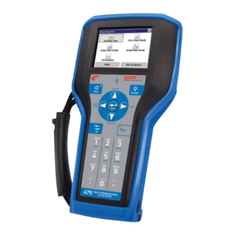
- Page 15 Learning the basics Figure 2-3. 475 Field Communicator shown with optional rubber boot ® IrDA interface HART and F fieldbus OUNDATION (top) communication terminals (top) Touch screen display ® Bluetooth light Power key and light Backlight key Strap attachment Strap attachment...
-
Page 16: Using The Touch Screen
Settings menu. See “Power Button” on page 26 for more information. The green light on the Power key flashes when you press and hold the Power key to turn on the 475 Field Communicator. The light is constant when the 475 is on, and it... - Page 17 If the Power key is pressed when there is unsent data or a device method is running, a warning message appears. Tap OK to have the 475 Field Communicator enter standby or shut down, or tap Cancel to return to the previous window.
-
Page 18: Memory
3.RAM—32MB used only for program execution. Available memory space To view the available memory in your 475 Field Communicator, connect to the Field Communicator Easy Upgrade Utility or tap the Memory icon from the Settings menu. The Field Communicator Main Menu displays the Settings menu item. -
Page 19: Accessories
Learning the basics If the selected device descriptions are already on your 475, they are removed the next time you connect the 475 Field Communicator to the Easy Upgrade Utility. You are prompted before the files are removed. See the Easy Upgrade Utility Help for more information. - Page 20 HART and fieldbus terminals on the top of the 475 Field Communicator. The side strap lets you attach a strap to the sides or back of the 475 Field Communicator, making it easy to carry. See Figure 2-5. The side strap also holds the stylus used with the touch screen.
-
Page 21: Assembly
475. 5.Align the sides of the battery with the 475 and carefully slide it forward until it is secure. 6.Carefully hand tighten the two battery retaining screws to secure the battery. -
Page 22: Removing The Battery And The System Card
3.Loosen the battery retaining screws until the top of each screw is slightly above the top of the 475 Field Communicator. 4.Slide the battery off the 475 Field Communicator. Do not pull up the battery because this could damage the connector pins. -
Page 23: Entering Standby
Figure 2-7. Field Communicator Main Menu Entering standby You can put the 475 Field Communicator into standby to save power or to reduce the boot-up time if you are using the 475 Field Communicator intermittently. Standby turns off the touch screen and areas within the 475 Field Communicator. -
Page 24: Settings
SET DEFAULT to retain this setting upon startup, or CANCEL to exit without changes. The Clock setting lets you set the date, time, and time zone on the 475 Clock Field Communicator. Configure the date by using the drop-down list. -
Page 25: Contrast
• Exp Date - displays the expiration date of the Easy Upgrade license. The date is listed as year-month-day. N/A appears if the 475 is not licensed for Easy Upgrade. -
Page 26: Power Button
1.Disconnect the power supply/charger, if it is connected to the 475 Field Communicator. 2.Tap Retrain Battery from the Settings menu. 3.Wait until the 475 Field Communicator shuts down. It may take up to several hours to discharge the battery, depending on the charge remaining when the operation began. -
Page 27: Event Capture
Event Capture which is a log of communication, input, and output that occurs between the 475 Field Communicator and a device (HART only). When working with Technical Support personnel, you may be asked to create an Event Capture file to help troubleshoot issues that cannot be easily isolated or resolved. -
Page 28: Connecting To Adevice
This mode uses a generic device description and does not display all device functionality. Three terminals for the lead set are on the top of the 475 Field Communicator. Each red terminal is a positive connection for its protocol, while the black terminal is a common terminal shared by both protocols. -
Page 29: Connecting The 475 Field Communicator Or System Card29
System Card. Limiting the number of device descriptions will free memory on your System Card. • Assign a Unit Name to a 475 Field Communicator to uniquely identify it, which is useful when connecting to a 475 Field Communicator using Bluetooth. - Page 30 Listen for PC is opened. After you select the connection type, the 475 Field Communicator waits for a connection from the PC. When the 475 is connected, a message appears and the PC name is listed in the Connected PC field on the Listen for PC window.
- Page 31 Event Captures, application licenses, and ScratchPad files. See Figure 2-3 on page 15 for the location of the IrDA interface on the 475 Field Communicator. All 475 Field Communicators can use IrDA. IrDA communication can either be built into the PC, such as a laptop, or provided through an adapter such as a USB to IrDA adapter.
- Page 32 Help for instructions to connect to those applications using IrDA. Card reader The 475 Field Communicator System Card can also communicate with the Easy Upgrade Utility using a supported Secure Digital card reader. See the readme file for the supported card readers. You can access this file from www.fieldcommunicator.com, the Resource CD or DVD,...
-
Page 33: Upgrading The 475 Field Communicator
Resource CD or DVD can provide the latest updates. Transferring the system software and device descriptions Use the Easy Upgrade Utility to transfer all the files to a connected 475 Field Communicator. You can use IrDA, Bluetooth, or a card reader to connect to the Easy Upgrade Utility and transfer the upgrades. -
Page 34: Scratchpad
See the Easy Upgrade Utility Help for more information on selecting and enabling licenses. You can send your 475 Field Communicator to a service center to have a technician enable licenses for you. Contact your sales representative for more information. -
Page 35: Creating A New Document
Learning the basics Creating a new document From the Main Page in ScratchPad, tap NEW. An empty text window and SIP keyboard appears. See Figure 2-8. You are now ready to enter text into your new document. A new document can also be created within ScratchPad by tapping the New ( ) icon in the toolbar or by selecting File | New from the menu. - Page 36 Learning the basics Pasting text 1.Copy the text to be pasted. 2.Tap a location on the screen. This is where the text will be pasted. 3.Tap Edit | Paste. You can also paste text by copying the text and tapping the Paste ( icon in the toolbar.
-
Page 37: Valvelink Mobile
A warning message appears if a fault condition is found during these tests. Calibrating It is not necessary or possible to calibrate the 475 Field Communicator. The 475 Field Communicator is a communication interface that communicates digitally with HART and F fieldbus devices. - Page 38 Learning the basics...
-
Page 39: Overview
HART ECTION FUNCTIONALITY OVERVIEW This section provides instruction on basic HART functionality in the 475 Field Communicator. It is based on the operation of the HART Application version 6.1. SAFETY MESSAGES Procedures and instructions in this section may require special precautions to ensure the safety of the personnel performing the operation. -
Page 40: Basic Features And Functions
HART Application The HART Application lets you communicate with and configure HART functionality devices that are connected to the 475 Field Communicator. You can also create and edit configurations and run diagnostics. Using a fast key sequence A fast key sequence is a sequence of numerical button presses, corresponding to the menu options that lead you to a given task. -
Page 41: Working With Offline Configurations
A device configuration is created from a connected, online HART device. A user configuration is created offline or transferred to a 475 Field Communicator from another program. Editing a device configuration within the 475 Field Communicator changes it to a user configuration. -
Page 42: Opening A Saved Configuration
HART functionality a.To change the location where the configuration is saved, double-tap Location, select an option, and tap ENTER. b.To specify a name for the configuration, double-tap Name, enter the name, and tap ENTER. c.Tap SAVE. Opening a saved A saved configuration lets you edit, copy, send, delete, or rename it. configuration You can also compare it to other saved configurations. - Page 43 Deleting a saved configuration The Delete option lets you remove saved configurations one at a time. To delete a configuration from the 475 Field Communicator storage: 1.Open a saved configuration. See “Opening a saved configuration” on page 42.
-
Page 44: Transferring Configurations To A Pc Application
Use AMS Device Manager to open, edit, compare, and transfer saved configurations. A Handheld or Field Communicator Interface kit for AMS Device Manager (version 6.2 or higher) lets you use the 475 Field Communicator with AMS Device Manager. If the System Card does not appear as a storage location in AMS... -
Page 45: Working Online With Hart Devices
Intrinsically Safe connections, see Appendix B. HART communication terminals Three terminals for the lead set are on the top of the 475 Field Communicator. Each red terminal is a positive connection for its protocol. The black terminal is a common terminal shared by both protocols. - Page 46 HART functionality Wiring diagrams Figure 3-3 shows how to connect the 475 Field Communicator to a HART loop. Figure 3-3. Connecting to a HART loop HART device RL≥250Ω Power supply Current meter Figure 3-4 shows how to connect the 475 Field Communicator directly to the terminals of a HART device.
- Page 47 2.Open the loop to allow connection of the resistor in series in the loop. 3.Close the loop using the lead set connectors. Figure 3-6 shows how to connect the 475 Field Communicator directly to the communication terminals on a wireless device.
-
Page 48: Displaying The Connected Hart Devices
HART functionality Displaying the connected After the device is connected, tap from the Field Communicator HART devices Main Menu. The HART Application automatically polls for connected devices using the selected polling options. See “Changing the HART polling options” on page 53 for information on modifying these options. NOTE Communication errors, such as a device appearing at multiple addresses, can occur when polling addresses greater than 15 on a... -
Page 49: The Hart Icon
HART functionality The HART icon A beating HART icon appears at the top of the window when the 475 Field Communicator is communicating with a device. See the table below for the icons and their meanings. Table 3-1. HART icons... -
Page 50: Displaying Device Setup Options
HART functionality Displaying Device Setup The Device Setup on the HART Online menu accesses every options configurable parameter for the connected device. Some devices may not display a Device Setup menu. Check your device documentation for more information. Double-tap Device setup to view the process variables, diagnostics and service, basic setup, detailed setup, and review menus. -
Page 51: Displaying Graphics
HART functionality Figure 3-8. Modified parameter example Detailed setup The Detailed setup menu provides access to every editable device parameter and all device functions. The Detailed setup menu varies widely from one HART device to another. Functions in this menu can include tasks such as characterization, configuration, and sensor and output trims. -
Page 52: Configuring The Hart Application
You can access the Hot key menu from any online window. To use a Hot key option: 1.Connect the 475 Field Communicator to a HART loop or device. 2.From the Field Communicator Main Menu, tap 3.Tap the Hot key ( ) from an online menu. -
Page 53: Changing The Hart Polling Options
5.Tap YES if you are sure you want to delete all the items from the Hot key menu. Tap NO to return to the Storage Cleanup menu. Changing the HART Use the HART Polling Options to configure your 475 Field Communicator polling options to automatically search for all or specific connected devices. Most HART device installations contain one device per loop and the device address is zero. - Page 54 HART functionality To change the polling option: 1.From the HART Application main menu, double-tap Utility. 2.Double-tap Configure HART Application. 3.Double-tap Polling Options. Select one of the following polling options: • Poll By Address - Lets you poll for devices at the specified addresses.
-
Page 55: Ignoring Status Messages
4.Tap Show Long Tag to display the HART long tag, or tap Show Short Tag to display the HART short tag. 5.Tap ENTER. The 475 Field Communicator continues to use the option you selected until you change the setting. Storage Cleanup The Storage Cleanup menu lets you delete the following items: •... -
Page 56: Viewing Available Device Descriptions
HART devices. Use the Field Communicator Easy Upgrade Utility to download or import new device descriptions and then transfer them to your 475 Field Communicator. See the Easy Upgrade Utility Help more information. To view the currently installed HART device descriptions: 1.From the HART Application main menu, double-tap Utility. -
Page 57: Running Hart Diagnostics
(This warning does not appear if your device is tested.) The Online menu for the simulated device appears. You can now use the 475 Field Communicator as if it were connected to the selected device and perform any online task. - Page 58 HART functionality...
-
Page 59: Fieldbus Functionality
ECTION IELDBUS FUNCTIONALITY OVERVIEW This section provides instruction on basic fieldbus functionality in the 475 Field Communicator. It is based on the operation of the Fieldbus Application version 6.1. SAFETY MESSAGES Procedures and instructions in this section may require special precautions to ensure the safety of the personnel performing the operation. -
Page 60: Basic Features And Functions
All other devices are referred to as basic devices. You can set a device to be a link master or basic device using the 475 Field Communicator. See “Setting the device to be a Link Master or Basic device”... -
Page 61: Starting The Fieldbus Application
OK to go to the Fieldbus Application main menu. Figure 4-1. Fieldbus Application Main Menu A connection warning message may appear if no communication is detected. This means that a LAS is not recognized by the 475 Field Communicator. This typically occurs when connecting to a single device. -
Page 62: Connecting To A Fieldbus Device
Fieldbus communication terminals Three terminals for the lead set are on the top of the 475 Field Communicator. Each red terminal is a positive connection for its protocol. The black terminal is a common terminal shared by both protocols. - Page 63 Fieldbus functionality Bench hook-up Figure 4-3 illustrates one method of connecting the 475 Field Communicator on a bench. For segments that are limited in size, the power conditioner and terminators can be contained in a single wiring block. Figure 4-3. Bench wiring diagram example...
- Page 64 Ensure the power supply or barrier on the fieldbus segment has the capacity to provide this additional current. If a fieldbus segment is drawing near the capacity of the segment’s power supply, connecting the 475 Field Communicator may result in loss of communication.
-
Page 65: Displaying The Connected Fieldbus Devices
LAS. The text LAS appears at the top of the window only when the 475 Field Communicator is the LAS. See Figure 4-5. If a live fieldbus device is connected to a host acting as the LAS, a precautionary message appears. -
Page 66: Displaying The Online Device
Fieldbus functionality Displaying the online Depending on the device description, the first screen displayed may be device the Block List or a Device Dashboard menu. The Block List displays the block tag, block type, and actual mode of the device blocks in the connected device. - Page 67 Fieldbus functionality Types of modes For the procedures described in this manual, it is helpful to understand the following modes: AUTO The functions performed by the block will execute. If the block has any outputs, these will continue to update. This is typically the normal operating mode.
- Page 68 Fieldbus functionality Change modes Whenever you need to change the parameters or properties of a block, you need to change the mode. A warning message may appear if the mode of any block is included in a list of parameter changes to be sent to a device.
-
Page 69: Device Blocks
Fieldbus functionality Device blocks The Block Menu is a submenu of the Block List and it displays block information for the fieldbus device to which you are connected. The Block Menu is also available from the Advanced option in a Device Dashboard menu. - Page 70 Fieldbus functionality CAUTION Changing device parameters could adversely affect the control of your process. Put the control loop in Manual/Out of Service before applying changes. Verify the output before returning the control loop to Auto. Failure to do so could result in property damage, serious injury, or death.
- Page 71 PKS, Yokogawa Stardom or CENTUM, Softing FG-100/HSE, or SMAR DF62. To change the device tag or address, use the host system or remove the device from the segment and connect it directly to the 475 Field Communicator. To display the Physical Device Tag, Device Address, Device ID, and the Device Revision: 1.Display the Live Device List;...
- Page 72 4.Double-tap Network Management. 5.Double-tap the desired label to view the values. Tap the SAVE button to save this as a text file. Connect your 475 Field Communicator to the Field Communicator Easy Upgrade Utility to transfer this file to a PC. The file appears in the User Data tab.
- Page 73 FG-100/HSE, or SMAR DF62. To instantiate or delete blocks, use the host system or remove the device from the segment and connect it directly to the 475 Field Communicator. To instantiate a block: 1.Display the Live Device List; see page 65.
- Page 74 NO to cancel the operation. NOTE Some devices restart after a block is instantiated or deleted, causing a loss in communication between the 475 Field Communicator and the device. After the device and 475 Field Communicator resume communication, the Live Device List appears.
-
Page 75: Displaying Graphics
200 and the default value for V(NUN) is zero. Narrowing the range of devices being polled provides a quicker Live Device List refresh. The DeltaV System Polling checkbox instructs the 475 Field Communicator to use the same polling scheme as DeltaV. The V(FUN) and V(NUN) options are read-only when the checkbox is selected. -
Page 76: Changing The Slot Time
Application Utility main menu, double-tap Utility and then double-tap Link Settings to access the Slot Time menu. It may be necessary to change the Slot Time to 16 to view older devices on the 475 Field Communicator Live Device List. -
Page 77: Running Fieldbus Diagnostics
- The value is greater than 32 V. - The value is less than 9 V. Error - There is an error in the measurement or within the 475 Field Communicator. Noise level measurement The noise level test displays the amount of noise on the segment. The... -
Page 78: Disconnecting From Afieldbus Device
This test displays the node address, measurement value, measurement unit, and one of the status indicators listed below. - All signal responses from the device were received by the 475 Field Communicator. - One or more signal responses from the device was not received by the 475 Field Communicator. -
Page 79: Overview
General troubleshooting information for the system software If the 475 Field Communicator screen does not respond or it appears to lock up, you may need to restart and reset the 475 Field Communicator by doing the following. 1.Simultaneously press the Fn and Backlight keys to shut down the Field Communicator. - Page 80 Verify the HART loop current and voltage on the device. Almost all devices need at least 4 mA and 12V DC to operate properly. If there are multiple devices on a multidrop loop, set the 475 Field Communicator to Poll by Address. See “Changing the HART polling options”...
- Page 81 Control system is HART communication is Stop HART communicating being prevented by the communications on the HART, but the Field control system. control system and Communicator is verify if communication not communicating between the devices properly. and the 475 is restored.
- Page 82 Troubleshooting More than one Field Ensure there is only one Communicator or other Primary Master and one Secondary Master may Secondary Master on be attached to the the control loop. control loop. A HART device The incorrect polling Change the addresses appears at the addresses may be used.
- Page 83 Troubleshooting Table 5-2. Troubleshooting table for the fieldbus protocol Symptom Possible causes Solution The Field The Field Communicator is communication Communicator is unable to communicate with with device. connected to a this device until you go segment with DeltaV offline and then back online. and the device on the same segment is being commissioned...
-
Page 84: Error And Status Messages
Installation file is corrupt - error code The installation is corrupt. x. Please call service center to resolve this problem. Press OK to turn off. This Field Communicator is not Your 475 Field Communicator is licensed for F Fieldbus. not licensed for F OUNDATION OUNDATION fieldbus functionality. - Page 85 Troubleshooting Table 5-4. HART Application error messages HART error messages Description Hart Application Error... “registry A registry setting in the 475 is failure”...Reinstall System Files...See corrupted. From the Field User's Manual for details. Communicator Main Menu, do the following: 1. Tap Settings.
- Page 86 Troubleshooting Warning: this DD is untested with the The device description was not current Hart App ver <manufacturer tested and verified with the installed version of the HART name, device name, dev. rev. #, and DD rev. #>…you may experience Application.
- Page 87 Description. Device Description Not The device description for the Installed…The Device Description connected device is not in the 475 for device type x device rev x is not Field Communicator. If you have installed on the System Card…See the Easy Upgrade option, you can...
- Page 88 Insert the lead set connectors into on HART connectors. Please check the fieldbus communication your connectors. Press OK to retry terminals on the top of the 475. connecting to the segment. Press The access door shows which CANCEL to end the Fieldbus protocols terminals are exposed.
- Page 89 Error SM ERROR: Failed. device address. RESPONDER IDENTIFY Possible solutions: Fieldbus Library error code -49 1.Make sure the 475 Field FBLIB: Address outside of range set Communicator is the LAS. Some in Field Communicator. LASs may not let you change the device address.
-
Page 90: Information For Technical Support
Have the User’s Manual for the device available. • 475 Field Communicator system software revision. • What is the serial number of the 475 Field Communicator having the communication issue? This is located on the label on back of the Field Communicator. -
Page 91: Processor And Memory Specifications
Keypad The keypad consists of the following: • A Power key to turn on and off the 475 or to put it in standby • A Backlight key to adjust the intensity of the light on the screen • Four navigation (arrow) keys to select, open, and back out of menu items •... -
Page 92: Usage Specifications
Bluetooth interface The Bluetooth Interface is a licensed option for the 475 Field Communicator. If your 475 is not licensed for Bluetooth, it does not have a Bluetooth radio.To use Bluetooth you need an approved adapter using the Windows Bluetooth software and drivers (stack) included with Windows XP Professional Service Pack 2 or 3, Windows Vista Business Service Pack 1, or Windows 7 Professional. -
Page 93: Battery Specifications
Card reader Only supported card readers can be used with the System Card. Unsupported card readers may corrupt files. See the readme file on your Resource CD or DVD or www.fieldcommunicator.com for the list of supported card readers. The card reader can be used only with the Field Communicator Easy Upgrade Utility. -
Page 94: Power Supply/Charger Specifications
The battery is nearly fully charged. Yellow The battery is charging. Flashing yellow The power supply/charger is not connected to the 475 Field Communicator. Flashing yellow and The remaining charge in the battery is low. Charging cannot occur. Contact Technical Support for more information. -
Page 95: Order Information
(3) To obtain an Australian Power Cord, order part number 00375-0003-0003. (4) This option should only be considered if the user already has a 375 or 475 Power Supply/Charger. If it is a 375 Power Supply/Charger, it must be the Li-Ion/NiMH version. - Page 96 (5) The Easy Upgrade feature allows the user to add new System Application software and device descriptions (DDs) to the 475 for a period of 3 years. To upgrade without this feature, the System Card would have to be sent to a Service Center.
-
Page 97: Spare Parts List
(3) The Easy Upgrade feature allows the user to add System Application Software and device descriptions (DDs) to the 475 for a period of 3 years. To upgrade without this feature, the System Card would have to be sent to a Service Center (fee would apply). - Page 98 90 days. Date of expiration can be obtained by interfacing the 475 with v3.0 (or higher) of the Easy Upgrade Programming Utility. (6)Requires AMS Device Manager (version 6.2 or higher). Both AMS Device Manager and the Handheld Communicator Interface kit are available for sale through select channels only.
-
Page 99: Appendix B Product Certifications
PPENDIX RODUCT CERTIFICATIONS OVERVIEW All 475 Field Communicators come with the main unit label (see Figure B-1). Intrinsically Safe (KL option) 475 Field Communicators also have an additional label opposite the main unit label on the back of the Field Communicator. If the 475 Field Communicator does not contain this label (NA option), then it is considered non-IS approved. -
Page 100: Telecommunications Regulatory Authority
ATEX Intrinsic Safety (KL option only) This equipment complies with the ATEX Directive (94/9/EC). Specific ATEX Directive Information is located within this section and in the 475 Field Communicator Getting Started Guide. Applicable standards EN 60079-0:2012, EN 60079-11:2012, and EN 60079-26:2007. -
Page 101: International Certification
Output Parameters = 1.9 Volt DC = 32 μA fieldbus OUNDATION The FISCO standard applies to the FM, CSA, IECEx, and ATEX certifications. Intrinsically Safe FISCO = 17.5 Volt DC = 215 mA = 1.9 Watt iIIC iIIC iIIC = 17.5 Volt DC = 380 mA = 5.3 Watt iIIB... -
Page 102: Power Supply/Charger Certification
Please note the parameters in the control drawing are the same as the FM parameters. EURASIAN CUSTOMS The 475 Field Communicator and rechargeable Li-ion power module UNION CONFORMITY (part number 00475-0002-0022) comply with the ECU TR 012/2011, GOST 30852.0-2002, and GOST 30852.10-2002 Eurasian Customs... -
Page 103: Label Drawings
EN61204-3:2000 RoHS (2002/95/EC) directive WEEE (2002/96/EC) directive Japanese Directives DENAN/PSE LABEL DRAWINGS Figure B-1. All 475 Field Communicators have a similar label to the one below. Label 1-1 ZN:2009 08 50 2 44.0mm 475 Field Communicator Manufactured Exclusively for Fisher-Rosemount Systems, Inc. - Page 104 Figure B-2. Approval Ex Label Example (Only on 475 Field Communicators with the KL option) Label 1-2 ZN:2009 08 51 3 44.0mm £ £ Model 475...KL -10 C 50 C BVS 09 ATEX E 022 IECEx BVS 10.0094 II 2G (1GD)
- Page 105 Figure B-5. Battery Label Examples Label 4-1 ZN:2009 08 54 4 49.0mm 475 Field Communicator Power Module WARNING / AVERTISSEMENT - USE ONLY WITH: / UTILISEZ SEULEMENT AVEC: 475 FIELD COMMUNICATOR CHARGEZ SEULEMENT AVEC: - CHARGE ONLY WITH: / CHARGER 00375-0003-0005...
-
Page 106: Approval Drawings
Customers in EU member states should contact their local Emerson sales representative for information on discarding any part of the 475 Field Communicator. For customers in all other world areas, if it is necessary to discard any part of the 475 Field Communicator, follow the waste-disposal regulations applicable in your location. - Page 107 APPROVAL DRAWINGS This approval drawing is on www.fieldcommunicator.com.
-
Page 111: Appendix C Graphics Information
The HELP key appears if there is help associated with the particular selection. Use the left arrow button on the 475 Field Communicator or the back arrow icon on the window to close the view and return to the previous menu. -
Page 112: Buttons
BUTTONS Use the following buttons to modify the appearance of the graphs and charts on your window: Pan - Tap this button, select a point in the chart or graph, and drag to move it back and forth in the window. Area zoom - Tap this button, then tap and drag a point in the chart to create an enlarged box. -
Page 113: Charts
• Gauge - Displays a gauge chart, similar to an analog car speedometer. NOTE If a chart is displayed for an extended time period, the 475 Field Communicator will have decreased response time due to the large number of data points in the chart. - Page 114 Figure C-3. Strip/sweep/scope chart example Horizontal bar charts A horizontal bar chart formats device data into bars from left to right and varies with time. Use the drop-down list to select the variable you want to highlight. Additional horizontal bars may be present if more than one variable is defined for the option you selected in the drop-down list.
- Page 115 Vertical bar charts A vertical bar chart formats device data into bars from bottom to top and varies with time. Use the drop-down list to select the variable you want to highlight. Additional vertical bars may be present if more than one variable is defined for the option you selected in the drop-down menu.
-
Page 116: Graphs
Figure C-6. Gauge chart example Graphs A graph is a snapshot line drawing of device information. Use the drop-down list to select the variable you want to highlight. Additional variables may be present if more than one is defined for the option selected in the drop-down list. -
Page 117: Glossary
Bluetooth Bluetooth is a wireless protocol for exchanging data. On the 475 Field Communicator, Bluetooth is a licensed feature that enables wireless communication between the 475 and a PC. Burst mode A communication mode in a HART transmitter to send data at regular intervals. - Page 118 Easy Upgrade option A licensed feature that lets you use the Field Communicator Easy Upgrade Utility to update the system software and DDs in your 475 Field Communicator. See your sales representative or the Online Licensing feature in the Easy Upgrade Utility for more information on purchasing this license.
- Page 119 Graphics A feature that enables the 475 Field Communicator to display device information as images, charts, and graphs by using enhanced Electronic Device Description Language, EDDL. To view the graphical representations, you need a device using an enhanced EDDL device description.
- Page 120 (instantiate) additional function or transducer blocks in the device. After instantiation, these blocks operate like any other block in the device. The 475 Field Communicator supports the commands to instantiate and to delete function and transducer blocks in a fieldbus device.
- Page 121 LAS. Lithium Ion Power Module A Lithium Ion (Li-Ion) battery used to power the 475 Field Communicator. The battery has a green, 6-pin power supply/charger connector. See Figure 2-1 on page 12 for the location of this connector.
- Page 122 Standby A power option that turns off the screen display and parts of the 475 Field Communicator. Use this feature to save battery life or to reduce the boot-up time. The green light on the Power key slowly flashes to indicate the 475 Field Communicator is in standby mode.
- Page 123 User data file A text (.TXT) file created by a user either on a PC or with the ScratchPad application on the 475 Field Communicator. User data files can be transferred between the Field Communicator Easy Upgrade Utility and a 475.
-
Page 125: Index
475 F IELD OMMUNICATOR Index Symbols delete 73 .hcf files 29, 44 device 69 .rec files 27, 118 instantiate 73 .txt files 34, 123 Block List 66 blue light 31 Bluetooth About setting 24 certification 99, 100 advanced features 72... - Page 126 user 41, 122 display, see touch screen configure Fieldbus Application 75 Easy Upgrade license 118 HART Application 52 renew 33 connecting view expiration date 25 250-ohm resistor 47 Easy Upgrade Utility fieldbus device 63 connection types 30 fieldbus segment 64 install 28 HART device 46 overview 28...
- Page 127 Intrinsic Safety 120 gauge chart 116 IrDA graphics 119 adapter 31 buttons 112 association 120 controls 112 overview 31 enhanced DDs 51, 75 fieldbus devices 75 keypad, see also alphanumeric HART devices 51 keypad license 51 KL option 95 options 112 overview 111 label graphs 116...
- Page 128 Power key HART diagnostics 57 disabled 30, 34 HART Offline 41, 42 functionality 16 HART Online 48, 51 turn on 475 22 HART Utility 53, 54, 55, 56 power management timers 25 Hot Key 52 Power Module title 55 definition 121...
- Page 129 new 35 remove 22 opening 35 serial number 25, 122 saving text 36 specifications 91 screen. See touch screen 26 system software segment 122 add new 33 sensor setup 51 version 9, 22 sensor trim 50, 51 Settings Tab key 17 About 24 Backlight 24 access 50...
- Page 130 V(FUN) 75 V(NUN) 75 ValveLink Mobile 37 vertical bar chart 115 voltage 57, 61 troubleshooting 80 WEEE 105 weight 91 WirelessHART adapter 54, 123 WirelessHART device 123 wiring fieldbus 63, 64 HART 46 troubleshooting 81 XPAND button 42...
- Page 131 T 1(952) 828-3633 F 1(952) 828-3006 All rights reserved. The Emerson logo is a trademark and service mark of Emerson Electric Co. All other marks www.fieldcommunicator.com are the property of their respective owners.
Need help?
Do you have a question about the 475 and is the answer not in the manual?
Questions and answers