Table of Contents
Advertisement
CURTIS INSTRUMENTS, INC.
200 Kisco Avenue
Mount Kisco, NY 10509 USA
Tel: 914-666-2971
Fax: 914-666-2188
www.curtisinst.com
MANUAL
1214-8
1215-8
1219-8
MOTOR CONTROLLERS
© 2003 CURTIS INSTRUMENTS, INC.
DESIGN OF CURTIS PMC 1200 SERIES
CONTROLLERS PROTECTED BY U.S.
PATENT NO. 4626750.
MultiMode™
1214-8 / 1215-8 / 1219-8 Manual
p/n 16369, Rev. C: April 2003
Advertisement
Table of Contents
Troubleshooting

Related Manuals for Curtis MultiMode 1214-8


Summary of Contents for Curtis MultiMode 1214-8
- Page 1 1214-8 1215-8 1219-8 MultiMode™ MOTOR CONTROLLERS © 2003 CURTIS INSTRUMENTS, INC. DESIGN OF CURTIS PMC 1200 SERIES CONTROLLERS PROTECTED BY U.S. PATENT NO. 4626750. CURTIS INSTRUMENTS, INC. 200 Kisco Avenue 1214-8 / 1215-8 / 1219-8 Manual Mount Kisco, NY 10509 USA p/n 16369, Rev.
-
Page 2: Table Of Contents
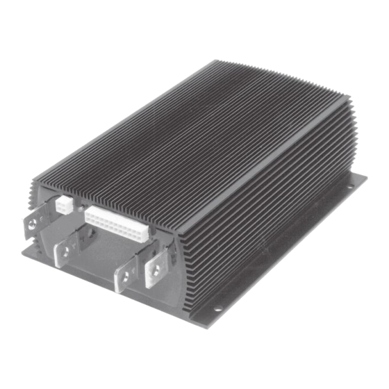
1 2 3 4 5 6 7 8 9 0 1 Specifications ........... B-1 APPENDIX B 1 2 3 4 5 6 7 8 9 0 1 1 2 3 4 5 6 7 8 9 0 1 Curtis 1214-/15-/19-8 Manual... - Page 3 FIGURES / TABLES FIGURES . 1: Curtis 1215-8 motor controller ........1 . 2: Mounting dimensions, Curtis 1214-/15-/19-8 controller ......... 3 . 3: Standard wiring diagram ..........6 . 4: Wiring for 5kΩ–0 throttle (“Type 1”) ......8 . 5: Wiring for 20kΩ...
-
Page 4: Overview
A2 (plug diode to motor armature) B+ (positive battery) Like all Curtis motor controllers, the 1214-/15-/19-8 controller offers superior operator control of the vehicle’s motor drive speed. Features include: Power MOSFET design, providing • infinitely variable drive and plug brake control •... - Page 5 Power connections made by tin-plated solid copper busses, with a polarized Molex connector for control signals Familiarity with your Curtis controller will help you install and operate it properly. We encourage you to read this manual carefully. If you have questions, please contact the Curtis office nearest you.
-
Page 6: Installation And Wiring
7.1 (0.28) dia., 4 plcs 5 .5 (0 .22 ) [6 plcs in 1219] 26.4 × 20.6 × 2.3 (1.04 × 0.81 × 0.09); 8.4 (0.33) dia. hole thru 81.3 (3.2) 3.18 (0.125) Dimensions in millimeters and (inches) Curtis 1214-/15-/19-8 Manual... -
Page 7: Connections: Low Current
Pin 19 Pin 20 Pin 21 Pin 22 Pin 23 emergency reverse (BB) check output [optional] Pin 24 A 4-pin low power connector, also located on the front of the controller, is provided for the handheld programmer. Curtis 1214-/15-/19-8 Manual... -
Page 8: Connections: High Current
Wear safety glasses, and use properly insulated tools to prevent shorts. — Charging or discharging generates hydrogen LEAD ACID BATTERIES gas, which can build up in and around the batteries. Follow the battery manufacturer’s safety recommendations. Wear safety glasses. Curtis 1214-/15-/19-8 Manual... -
Page 9: Wiring: Standard Configuration
Standard Fig. 3 SWITCHES SWITCHES wiring diagram, CONTACTORS MODE EMERG. BRAKE/ KEYSWITCH FORWARD REVERSE MAIN Curtis 1214-/15-/19-8 SEAT SELECT controller. 5kΩ–0 THROTTLE (TYPICAL) POLARITY PROTECTION DIODE POWER FUSE MAIN CONTACTOR PRECHARGE RESISTOR (250 Ω, 5 W) Curtis 1214-/15-/19-8 Manual... - Page 10 MODE FORWARD KEYSWITCH SELECT EMERGENCY REVERSE BRAKE REVERSE (walkies only) SEAT SWITCH The throttle shown in Figure 3 is a 5kΩ–0 type. Various other throttles can also be accommodated, and are discussed in the throttle wiring section. Curtis 1214-/15-/19-8 Manual...
-
Page 11: Wiring: Throttle
Wiring for various throttles is described below. These include 5kΩ–0 and 0–5kΩ throttles, 0–5V and 0–10V throttles, 3-wire potentiometer throttles, and elec- tronic throttles. If the throttle you are planning to use is not covered, contact the Curtis office nearest you. Ω –0 Throttle (“Type 1”) The 5kΩ–0 throttle (called a “Type 1”... -
Page 12: Fig. 6 Wiring For 0-5K Ω Throttle ("Type 3")
5V or 10V. Pot Low (Pin 14) is the current return path for all Type 2 throttles. It is 200 mV above B- and must have at least 0.1 mA flowing into it to prevent pot faults. Curtis 1214-/15-/19-8 Manual... -
Page 13: Fig. 7 Wiring For 0-5V Throttle ("Type 2")
10 mA. If the 0–10V throttle input (Pin 5) exceeds 16 volts, the controller output will be disabled. : In Figure 8(a), NOTE the throttle’s voltage input signal is in reference to Pot Low. Curtis 1214-/15-/19-8 Manual... -
Page 14: Fig. 8 Wiring For 0-10V Throttle ("Type 2")
Pot Low pin. If the Pot Low input current falls below 0.1 mA, a throttle fault is generated and the controller is disabled. : The Pot Low pin (Pin 14) must not be tied to ground. NOTE Curtis 1214-/15-/19-8 Manual... -
Page 15: Wiring: Emergency Reverse Check
2 — INSTALLATION & WIRING Curtis ET-XXX Electronic Throttle The Curtis ET-XXX provides throttle and forward/reverse inputs; wiring is shown in Figure 10. Wiring for Curtis Fig. 10 ET-XXX electronic throttle (“Type 2”). WHT/ KEYSWITCH WHT/BRN GREEN ORANGE BLACK BLACK/WHITE PIN KEY 0–5V Input... -
Page 16: Contactors, Switches, And Other Hardware
To protect the control wiring from accidental shorts, a low current fuse (appropriate for the maximum current draw) should be connected in series with the battery feed. These devices are both shown in the wiring diagrams. Curtis 1214-/15-/19-8 Manual... -
Page 17: Installation Checkout
LED diagnostic code in Section 5 (Diagnostics and Troubleshooting). When the problem has been corrected, it may be necessary to cycle the brake/seat switch in order to clear the fault code. Curtis 1214-/15-/19-8 Manual... - Page 18 The vehicle should be limited to 15% speed and a fault indicated. If you used a programmer, disconnect it when you have completed the checkout procedure. Curtis 1214-/15-/19-8 Manual...
-
Page 19: Programming And Adjustment
Any inadvertent changing of parameters can be “undone” using this procedure— even if you can’t remember what the previous settings were—as long as the programmer has not been unplugged and power has not been removed from the controller. Curtis 1214-/15-/19-8 Manual... -
Page 20: Maintenance
4 — MAINTENANCE MAINTENANCE There are no user-serviceable parts inside Curtis controllers. No attempt should be made to open the controller. Opening the controller may damage it and will void the warranty. However, it is recommended that the controller exterior be cleaned periodi- cally, and—if a handheld programmer is available—this periodic cleaning pro-... -
Page 21: Testing The Fault Detection Circuitry
4. Leave the keyswitch on and remove the inline fuse wire. The vehicle status should continue to remain off. 5. Cycle the keyswitch off and on, release the brake, and apply the throttle. The vehicle should now operate normally. Curtis 1214-/15-/19-8 Manual... -
Page 22: Diagnostics And Troubleshooting
If the programmer shows the forward switch closing and the vehicle now drives normally, the problem has been corrected. Refer to the troubleshooting chart (Table 1) for suggestions covering a wide range of possible faults. Curtis 1214-/15-/19-8 Manual... -
Page 23: Troubleshooting Chart
>60 volts (36–48V models). 2. Vehicle operating with charger attached. over-/under-temp. cutback 1. Temperature >85°C or <-25°C. THERMA L CUT B ACK 2. Excessive load on vehicle. 3. Improper mounting of controller. 4. Operation in extreme environments. Curtis 1214-/15-/19-8 Manual... -
Page 24: Led Diagnostics
: Only one fault is indicated at a time, and faults are not queued up. NOTE Operational faults—such as a fault in SRO sequencing—are cleared by cycling the brake/seat switch or keyswitch. (See “Fault recovery” in Appendix A for more information.) Curtis 1214-/15-/19-8 Manual... -
Page 25: Programmer Menus
Neutral brake current limit N E U T B R A K E C / L Neutral brake: on or off N E U T R A L B R A K E (Notes are on the next page.) Curtis 1214-/15-/19-8 Manual... - Page 26 T E M P ° C Minimum temperature seen * M I N T E M P Maximum/minimum temperatures recorded while controller active. After controller power is cycled, the initially recorded temperatures will be accurate only to within 10°C. Curtis 1214-/15-/19-8 Manual...
- Page 27 F A U L T 1 Throttle low input fault T H R O T T L E F A U L T 2 * <16 volts (24–36V models); <21 volts (36–48V models) † >46 volts (24–36V models); >60 volts (36–48V models) Curtis 1214-/15-/19-8 Manual...
-
Page 28: Appendix A Glossary Of Features And Functions
The brake/seat switch must be closed for the controller to operate. This safety interlock is used on most material handling vehicles. Cycling the brake/seat switch or KSI clears most faults and enables opera- tion. Curtis 1214-/15-/19-8 Manual... - Page 29 This adjustment can be made electronically via the handheld programmer. Current limiting Curtis controllers limit the motor current to a preset maximum. This feature protects the controller from damage that might result if the current were limited only by motor demand. PWM output to the power section is reduced smoothly until the motor current falls below the set limit level.
- Page 30 APPENDIX A: FEATURES & FUNCTIONS controller were used. The current multiplication feature gives vehicles using Curtis controllers dramatically greater driving range per battery charge. Deceleration rate The deceleration rate is the time required for the controller to decrease from 100% duty factor to zero. The deceleration rate is fixed, and cannot be adjusted.
- Page 31 (all other faults) (cycle KSI or brake/seat switch) Curtis 1214-/15-/19-8 Manual...
- Page 32 The fault codes are listed in Table 2 (page 21). The fault code will continue to flash until the fault condition has been cleared during active fault detection. This will typically happen after cycling KSI for power-up fault condi- tions, and cycling the brake/seat switch for faults detected during operation. Curtis 1214-/15-/19-8 Manual...
- Page 33 (Plug current, however, is not reduced—in order to provide full vehicle braking under all thermal conditions.) The operating PWM frequency is shifted to 1.5 kHz when the controller is operating in the overtemperature range. Curtis 1214-/15-/19-8 Manual...
- Page 34 Pulse width modulation (PWM), also called “chopping,” is a technique that switches battery voltage to the motor on and off very quickly, thereby controlling the speed of the motor. Curtis 1200 series controllers use high frequency PWM—15 kHz—which permits silent, efficient operation.
- Page 35 Ramp shape output is always a percentage of that range. Ramp shapes with the creep speed setting raised to 10% are shown in Figure A-2. In Figure A-3, the creep speed is kept at 10% and the maximum speed setting dropped to 60%. Curtis 1214-/15-/19-8 Manual...
- Page 36 35% PWM output at half throttle (halfway between 10% and 60%). A 30% ramp shape gives 25% PWM at half throttle (30% of the range {which is 50%, from 10% to 60%}, starting at 10% output, or {[.30 x 50%] + 10%} = 25%). Curtis 1214-/15-/19-8 Manual...
- Page 37 PWM output at full throttle. The maximum speed settings in Mode 1 and in Mode 2 are independently adjustable via the handheld programmer. The maximum creep speed setting (see Creep speed) and the maximum emergency reverse speed setting (see Emergency reverse) are also adjustable via the handheld programmer. Curtis 1214-/15-/19-8 Manual A-10...
- Page 38 Full temperature compensation provides constant current limits throughout the normal operating range (heatsink temperatures of -25°C to +85°C). The tem- perature sensor is also used to calculate and display the heatsink temperature on the handheld programmer. Temperature extreme current-limit cutback (see Overtemperature, Undertemperature) Curtis 1214-/15-/19-8 Manual A-11...
- Page 39 The 1214-/15-/19-8 controller accepts a variety of throttle inputs, through various combinations of its four throttle input pins. The most commonly used throttles (5kΩ–0 and 0–5kΩ pots, 3-wire pots, 0–5V, 0–10V, and the Curtis ET-XXX electronic throttle) can be hooked up simply by selecting the appropri- ate throttle type in the handheld programmer’s Program Menu.
- Page 40 If not reset, the internal timer times out and the microprocessor is “warm booted.” This causes the microprocessor to shut down its outputs (thus shutting down the controller) and attempt to restart. Curtis 1214-/15-/19-8 Manual A-13...
-
Page 41: Appendix B Specifications
1214S-8XXX 1215-8XXX 24–36 — <0.16 1215S-8XXX 24–36 — <0.14 1219-8XXX 24–36 — <0.12 1219S-8XXX 24–36 — <0.10 1219T-8XXX 24–36 800* — <0.08 1214-8XXX 36–48 — <0.30 1215-8XXX 36–48 — <0.20 1219-8XXX 36–48 — <0.15 30-second rating Curtis 1214-/15-/19-8 Manual A-14...
Need help?
Do you have a question about the MultiMode 1214-8 and is the answer not in the manual?
Questions and answers