Pego ECP202 EXPERT + BASE Series Use And Maintenance Manual
Hide thumbs
Also See for ECP202 EXPERT + BASE Series:
- Use and maintenance manual (25 pages) ,
- Quick manual (32 pages) ,
- Use and maintenance manual (28 pages)

Subscribe to Our Youtube Channel
Related Manuals for Pego ECP202 EXPERT + BASE Series


Summary of Contents for Pego ECP202 EXPERT + BASE Series
- Page 1 ECP202 EXPERT + BASE Use and maintenance manual READ AND KEEP Rel. Software: 26 ELECTRICAL BOARDS FOR REFRIGERATING INSTALLATIONS REV. 01-20...
- Page 2 ECP202 EXPERT + BASE...
-
Page 3: Table Of Contents
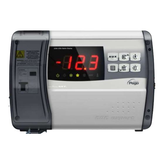
ECP202 EXPERT + BASE CONTENTS INTRODUCTION CHAP. 1 Page 4 Generality Page 4 Product ID codes Page 5 Overall dimensions Page 5 Identification data INSTALLATION CHAP. 2 Page 6 Important information for the installer Page 6 Standard assembly kit Page 7 Installing the unit FUNCTIONS CHAP. - Page 4 ECP202 EXPERT + BASE CHAPTER 1: INTRODUCTION GENERAL The electronic controllers of the ECP202 EXPERT + BASE series have been designed to control static or ventilated cold rooms. The ECP202 EXPERT + BASE electronic board allows the user to control all the components on a refrigeration unit such as compressor, evaporator fans, defrosting elements and cold room light.
- Page 5 CHAP. 1 - Introduction ECP202 EXPERT + BASE OVERALL DIMENSIONS IDENTIFICATION DATA The unit described in this manual has an ID plate on the side showing all the relevant identification data: • Name of Manufacturer • Code of the panel •...
- Page 6 CHAP. 2 - Installation ECP202 EXPERT + BASE CHAPTER 2: INSTALLATION IMPORTANT INFORMATION FOR THE INSTALLER 1. Install the device in places where the protection rating is observed and try not to damage the box when drilling holes for wire/pipe seats. 2.
- Page 7 CHAP. 2 - Installation ECP202 EXPERT + BASE INSTALLING THE UNIT Fig. 1: Raise the transparent cover that shields the magneto-thermal cut-out switch and remove the screw cover on the right-hand side. Fig. 2: Undo the 4 fixing screws at the front of the box.
- Page 8 CHAP. 2 - Installation ECP202 EXPERT + BASE Fig. 6: Use the three existing holes to fix the box back panel to the wall: use three screws of a length suitable for the thickness of the wall to which the panel will be attached.
- Page 9 CHAP. 3 - Functions ECP202 EXPERT + BASE CHAPTER 3: FUNCTIONS ECP202 EXPERT + BASE PANEL FUNCTIONS Cold room temperature displaying and regulation with decimal point. Evaporator temperature with decimal point displaying from parameter. Plant control activation/deactivation. Plant alarms signaling (probe error, minimum and maximum temperature alarm, compressor protection, door alarm).
-
Page 10: Technical Characteristics
CHAP. 4 - Technical characteristics ECP202 EXPERT + BASE CHAPTER 4: TECHNICAL CHARACTERISTICS TECHNICAL CHARACTERISTICS Power supply 230 V~ 10% 50/60Hz Voltage Max power (only electronics) ~ 7 VA Rated current (with all loads connected) Cold room conditions Working temperature -5T40°C <90% R.H. -
Page 11: Warranty Terms
The intervention service in warranty can be refused when the equipment is modified or transformed. Under no circumstances Pego S.r.l. will be liable for any loss of data and information, costs of goods or substitute services, damage to property, people or animals, loss of sales... -
Page 12: Control Panel
CHAP. 5 – Parameter programming ECP202 EXPERT + BASE CHAPTER 5: PARAMETER PROGRAMMING CONTROL PANEL FRONT KEYPAD AUXILIARY RELAY CONTROL (controls the relays manual if parameter AU1/AU2 = 2/-2) ... -
Page 13: Led Display
CHAP. 5 - Parameter programming ECP202 EXPERT + BASE DOWN / MANUAL DEFROST ROOM LIGHT LED DISPLAY Cold room temperature / parameters Stand-by (flashes on stand-by. Outputs are deactivated) Room light (flashes if door switch activated) ... -
Page 14: General
CHAP. 5 – Parameter programming ECP202 EXPERT + BASE GENERAL To enhance safety and simplify the operator’s work, the ECP202 EXPERT + BASE system has two programming levels; the first level (Level 1) is used to configure the frequently modified SETPOINT parameters. The second programming level (Level 2) is for general parameter programming of the various controller work modes. -
Page 15: Level 1 Programming
CHAP. 5 - Parameter programming ECP202 EXPERT + BASE LEVEL 1 PROGRAMMING (User level) To gain access to the Level 1 configuration menu proceed as follows: 1. Press the () and () keys simultaneously and keep them pressed for a few seconds until the first programming variable appears on the display. -
Page 16: Level 2 Programming
CHAP. 5 - Data programming ECP202 EXPERT + BASE LEVEL 2 PROGRAMMING (Installer level) To access the second programming level, proceed as follows: 1. Press the UP () and DOWN () keys and the LIGHT key simultaneously for a few seconds. When the first programming variable appears the system automatically goes to stand-by. - Page 17 CHAP. 5 - Parameter programming ECP202 EXPERT + BASE 0 = current temperature Display viewing during Defrost 1 = temperature at the start of the defrost 2 = “DEF” Net address for connection to TeleNET 0 ÷ 31 (with SEr=0) supervision system or Modbus 1 ÷...
- Page 18 CHAP. 5 - Parameter programming ECP202 EXPERT + BASE -6 (NC) = relay de-energised during stand-by -5 (NC) = Contact for casing element control (AUX relay closed with compressor output inactive). -4 (NC) = pump down function (NC, see CHAP 5.16) -3 (NC) = automatic auxiliary relay managed by StA temp.
-
Page 19: Switching On The Ecp202 Expert + Base Electronic Controller
CHAP. 5 – Parameter programming ECP202 EXPERT + BASE 0 = Cold function 1 = Hot function Thermostat functioning mode (in this mode defrosting and fan disable Fst are excluded) 0 = only display set point 1 = display set point, AUX, light access Password type of protection 2 = access in programming not permitted (active when PA is not equal 0) -
Page 20: Defrost With Heater And Temperature Control
CHAP. 5 - Parameter programming ECP202 EXPERT + BASE DEFROST WITH HEATER AND TEMPERATURE CONTROL 5.14 Set the parameter d1=2 for the management of heater defrost by time with temperature control. During the defrost the output is activated when the evaporator’s temperatures are lower than d2. -
Page 21: Telenet Monitoring / Supervision System
Base Series / ECP Expert Series rel. 25 or higher". NET CONFIGURATION WITH MODBUS-RTU PROTOCOL For RS485 connections with Modbus-RTU protocol follow the scheme below. Refer to MODBUS-RTU_ECP202EXP user manual (available on Pego Internet web site) for MODBUS-RTU communication protocol specification. USE AND MAINTENANCE MANUAL Page 21 Rev. -
Page 22: Troubleshooting
CHAP. 7 - Troubleshooting ECP202 EXPERT + BASE CHAPTER 7: TROUBLESHOOTING TROUBLESHOOTING In the event of any anomalies the ECP202 EXPERT + BASE in case of anomalies, it notifies the operator by means of the alarm codes displayed on the display and an audible signal emitted by a buzzer inside the control panel. -
Page 23: Eu Declaration Of Conformity
THIS DECLARATION OF CONFORMITY IS ISSUED UNDER THE EXCLUSIVE RESPONSIBILITY OF THE MANUFACTURER: PEGO S.r.l. a socio unico - Via Piacentina 6/b, 45030 Occhiobello (RO) – Italy – Società soggetta all’attività di direzione e coordinamento di Castel S.r.l. DENOMINAZIONE DEL PRODOTTO IN OGGETTO / DENOMINATION OF THE PRODUCT IN OBJECT MOD.:... -
Page 24: Ecp202 Expert + Base Wiring Diagram
Appendices ECP202 EXPERT + BASE ECP202 EXPERT + BASE WIRING DIAGRAM USE AND MAINTENANCE MANUAL Page 24 Rev. 01-20... -
Page 25: Connection Example (1) - Ecp202 Expert + Base
Appendices ECP202 EXPERT + BASE CONNECTION EXAMPLE (1) - ECP202 EXPERT + BASE Connection with outputs powered for direct control of functions. USE AND MAINTENANCE MANUAL Page 25 Rev. 01-20... - Page 26 Appendices ECP202 EXPERT + BASE CONNECTION EXAMPLE (2) - ECP200 EXPERT + BASE Mixed connection with on/off contact to enable towards condensing unit power board and fan, light and defrost outputs powered for direct control. USE AND MAINTENANCE MANUAL Page 26 Rev.
- Page 27 ECP202 EXPERT + BASE USE AND MAINTENANCE MANUAL Page 27 Rev. 01-20...
- Page 28 Tel. +39 0425 762906 Fax +39 0425 762905 e-mail: info@pego.it – www.pego.it AFTER-SALES ASSISTANCE SERVICE Tel. +39 0425 762906 e-mail: tecnico@pego.it Distributor: USE AND MAINTENANCE MANUAL Page 28 Rev. 01-20 PEGO s.r.l. reserves the right to make amendments to this user manual at any moment.
Need help?
Do you have a question about the ECP202 EXPERT + BASE Series and is the answer not in the manual?
Questions and answers