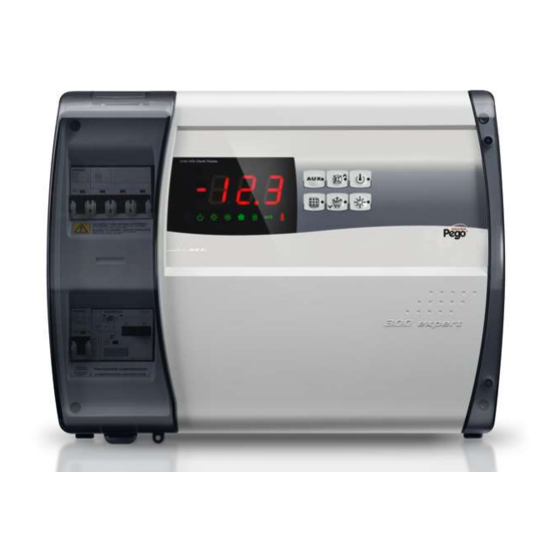
Pego ECP300 EXPERT Use And Maintenance Manual
Hide thumbs
Also See for ECP300 EXPERT:
- Use and maintenance manual (45 pages) ,
- Operation and maintenance manual (48 pages)

Related Manuals for Pego ECP300 EXPERT


Summary of Contents for Pego ECP300 EXPERT
- Page 1 ECP300 EXPERT Use and maintenance manual READ AND KEEP Rel. Software: 26 REL. 01-21 ELECTRICAL BOARDS FOR REFRIGERATING INSTALLATIONS...
- Page 2 ECP300 EXPERT Thanks for choosing this PEGO electrical panel. This manual gives detailed information on installation, use and maintenance of ECP300 EXPERT series electrical panels and special version. Our products are designed and built in compliance with current standards, on the specific field of refrigeration and conditioning systems.
-
Page 3: Table Of Contents
Pag. 20 Compressor motor circuit breaker calibration Pag. 21 Closing the electrical panel FUNCTIONALITY CHAP. 4 Pag. 22 Functions managed by the ECP300 EXPERT electrical panel DATA PROGRAMMING CHAP. 5 Pag. 23 Control panel Pag. 23 Front keypad Pag. 24 LED Display Pag. - Page 4 Complete management of three-phase refrigerating systems up to 7,5HP static or ventilated, with off-cycle or electrical defrosting. ECP300 EXPERT U VD Line of power and control panels dedicated to the management of a three-phase evaporating unit only, where this unit is served by a refrigeration plant or a remote condensing unit.
-
Page 5: Technical Characteristics
CHAP. 2 - Technical characteristics ECP300 EXPERT CHAPTER 2: TECHNICAL CHARACTERISTICS PRODUCT ID CODES (*) Code available on request Line of electrical panel of ECP300 EXPERT VD 4 series: SIEMENS COMPONENTS PEGO identification codes Compressor motor circuit breaker range 110300EVD401 (*) - Page 6 Pump-down / Thermostat Pump-down / Thermostat selection OUTPUTS See motor circuit breaker thermal range See motor circuit breaker thermal range Compressor relative to PEGO panel ID code relative to PEGO panel ID code Condenser fans output 1 800W (1ph) 800W total (1ph)
- Page 7 CHAP. 2 - Technical characteristics ECP300 EXPERT ECP300 EXPERT U VD 6 ECP300 EXPERT U VD 12 TECHNICAL CHARACTERISTICS Box dimensions 400x300x135 mm 400x300x135 mm Weight 9 Kg 10 Kg Protection rating IP65 IP65 Power supply (3F+N+T) 400Vac ±10% 50/60Hz 400Vac ±10% 50/60Hz...
- Page 8 CHAP. 2 - Technical characteristics ECP300 EXPERT OVERALL DIMENSIONS USE AND MAINTENANCE MANUAL Page 8 Rel. 01-21...
-
Page 9: Identification Data
CHAP. 2 - Technical characteristics ECP300 EXPERT IDENTIFICATION DATA The device described in this manual is provided on the side of a tag showing its identification data: • Manufacturer's Name • Code of the electrical panel • Serial number (S.N.) •... -
Page 10: Transport And Storage
CHAP. 2 - Technical characteristics ECP300 EXPERT TRANSPORT AND STORAGE Each electrical panel is supplied packed to be shipped without being damaged under normal conditions of transport. In the case of subsequent transport, it must be verified that: there are no objects or free parts inside the panel. -
Page 11: Warranty Conditions
The intervention service in warranty can be refused when the equipment is modified or transformed. Under no circumstances Pego S.r.l. will be liable for any loss of data and information, costs of goods or substitute services, damage to property, people or animals, loss of sales or earnings,... -
Page 12: Standard Equipment For Assembly And Use
CHAPTER 3: INSTALLATION STANDARD EQUIPMENT FOR ASSEMBLY AND USE The ECP300 EXPERT electrical panel, for assembly and use, is equipped with: • Nr 4 sealing gaskets, to be placed between the fixing screw and the back of the box. • Nr 1 use and maintenance manual. - Page 13 CHAP. 3 - Installation ECP300 EXPERT Fig. 1: Lift the transparent protection cover general magneto-thermal switch. Fig. 2: Remove the screw cover on the right side. Fig. 3: Unscrew the 4 fixing screws of the front panel. USE AND MAINTENANCE MANUAL Page 13 Rel.
- Page 14 CHAP. 3 - Installation ECP300 EXPERT Fig. 4: Close the transparent protection cover of the general magneto- thermal switch. Fig. 5: Open the front of the panel by lifting it up and sliding the two black hinges up to the end of the stroke.
- Page 15 CHAP. 3 - Installation ECP300 EXPERT Fig. 7: Apply pressure on the sides of each individual hinge to remove it from seat and completely remove the front panel. Fig. 8: Using a screwdriver, press the four pre-set holes on the back to make...
- Page 16 CHAP. 3 - Installation ECP300 EXPERT Fig.10: Using four holes made previously, fix the back of the box using four screws of adequate length in relation to the thickness of the wall. Place a rubber washer (supplied) between each fastening screw and the back of the box.
-
Page 17: Electrical Wirings
CHAP. 3 - Installation ECP300 EXPERT ELECTRICAL WIRINGS For electrical connections, refer to the specific wiring diagram and to the ❑ technical characteristics of the panel model to be installed. The power supply to the panel must be carried out exclusively with a ❑... -
Page 18: Connection Of The Front Panel
CHAP. 3 - Installation ECP300 EXPERT CONNECTION OF THE FRONT PANEL Re-hook the front panel and reconnect the connector of the electronic board as indicated below. Fig.12: Re-hook the front panel at the back of the box by reinserting the two black hinges in the appropriate seats. -
Page 19: Pre-Use Checks
CHAP. 3 - Installation ECP300 EXPERT PRE-USE CHECKS After having carried out the wiring, check the correct execution of the ❑ same by means of the wiring diagram. Make sure that the screws on the clamps are properly tightened. ❑... -
Page 20: Compressor Motor Circuit Breaker Calibration
CHAP. 3 - Installation ECP300 EXPERT COMPRESSOR MOTOR CIRCUIT BREAKER CALIBRATION Below we show step by step how to correctly calibrate motor circuit breaker dedicated to the compressor. Fig.15: When the system is started for first time it’s suggested to calibrate the... -
Page 21: Closing The Electrical Panel
CHAP. 3 - Installation ECP300 EXPERT CLOSING THE ELECTRICAL PANEL Once the electrical connections, checks and calibrations have been completed, the electrical panel can be closed. Fig.18: Close the front panel, making sure that all cables are inside the box and that the box gasket is correctly housed. -
Page 22: Functions Managed By The Ecp300 Expert Electrical Panel
CHAP. 4 - Functionality ECP300 EXPERT CHAPTER 4: FUNCTIONALITY FUNCTIONS MANAGED BY THE ECP300 EXPERT ELECTRICAL PANEL Signalling with LED icons of the plant status. Electronic control with wide LED display and easy-to-use keyboard. Display and regulation of the cell temperature with decimal point. -
Page 23: Control Panel
CHAP. 5 - Data programming ECP300 EXPERT CHAPTER 5: DATA PROGRAMMING CONTROL PANEL FRONT KEYPAD AUXILIARY RELAY CONTROL (it manually controls the auxiliary relays, if parameter AU1/AU2 = 2/-2) ... -
Page 24: Led Display
CHAP. 5 - Data programming ECP300 EXPERT LED DISPLAY AMBIENT TEMPERATURE VALUE / SETTINGS STANDBY ICON Led OFF = Electrical panel OFF Led ON = Electrical panel ON and in regulation Led flashing = Electrical panel in stand-by (outputs are disabled) DOOR SWITCH / ROOM LIGHT ICON ... -
Page 25: Generality
ECP300 EXPERT GENERALITY For safety reasons and greater practicality for the operator, the ECP300 EXPERT system provides two levels of programming; the first one for the simple configuration of the frequently editable SETPOINT parameters, the second one for the programming and the setting of the general parameters related to the various operating modes of the board. -
Page 26: Level 1 Programming (User Level)
CHAP. 5 - Data programming ECP300 EXPERT LEVEL 1 PROGRAMMING (User Level) To access the first level configuration menu it is necessary to: 1. Press the () and () keys simultaneously and keep pressed for more than 3 seconds until the first programming variable appears on the display. -
Page 27: Level 2 Programming (Installer Level)
CHAP. 5 - Data programming ECP300 EXPERT LEVEL 2 PROGRAMMING (Installer Level) To access the first level configuration menu it is necessary to: 1. Press the UP (), DOWN () and LIGHT keys simultaneously and keep pressed for more than 3 seconds. - Page 28 CHAP. 5 - Data programming ECP300 EXPERT Smart defrost setpoint (if dSE=1) The count of the time between defrosts is increased only if the compressor is on and -30 ÷ 30 °C 1°C the evaporator temperature is lower than dSt.
- Page 29 CHAP. 5 - Data programming ECP300 EXPERT -6 (NC) = relay de-energized in stand-by -5 (NC) = Contact for crankcase heater control (AUX relay closed with compressor output not active). -4 (NC) = pump down function (see chap. 5.16) -3 (NC) = automatic auxiliary relay managed by the StA temperature set with 2°C...
-
Page 30: Hot/Cold Activation/Deactivation Conditions
If the Pump-down function is selected (Parameter AU1/AU2 = 4 / -4) refer to Chapter 5.16 for compressor on / off conditions. In hot mode (mOd=1), the ECP300 EXPERT controller activates the hot output (COMPR output) when the room temperature drops below the set value minus the differential (r0); it switches off the hot output (COMPR output) when the room temperature is higher than the set value set. -
Page 31: Defrost With Thermostated Resistances
HOT GAS DEFROST 5.15 Warning: do not set d1 = 1 in this type of electrical panel. For systems with hot gas defrost there is a dedicated line of ECP300 EXPERT electrical panels with pre-fitted wiring. PUMP DOWN FUNCTION 5.16 Selection of PUMP DOWN functioning mode for the compressor working on X1 terminal block, changing the selection connection as indicated in the wiring diagram. -
Page 32: Telenet Monitoring / Supervision System
NET CONFIGURATION WITH MODBUS-RTU PROTOCOL To connect the panel in an RS485 network with Modbus-RTU protocol, follow the diagram below. Refer to MODBUS-RTU_ECP202EXP user manual (available on Pego Internet web site) for MODBUS-RTU communication protocol specification. USE AND MAINTENANCE MANUAL Page 32 Rel. -
Page 33: Diagnostics By Means Of Alarm Codes
CHAPTER 7: DIAGNOSTICS DIAGNOSTICS BY MEANS OF ALARM CODES In case of anomaly, the ECP300 EXPERT controller will alert the operator through the alarm codes displayed on the screen and with an acoustic signal emitted by a buzzer. The EL and EH temperature alarms remain visible even after they have returned (alarm icon on steady) until they are acquired by pressing the mute key. -
Page 34: Troubleshooting
CHAP. 7 - Diagnostics ECP300 EXPERT TROUBLESHOOTING If there is not an alarm code, we list below some of the most common causes that can cause anomalies. These causes can be due to problems internal or external to the electrical panel. -
Page 35: General Safety Rules
CHAP. 8 - Maintenance ECP300 EXPERT CHAPTER 8: MAINTENANCE GENERAL SAFETY RULES Whatever the nature of the maintenance, it must be performed exclusively by specialized technical personnel. In the event of a fault or maintenance to the electrical system, before proceeding with any checks, the panel must be disconnected from the mains power switch in the open position (O). -
Page 36: Spare Parts
Terminal block Wires tightening After first 20 days of functioning Terminal block Wires tightening Annual SPARE PARTS ECP300 EXPERT panels spare parts PEGO Identification Codes DESCRIPTION 200SCHBASE4 Spare part electronic card Spare protection cover of the general magneto-thermal switch COP300EXP and screw covers Spare parts must be requested to your distributor. - Page 37 THIS DECLARATION OF CONFORMITY IS ISSUED UNDER THE EXCLUSIVE RESPONSIBILITY OF THE MANUFACTURER: PEGO S.r.l. a socio unico - Via Piacentina 6/b, 45030 Occhiobello (RO) – Italy – Società soggetta all’attività di direzione e coordinamento di Castel S.r.l. DENOMINAZIONE DEL PRODOTTO IN OGGETTO / DENOMINATION OF THE PRODUCT IN OBJECT ...
- Page 38 Attachments / Appendices ECP300 EXPERT DIAGRAM CONNECTION TO THE TELENET NETWORK Remember to assign a network address that is consistent with the current TeleNET network, if any (2nd level parameter Ad) USE AND MAINTENANCE MANUAL Page 38 Rel. 01-21...
-
Page 39: Part List
Attachments / Appendices ECP300 EXPERT PART LIST LEGEND RIF. DESCRIPTION Box rear in ABS 4 poles magnetothermic circuit breaker with general switch / general protection function Contactors for units control Compressor protection motor circuit breaker Auxiliary protection 1-pole magnetothermic circuit breaker... - Page 40 Tel. +39 0425 762906 E-mail: info@pego.it – www.pego.it AFTER-SALES ASSISTANCE CENTRE Tel. +39 0425 762906 E-mail: tecnico@pego.it Distributor: USE AND MAINTENANCE MANUAL PEGO s.r.l. reserves the right to make amendments to this user manual at any moment. Page 40 Rel. 01-21...
Need help?
Do you have a question about the ECP300 EXPERT and is the answer not in the manual?
Questions and answers