Pego ECP202 EXPERT Use And Maintenance Manual
Hide thumbs
Also See for ECP202 EXPERT:
- Quick manual (32 pages) ,
- Use and maintenance manual (28 pages) ,
- Use and maintenance manual (28 pages)

Related Manuals for Pego ECP202 EXPERT


Summary of Contents for Pego ECP202 EXPERT
- Page 1 ECP202 EXPERT Use and maintenance manual READ AND KEEP Rel. Software: 26 REV. 01-19 ELECTRICAL BOARDS FOR REFRIGERATING INSTALLATIONS...
- Page 2 List of Level 1 variables Pag. 14 Level 2 programming Pag. 14 5.10 List of Level 2 variables Pag. 17 5.11 Switching on the ECP202 EXPERT electronic controller Pag. 17 5.12 Hot /cold activation/deactivation conditions Pag. 17 5.13 Manual defrosting Pag. 18 5.14...
-
Page 3: Pag.
CHAPTER 1: INTRODUCTION GENERAL DESCRIPTION: The ECP202 EXPERT is a new control panel for cold rooms with a single-phase compressor up to 2HP, specially designed to provide the user with safety, protection, control and ease of installation. It allows the user to control all the components on a refrigerating system: compressor, evaporator fans, defrosting elements, room light and thermostat-holder demisting element. -
Page 4: Pag.
CHAP. 1 - Introduction ECP202 EXPERT PRODUCT ID CODES 200202EXPCS Controls and manages compressor, defrosting elements, evaporator fans and room light. 2 Aux configurable relays Differential magnetothermic circuit breaker 16A Id=300 mA (Id=30 mA on request) OVERALL DIMENSIONS Dimensions (mm) -
Page 5: Important Information For The Installer
STANDARD ASSEMBLY KIT For the purposes of assembly and use, the electronic ECP202 EXPERT control unit comes with: • N° 3 seals, to be fitted between the fixing screws and the box back panel;... -
Page 6: Pag.
CHAP. 2 - Installation ECP202 EXPERT INSTALLING THE UNIT Fig. 1: Raise the transparent cover that shields the magneto-thermal cut-out switch and remove the screw cover on the right-hand side. Fig. 2: Undo the 4 fixing screws at the front of the box. - Page 7 Install short-circuit overload safety devices on all the power cables connected to the ECP202 EXPERT so as to prevent damage to the device. Work and/or maintenance must ONLY be carried out on the unit after disconnecting the panel from the power supply and from any inductive/power loads: doing so allows the worker to do his job safely.
-
Page 8: Technical Characteristics
CHAP. 3 - Technical characteristics ECP202 EXPERT CHAPTER 3: TECHNICAL CHARACTERISTICS TECHNICAL CHARACTERISTICS Power supply 230 V~ 10% 50/60Hz Voltage Max power (only electronics) ~ 7 VA Rated current (with all loads connected) Climatic conditions Working temperature -5 ÷ +50°C Storage temperature -10 ÷... -
Page 9: Warranty
The intervention service in warranty can be refused when the equipment is modified or transformed. Under no circumstances Pego S.r.l. will be liable for any loss of data and information, costs of goods or substitute services, damage to property, people or animals, loss of sales... -
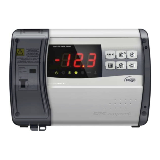
Page 10: Control Panel
CHAP. 5 - Parameter programming ECP202 EXPERT CHAPTER 5: PARAMETER PROGRAMMING CONTROL PANEL FRONT KEYPAD AUXILIARY RELAY CONTROL (controls the relays manual if parameter AU1/AU2 = 2/-2) ... - Page 11 CHAP. 5 - Parameter programming ECP202 EXPERT DOWN / MANUAL DEFROST ROOM LIGHT LED DISPLAY Cold room temperature / parameters Stand-by (flashes on stand-by. Outputs are deactivated) Room light (flashes if door switch activated) ...
- Page 12 ECP202 EXPERT GENERAL To enhance safety and simplify the operator’s work, the ECP202 EXPERT has two programming levels; the first level (Level 1) is used to configure the frequently-modified SETPOINT parameters. The second programming level (Level 2) is for general parameter programming of the various controller work modes.
- Page 13 CHAP. 5 - Parameter programming ECP202 EXPERT LEVEL 1 PROGRAMMING (User level) To gain access to the Level 1 configuration menu proceed as follows: 1. Press the () and () keys simultaneously and keep them pressed for a few seconds until the first programming variable appears on the display.
- Page 14 CHAP. 5 - Parameter programming ECP202 EXPERT LEVEL 2 PROGRAMMING (Installer level) To access the second programming level press the UP () and DOWN () keys and the LIGHT key simultaneously for a few seconds. When the first programming variable appears the system automatically goes to stand-by.
- Page 15 ECP202 EXPERT Net address for connection to TeleNET 0 ÷ 31 (con SEr=0) supervision system or Modbus 1 ÷ 247 (con SEr=1) 0 = TeleNET protocol RS-485 communication protocol 1 = Modbus-RTU protocol 0 = 300 baud 3 = 2400 baud...
- Page 16 ECP202 EXPERT -6 (NC) = relay de-energised during stand-by -5 (NC) = Contact for casing element control (AUX relay closed with compressor output inactive). -4 (NC) = pump down function (NC, see CHAP 5.16) -3 (NC) = automatic auxiliary relay managed by StA temp.
- Page 17 If Pump-Down function is selected (Parameter AU1/AU2 = 4/-4), see chapter 5.16 for compressor activation/deactivation conditions. In hot mode (mOd=1), the ECP202 EXPERT controller activates the heat output (COMPR output) when cold room temperature drops below setting-differential (r0); it deactivates the heat output (COMPR output) when cold room temperature is higher than the setting.
- Page 18 CHAP. 5 - Parameter programming ECP202 EXPERT DEFROST WITH HEATER AND TEMPERATURE CONTROL 5.14 Set the parameter d1=2 for the management of heater defrost by time with temperature control. During the defrost the output is activated when the evaporator’s temperatures are lower than d2.
-
Page 19: Telenet Monitoring / Supervision System
CHAP. 6 - Optional kit ECP202 EXPERT CHAPTER 6: OPTIONAL KIT TeleNET MONITORING/SUPERVISION SYSTEM For TeleNET connections follow the scheme below. Refer to TeleNET user manual for instrument configuration. WARNING: During configuration, at entry “Module” to select the entry "Instrument ECP Base Series / ECP Expert Series rel. -
Page 20: Troubleshooting
CHAPTER 7: TROUBLESHOOTING TROUBLESHOOTING In the event of any anomalies the ECP202 EXPERT n case of anomalies, it notifies the operator by means of the alarm codes displayed on the display and an audible signal emitted by a buzzer inside the control panel. The EL and EH temperature alarms remain visible even after their return (alarm icon lights on) until their acquisition (by pressing the key tacit). - Page 21 THIS DECLARATION OF CONFORMITY IS ISSUED UNDER THE EXCLUSIVE RESPONSIBILITY OF THE MANUFACTURER: PEGO S.r.l. Via Piacentina 6/b, 45030 Occhiobello (RO) – Italy – Società soggetta all’attività di direzione e coordinamento di Castel S.r.l. DENOMINAZIONE DEL PRODOTTO IN OGGETTO / DENOMINATION OF THE PRODUCT IN OBJECT MOD.:...
- Page 22 Appendices ECP202 EXPERT ECP202 EXPERT WIRING DIAGRAM USE AND MAINTENANCE MANUAL Pag. 22 Rev. 01-19...
- Page 23 ECP202 EXPERT PART LIST REF. DESCRIPTION BOX REAR IN ABS BOX FRONT IN ABS FRONT COVER IN TRANSPARENT POLYCARBONATE BOX FRONT OPENING HINGE BOX CLOSURE SCREWS BOARD FIXING SCREWS MAGNETO-THERMAL CUT-OUT / POWER BREAKER CPU BOARD POLYCARBONATE SCREW COVER TERMINAL FOR EARTH CONNECTIONS USE AND MAINTENANCE MANUAL Pag.
- Page 24 Tel. +39 0425 762906 Fax +39 0425 762905 e.mail: info@pego.it – www.pego.it AFTER-SALES ASSISTANCE CENTRE Tel. +39 0425 762906 e.mail: tecnico@pego.it Distributor: USE AND MAINTENANCE MANUAL Pag. 24 PEGO s.r.l. reserves the right to make amendments to this user manual at any moment. Rev. 01-19...
Need help?
Do you have a question about the ECP202 EXPERT and is the answer not in the manual?
Questions and answers