Table of Contents
Advertisement
Quick Links
Advertisement
Table of Contents

Subscribe to Our Youtube Channel
Related Manuals for Kodak DryView 8150


Summary of Contents for Kodak DryView 8150
- Page 1 Kodak DryView 8150 Laser Imager User Guide...
- Page 2 Eastman Kodak Company 343 State Street Rochester, NY 14650 © Eastman Kodak Company, 2004 Kodak and DryView are trademarks of Eastman Kodak Company. 7F3319 Catalog number 1779545 Rev. A...
-
Page 3: Important Notice To Purchaser:
Customer. • Performance or non-performance of any third party equipment or software. • Impact of any Kodak product upon a network or third party equipment or software. • Malicious software infections caused by others. Virus Policy: In accordance with the HI Digital Solutions Virus Policy, document 3E4111, Kodak’s time to install patches and other changes to... -
Page 4: License
Quotation or Invoice, Eastman Kodak Company ("Kodak") grants to Customer a nonexclusive license to use one copy of the software on the equipment (the "Software"). Kodak represents that it has title to or has the right to license the Software. Customer agrees to use the Software only in... -
Page 5: Limited Warranty
Within thirty (30) days after any expiration or termination of this license, in whole or in part, the Customer agrees to deliver to Kodak all copies of the Software or media (whether in whole or in part) in the... -
Page 6: Limitation Of Remedies
Limitation of Remedies The remedies set forth above are Kodak's only obligation under the warranty. IN NO EVENT WILL KODAK OR ITS SUPPLIERS OR DEALERS BE LIABLE TO YOU FOR ANY INCIDENTAL OR CONSEQUENTIAL DAMAGES, INCLUDING ANY LOST REVENUES OR PROFITS, DOWNTIME COSTS, COST... -
Page 7: End-User License Agreement For Microsoft Desktop Operating Systems
State Street, Rochester, New York, 14650. END-USER LICENSE IMPORTANT-READ CAREFULLY: THIS END-USER LICENSE AGREEMENT AGREEMENT FOR ("EULA") IS A LEGAL AGREEMENT BETWEEN YOU (EITHER AN MICROSOFT DESKTOP INDIVIDUAL OR A SINGLE ENTITY) AND THE MANUFACTURER OPERATING SYSTEMS ("MANUFACTURER") OF THE COMPUTER SYSTEM OR COMPUTER SYSTEM COMPONENT ("HARDWARE") WITH WHICH YOU ACQUIRED THE MICROSOFT SOFTWARE PRODUCT(S) IDENTIFIED ABOVE ("SOFTWARE PRODUCT"... - Page 8 COMPUTER. – Storage/Network Use. The SOFTWARE PRODUCT may not be installed, accessed, displayed, run, shared or used concurrently on or from different computers, including a workstation, terminal or other digital electronic device ("Devices"). Notwithstanding the foregoing and except as otherwise provided below, any number of Devices, may access or otherwise utilize the file and print services and internet information services of the SOFTWARE PRODUCT, if included.
- Page 9 – Reservation of Rights. Manufacturer, MS and its suppliers (including Microsoft Corporation) reserve all rights not expressly granted to you in this EULA. 2. DESCRIPTION OF OTHER RIGHTS AND LIMITATIONS: – Windows 2000. If the SOFTWARE PRODUCT is Windows 2000, it may not be used by more than two (2) processors on the COMPUTER unless a higher number of processors is indicated on the Certificate of Authenticity that accompanies the SOFTWARE...
-
Page 10: Ranty
Manufacturer, MS or Microsoft Corporation which updates or supplements the original SOFTWARE PRODUCT is governed by this EULA unless alternative terms are provided with such updates or supplements. – Limitations on Reverse Engineering, Decompilation and Disassembly. You may not reverse engineer, decompile, or disassemble the SOFTWARE PRODUCT, except and only to the extent that such activity is expressly permitted by applicable law notwithstanding this limitation. - Page 11 with any trademarks or service marks of Manufacturer, MS or its suppliers (including Microsoft Corporation). – Application Sharing. The SOFTWARE PRODUCT may contain Microsoft NetMeeting, a product that enables applications to be shared between two or more computers, even if an application is installed on only one of the computers.
- Page 12 and treaties. This EULA grants you no rights to use such content. All rights not expressly granted under this EULA are reserved by MS and its suppliers (including Microsoft Corporation). 5. DUAL-MEDIA SOFTWARE PRODUCT. You may receive the SOFTWARE PRODUCT in more than one medium. Regardless of the type or size of medium you receive, you may use only one medium that is appropriate for the COMPUTER.
- Page 13 or re-export the SOFTWARE PRODUCT (or portions thereof): (i) to any country subject to a U.S. embargo or trade restriction; (ii) to any person or entity who you know or have reason to know will utilize the SOFTWARE PRODUCT (or portions thereof) in the design, development or production of nuclear, chemical or biological weapons;...
- Page 14 WARRANTY AND SPECIAL CONSUMER RIGHTS. CONSUMERS MAY HAVE THE BENEFIT OF CERTAIN PROVISIONS FOR RIGHTS OR REMEDIES PURSUANT TO THE TRADE PRACTICES ACT AND AUSTRALIA, NEW ZEALAND SIMILAR STATE AND TERRITORY LAWS IN AUSTRALIA OR THE CONSUMER OR PAPUA NEW GUINEA - GUARANTEES ACT IN NEW ZEALAND, IN RESPECT OF WHICH CERTAIN EXPRESS LIMITED LIABILITY MAY NOT BE EXCLUDED.
- Page 15 (OR RELATED COMPANY OF EITHER) TO ANY PERSON OR COMPANY ON ITS BEHALF IN RELATION TO THE PROFITABILITY OF OR ANY OTHER CONSEQUENCES OR BENEFITS TO BE OBTAINED FROM THE DELIVERY OR USE OF THE SOFTWARE AND ANY ACCOMPANYING MICROSOFT HARDWARE, SOFTWARE, MANUALS OR WRITTEN MATERIALS.
- Page 16 Manufacturer with a copy of your receipt. This Limited Warranty is void if failure of the SOFTWARE or hardware has resulted from accident, abuse, or misapplication. Any replacement SOFTWARE or hardware will be warranted for the remainder of the original warranty period or thirty (30) days, whichever is longer.
-
Page 17: Warranty And Special Provisions For Canada - Limited Warranty
WARRANTY AND SPECIAL LIMITED WARRANTY. Manufacturer warrants that (a) the SOFTWARE will PROVISIONS FOR CANADA - perform substantially in accordance with the accompanying written LIMITED WARRANTY materials for a period of ninety (90) days from the date of receipt, and (b) any Microsoft hardware accompanying the SOFTWARE will be free from defects in materials and workmanship under normal use and service for a period of one (1) year from the date of receipt. -
Page 18: Garantie Et Dispositions Particulières Pour Le Canada Garantie Limitée
AGREEMENT SHALL BE LIMITED TO THE AMOUNT ACTUALLY PAID BY YOU FOR THE SOFTWARE AND/OR MICROSOFT HARDWARE. BECAUSE SOME STATES/JURISDICTIONS DO NOT ALLOW THE EXCLUSION OR LIMITATION OF LIABILITY FOR CONSEQUENTIAL OR INCIDENTAL DAMAGES, THE ABOVE LIMITATION MAY NOT APPLY TO YOU. This Software License Agreement is governed by the laws of the Province of Ontario, Canada. -
Page 19: Limited Warranty
écrite et tout matériel qui l'accompagnent. Cette garantie limitée vous accorde des droits spécifiques reconnus par la loi. ABSENCE DE RESPONSABILITÉ POUR LES DOMMAGES INDIRECTS. Selon la portée maximale autorisée par la loi applicable, le Fabricant ou ses fournisseurs ne pourront être tenus responsables en aucune circonstance de tous dommages quels qu'ils soient (y compris mais non de façon limitative les dommages directs ou indirects causés par des lésions corporelles, la perte de bénéfices commerciaux, l'interruption des affaires,... - Page 20 misapplication. Any replacement SOFTWARE or hardware will be warranted for the remainder of the original warranty period or thirty (30) days, whichever is longer. NO OTHER WARRANTIES. TO THE MAXIMUM EXTENT PERMITTED BY APPLICABLE LAW, MANUFACTURER AND ITS SUPPLIERS DISCLAIM ALL OTHER WARRANTIES, EITHER EXPRESS OR IMPLIED, INCLUDING, BUT NOT LIMITED TO IMPLIED WARRANTIES OF MERCHANTABILITY AND FITNESS FOR A PARTICULAR PURPOSE, WITH REGARD TO THE SOFTWARE,...
- Page 21 expressly granted are reserved. If you acquired the SOFTWARE in the United States of America, this Software License Agreement and Warranty are governed by the laws of the State of Washington, U.S.A. If you acquired the SOFTWARE outside the United States of America, local law may apply.
- Page 22 Blank Page...
-
Page 23: Table Of Contents
Table of Contents Important Notice to Purchaser: ........................1-1 End User License Agreement (EULA)....................... 1-2 EASTMAN KODAK COMPANY Health Imaging Software End User License Agreement ......... 1-2 License............................... 1-2 Limited Warranty..........................1-3 Limitation of Remedies........................1-4 General .............................. 1-4 U.S. Government Restricted Rights ..................... 1-4 END-USER LICENSE AGREEMENT FOR MICROSOFT DESKTOP OPERATING SYSTEMS........ - Page 24 Table of Contents Home Screen ............................2-5 Screen Controls............................2-6 Local Panel Help ............................2-8 Local Panel Passcodes..........................2-9 Home Screen Description ........................2-10 Film Supply Button Status Information....................2-12 Home Screen Status Line ........................2-14 Home Screen Attention Notices......................2-15 Film Supply Screen..........................2-16 Density Test Screen...........................2-17 Main Menu..............................2-18 System Functions Screen........................2-20 Select job Queue Type Screen......................2-22 System Information Menu.........................2-26...
- Page 25 Displaying the Setup Local Panel Screen................... 2-60 Setting Time and Date............................ 2-64 Operator Maintenance........................... 2-67 Cleaning the Laser Imager ........................2-67 Replacing the Charcoal Filter ........................2-67 Preventive Maintenance .......................... 2-69 3 Troubleshooting Correcting Errors ............................3-1 Error and Alarm Indications ........................3-1 Home Screen Status Messages......................
- Page 26 Selecting Use of a Density Patch on the Film....................4-18 Selecting Color Negotiation ........................4-19 Setting up the Text (Annotation) Box ............................4-20 Saving the Modality (SCU) Parameters ..............................4-21 Backing up the Configuration ........................4-22 5 Optimizing Image Quality Image Quality Parameters..........................5-1 Selecting the Image Quality Parameter Values....................5-2 Non-GSDF Modalities ..........................5-2 GSDF-Compliant Modalities........................5-9 Entering the Image Quality Parameters ......................5-10...
-
Page 27: October
Dissipating Heat............................7-5 Glossary October 4, 2004 7F3319... -
Page 28: October
7F3319 October 4, 2004... -
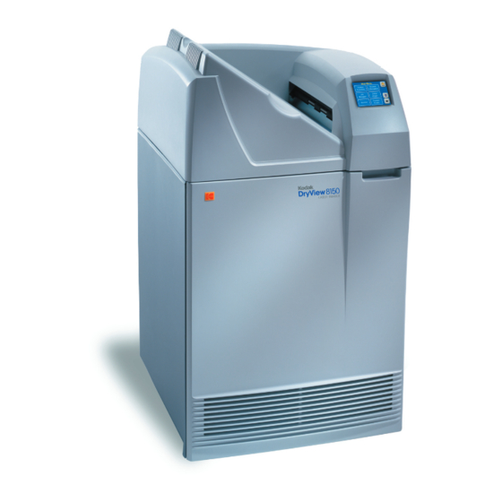
Page 29: Introduction
Introduction Kodak DryView 8150 Laser Imager The Kodak DryView 8150 Laser Imager is a continuous-tone laser imager with an internal photothermographic film processor. Heat, rather than photo chemicals, is used to develop the film. The Imager receives digital images from medical image source devices (modalities) over a network. - Page 30 Introduction H200_0036CAA 8150 Laser Imager 7F3319 October 4, 2004...
-
Page 31: How The Laser Imager Works
Image Source Devices Modality Network Modality Kodak DryView 8150 Laser Imager H200_0001ba Modality The Imager has hard-disk storage for a large number of digital images. As images arrive, they are stored on the hard disk and placed in a print queue (sequenced for printing) based on time of receipt and priority. -
Page 32: Print Sequence
Introduction During normal operation the Imager requires very little operator attention. The Imager prints automatically in response to print requests from the associated image devices. Information sent along with images by the modalities, such as film size, density and priority, control the print operations. - Page 33 Introduction Receive Tray Film Processor Drum Densitometer Transport Rollers Film Supply Cartridge Platen Rollers Suction Cups Platen Film Feed Rollers Exposure Module Laser Beam H200_0039DA 8100–49C Dashed line is the film path Print Sequence October 4, 2004 7F3319...
- Page 34 Blank Page...
-
Page 35: Operation And Maintenance
Operation and Maintenance Operator Control of the Imager During normal operation, the Kodak DryView 8150 Laser Imager receives and automatically prints images sent by modalities over a network. Very little operator control is required. The main operator responsibilities are: • Turn Imager power ON or OFF. -
Page 36: Turning Imager Power On And Off
Operation and Maintenance Turning Imager Power ON and OFF Power ON The power switch is located on the back of the Laser Imager. To turn ON the Imager, set the power switch to the " " position. The Imager performs a power-up self test that takes about five minutes. - Page 37 Operation and Maintenance 2. Touch Yes. The following 2 screens are displayed while the Imager is shutting down software. 3. Set the power switch to the " " (Off) position. October 4, 2004 7F3319...
-
Page 38: Power Failures
Operation and Maintenance Power Failures In the event of a power loss, the Laser Imager shuts down. Any films in process will not be completed. To restart the Imager after power is restored, turn OFF the power switch on the back of the Imager and then turn it ON. After warming up, the Imager automatically reprints any films that were in process when power was interrupted. -
Page 39: Using The Touch Screen Local Panel
Operation and Maintenance Using the Touch Screen Local Panel The Local Panel displays a collection of screens that you can use to monitor Imager operations and to control some Imager functions. You make menu selections and navigate between Local Panel screens by lightly touching buttons on the touch screen. -
Page 40: Screen Controls
Operation and Maintenance Screen Controls Many of the Local Panel screens have some or all of the buttons on the typical screen below. These buttons are used to navigate between the Local Panel screens and to select items from lists or menus. Screen Controls Home button. - Page 41 Operation and Maintenance List. Several types of lists appear in Local Panel screens. Examples are menus, lists of print jobs and lists of modalities. You select an item in a list using the Up and Down arrows and the Select button. Selecting an item displays another screen that presents information or choices related to the item you selected.
-
Page 42: Local Panel Help
Operation and Maintenance Local Panel Help The Local Panel has several types of Help information that explain most of the Local Panel functions. Touch the Help button to see a Help topic. Screen Help Most screens have a Help button that provides Help information for the screen and for buttons and other items on the screen Local Panel... -
Page 43: Local Panel Passcodes
Operation and Maintenance Local Panel Passcodes Some Local Panel functions can be performed only by users with passcodes. There are three types of Local Panel passcodes: Key Operator Lets Key Operators perform the following Passcode functions: • Delete print jobs •... -
Page 44: Home Screen Description
Operation and Maintenance Home Screen Description During the power-up self test, this is the first screen you see after the initial start-up screens. The Local Panel always returns to this screen after a few minutes if there are no operator selections on the touch screen. Title Bar. - Page 45 Operation and Maintenance Film Supply button. Touch to display the Film Supply screen which provides 3 choices: • Open Front Door • Calibrate Film • Run Density Test (See “Film Supply Screen” on page 2-16.) The Film Supply button also displays status information about the film supply within its outline.
-
Page 46: Film Supply Button Status Information
Operation and Maintenance Film Supply Button Status The Film Supply button displays information about the film supply with a Information combination of messages and color. The most common condition is: Type of Film Blue Background 14X17 Number of Sheets Film Size Remaining This indicates a normal film supply (20 sheets or more). - Page 47 Operation and Maintenance Film Supply Button Status Combinations Message in Background Explanation Film Supply Color Button Fail Flashing Blue The film cartridge has failed to and Yellow open. October 4, 2004 7F3319 2-13...
-
Page 48: Home Screen Status Line
Operation and Maintenance Home Screen Status Line The following messages can appear on the Status Line: Message Explanation Printing Printing images from the print queue. Ready Ready to print. No images in the print queue for the currently loaded film size. Self-test The Imager is performing the power-up self test. -
Page 49: Home Screen Attention Notices
Operation and Maintenance Home Screen Attention Three attention notices can appear on the Home Screen: Notices This notice appears when there are 1 or more print jobs in the print queue that require a different size or type of film than is currently loaded. An audible alarm sounds when the number of jobs waiting for media goes from 0 to 1. -
Page 50: Film Supply Screen
Operation and Maintenance Film Supply Screen This screen provides three options related to the film supply in the Imager. To display this screen: Home > touch Film Supply button. Open Front Unlatches the front door after closing the film cartridge and Door completing any films in the film path. -
Page 51: Density Test Screen
Operation and Maintenance Density Test Screen This screen lets you to print one or more SMPTE density test pattern images. You can specify the maximum density. To display this screen: Home > Film Supply button > Run Density Test Change Copies. Displays a keypad to change the number of copies of the test print. -
Page 52: Main Menu
Panel Passcodes” on page 2-57.) Refer to Section 4 for setup procedures to add a modality. Refer to the Kodak DryView 8150 Laser Imager Installation Guide for the required setup procedures. Current Errors button. Displays the Current Errors screen, which lists errors detected by the Imager. See “Current Errors... - Page 53 Operation and Maintenance Service button. Displays the Service screen. Provides several functions used by service technicians. • Most service functions require the Service passcode. (See “Local Panel Passcodes” on page 2-57.) • Refer to “Service Screen” on page 2-42 for information on this screen.
-
Page 54: System Functions Screen
Operation and Maintenance System Functions Screen This screen provides two functions: • Users who have logged on with a passcode can log off from this screen. • Operators can set the Imager either online or offline. When online, the Imager is connected to the network and can receive images from the associated modalities. - Page 55 Operation and Maintenance Printing enabled button. Toggles between Printing enabled and Printing disabled. When printing is disabled, the Imager can receive images from the modalities on the network but cannot print from the print queue. Requires Key Operator or Service passcode. Enabled/Disabled Indicator.
-
Page 56: Select Job Queue Type Screen
Operation and Maintenance Select job Queue Type This screen lists the three job queues and shows the number of print jobs in Screen each queue. To display this screen: Menu > Job Manager Queued to Print. This queue contains all print jobs waiting to be printed except jobs classified as “Unprintable”... - Page 57 Operation and Maintenance This screen shows the number of jobs in a queue from each modality. From Select Modality Screen this screen you can display a list of the jobs from any one modality. To display this screen: Menu > Job Manager > Queued to Print Name of the queue being displayed: •...
- Page 58 Operation and Maintenance This screen shows a list of the print jobs within a queue that are all from the Job List Screen same modality. The name of the source modality appears on the screen. To display this screen: Menu > Job Manager > Queued to Print > modality name Name of Queue Modality Name...
-
Page 59: Job Details
Operation and Maintenance This screen shows information about a single print job that you selected on Job Details Screen the previous screen. Users with a Key operator passcode can delete this job from the queue by touching the Delete button. To display this screen: Menu >... -
Page 60: System Information Menu
2-27. Versions Displays a screen that shows the versions of software components in the Imager. You may be asked to supply this information if you call Kodak for support. See “Versions Screen” on page 2-27. Print Counts Displays a screen that shows the number of films the Imager has printed and number of prints remaining before preventive maintenance is required. - Page 61 Operation and Maintenance This screen displays information that identifies the Imager and shows its System Information Screen network address. To display this screen: Menu > System Information >System Information This screen shows the current versions of software components in the Versions Screen Imager.
- Page 62 Operation and Maintenance This screen shows the number of films printed since the Imager was placed Print Counts Screen in service and the number of prints remaining before the next required PM (Preventative Maintenance session). To display this screen: Menu > System Information > Print Counts Print Counts The "Prints to PM"...
-
Page 63: Current Errors Screen
Operation and Maintenance Current Errors Screen This screen lists any errors detected by the software in the Imager during print operations. To display this screen: Menu > Current Errors Current Errors Error code - identifies the type of error. You will be asked for this code if you call for service. -
Page 64: Error Message Screen
Operation and Maintenance Error Message Screen This screen appears when the Imager detects an error. It provides information and recommended corrective action for a specific error. You can also display this screen by selecting an error listed on the Current Errors screen. -
Page 65: Setup Imager Screen
Operation and Maintenance Setup Imager Screen This screen is the entry point for all of the Imager configuration functions. These functions are used primarily for installation of the Imager, not for normal operation. Most of these functions require the Service passcode. A few of the Local Panel setup functions are accessible with a Key Operator passcode. - Page 66 Imager. The Service passcode is required to display this screen. For network setup procedures using this screen, refer to the Installation Manual for the Kodak DryView 8150 Laser Imager. To display this screen: Menu > Setup Imager > Network setup...
- Page 67 Operation and Maintenance This screen is used to edit the date and time displayed on the Local Panel Date and Time Screen Home screen. The Service passcode is required to access this screen. The date and time can be changed only within a plus or minus 24-hour window, just enough for time zone changes.
- Page 68 Operation and Maintenance Each of the modalities that has printed at least once to the Imager is listed Select Modality Screen on this screen. Selecting one of the modalities leads to a series of configuration screens that are used to enter and edit image quality parameters for the selected modality.
- Page 69 Operation and Maintenance From this screen you can access several other screens that allow you to Setup Local Panel Screen adjust some of the Local Panel properties. To display this screen: Menu > Setup Imager > Local Panel Calibrate touch accuracy - Displays a screen for setting the accuracy of the touch buttons on the Local Panel.
- Page 70 Operation and Maintenance From this screen you can enter the Service Telephone that appears on the Edit Service Telephone Number Screen System Information screen. Requires the Service passcode. To display this screen: Menu > Setup Imager > Edit Service tel. number 2-36 7F3319...
- Page 71 Operation and Maintenance Restore Configuration This menu choice allows you to restore the Imager configuration parameters from a previously-recorded backup file. The backup file is usually recorded on a floppy disk but can also be recorded on the Imager hard drive or on a remote network drive if accessible on the network.
- Page 72 Operation and Maintenance 6. Touch OK. 7. Enter the filename exactly as it is written on the backup disk and touch 2-38 7F3319 October 4, 2004...
- Page 73 Operation and Maintenance 8. Touch Yes. IMPORTANT: Do not touch OK yet. 9. Wait for the front door to open. The Imager first closes the film cartridge, completes any films in process and then unlatches the front door. October 4, 2004 7F3319 2-39...
- Page 74 Operation and Maintenance Front Door Computer Access Door H200_0034DAA 10. Open the computer access door. 11. Insert the backup diskette into the floppy disk drive. 12. Touch OK. The Imager reads in the backup file. This may take several minutes. 2-40 7F3319 October 4, 2004...
- Page 75 Operation and Maintenance 13. Touch OK. 14. Remove the backup disk from the computer. 15. Close the computer access door and the Imager front door. 16. Log out of the Service Passcode if you are done with service functions: a. Touch the Back arrow to return to the Main Menu. b.Touch System Functions.
-
Page 76: Service Screen
Operation and Maintenance Service Screen This screen is the access point for the Local Panel Service functions. To display this screen: Menu > Service PM. Enters the date that preventive maintenance is performed and also resets the print-to-PM counters to zero. See page 2-44. - Page 77 Operation and Maintenance Selecting Filter Change on the Service screen displays the screen below. Filter Change - Service Menu Choice Touch Yes to enter the current date into the Service History log as the date of a filter change. Selecting Ping on the Service screen tests the network connection between Ping - Service Menu Choice the Imager and any modality on the network.
- Page 78 Operation and Maintenance If the modality does not respond to the Ping, a message screen informs of the failure This menu choice performs two functions: Selecting PM on the Service PM (Preventive Maintenance)| Service Menu Choice Screen displays the screen below. •...
-
Page 79: Image Resizing
Operation and Maintenance When you enter the Customer First passcode and press OK, the PM date is entered and the "Prints to PM" counter is reset. A confirmation screen notifies you that the operation is complete. Image Resizing If the image sent from the modality is too large for the size of film in the Imager, the Imager can resize the image to fit on the film by either of two methods: •... - Page 80 Operation and Maintenance Image Resizing Methods Resizing Method Icon Printed on Film Minify Minify Icon The image file is reduced by the removal of pixel data If the Minify choice was selected when the Imager was setup, the Imager will minify an image if: Scale Icon 1.
- Page 81 Operation and Maintenance Image Resizing Methods Resizing Method Icon Printed on Film Crop (continued) Cropping allows “true size” printing for larger images. True size printing provides a common scale between images captured on analog systems (those which use medical x-ray film exposed by phosphor screens in cassettes) and printed digital images.
-
Page 82: Operation
Operation and Maintenance Operation Opening the Front Door During normal operation you may need to open the front door of the Imager to insert or remove the film cartridge, clear a film jam or change the charcoal filter. To open the front door while power is ON: 1. -
Page 83: Opening The Front Door Manually
Operation and Maintenance the front door will not unlatch. An error message appears to announce this error. The Error Message screen includes an Open Door button that will force the door open even though the film cartridge remains open. Opening the Front Door If the Imager power is OFF or if opening the front door from the Local Panel Manually fails, you can use the manual latch to open the front door. - Page 84 Operation and Maintenance 4. If the film cartridge is open, close the cover immediately. a. Clear any films that may be jammed in the cartridge area. b.Turn the rollback knob counterclockwise to close the cartridge. Rollback Knob Film Path (dashed line) H200_0004da Manually Closing the Film Cartridge 2-50...
-
Page 85: Opening The Hood
Operation and Maintenance Opening the Hood You will have to open the hood to clear film jams in the developer area or to open the front door manually. Output Tray Hood Support Grasp Hood Here CAUTION Whenever you raise or lower the hood, grasp the hood only in the area of the recessed slot below the Local Panel to avoid pinching your fingers. -
Page 86: Loading And Removing Film Cartridges
Operation and Maintenance Loading and Removing To load a film cartridge: Film Cartridges 1. Open the front door. (See “Opening the Front Door” on page 2-48.) 2. Insert the cartridge into the slot as shown in the illustration. 3. Slide the cartridge fully into the Imager. 4. -
Page 87: Recycling Empty Film Cartridges
Operation and Maintenance Recycling Empty Film In some regions you can return your empty Kodak DryView Film Cartridges Cartridges to Kodak for reuse and recycling. Contact your Kodak sales representative to determine the availability of the film cartridge recycling program in your region. -
Page 88: Requesting A Density Test
Operation and Maintenance 2. Touch Calibrate Film. 3. Touch Yes then OK. The Imager will print a calibration film before printing any jobs in the print queue that have not yet started printing and will interrupt a multi-sheet print job to run a calibration print. Requesting a Density Test The Imager can print an internally generated density test print with a SMPTE pattern. - Page 89 Operation and Maintenance 3. Touch Run Density Test. 4. If you want to change the maximum density value, highlight Change Max Density and touch Select. October 4, 2004 7F3319 2-55...
- Page 90 Operation and Maintenance 5. Enter the maximum density value that you want and touch OK. (Upper limit: 3.1.) The Density test screen reappears. 6. To print more than one copy, highlight Change copies and touch Select. 7. On the keypad, enter the number of copies and touch OK. 8.
-
Page 91: Local Panel Passcodes
Operation and Maintenance Local Panel Passcodes There are four levels of access to the Local Panel. Three of these access levels require passcodes. Passcode not required. Operator Level Operators can access most Local Panel features except for Service functions and Imager setup functions. -
Page 92: Setting Up Passcodes
Operation and Maintenance Setting Up Passcodes Key Operator Passcodes and the Service passcode are set up on the Passcode Entry screen. Each passcode must be accompanied by a User ID. Only a user with the Service passcode can enter Key Operator passcodes or change the Service passcode. -
Page 93: Logging Off
Operation and Maintenance Logging Off Users who have logged on with any passcode can log off by touching the Logoff button on the System Functions screen. There is also a passcode timeout feature that automatically logs a user off if the are no inputs on the touch screen for 2 minutes. -
Page 94: Adjusting Local Panel Preferences
Operation and Maintenance Adjusting Local Panel Key Operators can change the following Local Panel properties: Preferences • Volume of "beep" that sounds when you touch any button • Backlight intensity • Audible alarm volume • Audible alarm - enable or disable A Key Operator passcode is required to change these properties. - Page 95 Operation and Maintenance Set Up Local Panel Screen Adjust Touch Beep Duration To adjust beep duration: 1. On the Setup Local Panel screen, highlight Touch Beep Duration. 2. Touch Select. 3. Touch the Up or Down arrows to change duration of the beep sound. You will hear a beep each time you touch the Up or Down arrows.
- Page 96 Operation and Maintenance To increase or decrease the backlight intensity: Adjust Backlight Intensity 1. On the Setup Local Panel screen (page 2-61), highlight Backlight intensity. 2. Touch Select. 3. Touch the Up or Down arrows to change the intensity. 4. Touch the Back arrow to return to the Setup Local Panel screen. 2-62 7F3319 October 4, 2004...
- Page 97 Operation and Maintenance The audible alarm is a series of tone pulses that sound when an error Adjust the Audible Alarm occurs or when Waiting for Media appears on the Home screen. You can adjust the duration of the tone pulses. 1.
-
Page 98: Setting Time And Date
Operation and Maintenance Setting Time and Date The time and date appear in the Home screen. The time, time format, date and date format can be set. The Service Passcode is required. The combination of date and time can be increased or decreased by no more than 24 hours. - Page 99 Operation and Maintenance 4. Highlight Date and Time; then touch Select. 5. A keypad will prompt for the for the Service user name and then the Service passcode if you are not logged in. 6. To change the date format: a.
- Page 100 Operation and Maintenance 7. To change the date: a. Highlight Date and touch Select. A keypad appears on the Local Panel. b. Enter the new date and touch OK. The new date appears on the Date Time screen. 8. To change the time format: a.
-
Page 101: Operator Maintenance
Laser Imager. Isopropyl alcohol can dissolve the exterior paint on the Laser Imager. Replacing the Kodak DryView Laser Imaging Film emits a slight odor when it is heated during the Charcoal Filter developing process. A charcoal filter in the Imager absorbs and neutralizes this odor. - Page 102 Operation and Maintenance if the odor becomes noticeable or when "Preventive Maintenance" appears on the Home screen. CAUTION The charcoal filter is considered non-hazardous waste by the US EPA Resource Recovery Act. Under RCRA, you may dispose of filters in a landfill or incinerator with energy recovery in a municipal, commercial or industrial facility.
-
Page 103: Preventive Maintenance
Touch Filter Change and then Yes. The current date is entered into the log as the Filter Change Date. Preventive To maintain optimum performance from the Laser Imager, Kodak recommends that Maintenance preventive maintenance be performed periodically by an Authorized Service Provider of Kodak products. - Page 104 Operation and Maintenance Blank Page 2-70 7F3319 October 4, 2004...
-
Page 105: Troubleshooting
Occasionally errors (malfunctions), such as film jams, may occur in the imager during print operations. You can easily correct minor problems. If more serious malfunctions occur, you should contact a trained Authorized Service Provider of Kodak products (see “Calling for Support” on page 3-17). -
Page 106: Error Message Screen
Troubleshooting Error Message Screen The Error Message screen is the main error reporting mechanism for the Imager. When the Imager detects an error, an alarm sounds and the Local Panel displays an Error Message screen that describes the error and gives a corrective action. - Page 107 Troubleshooting NOTE: If you close an Error Message screen without correcting the current error, you can recall the Error Message from the Current Errors screen. (See “Current Errors Screen” on page 3-4.) When an error message is displayed: Operator Action 1.
-
Page 108: Current Errors Screen
Troubleshooting Current Errors Screen The Current Errors screen shows a list of uncorrected errors in the Imager. To display this screen: 1. Press the Menu button. 2. On the Main Menu screen, press Current Errors. The Current Errors screen appears: List of Errors Current Errors Screen To see detailed information about any of the errors:... -
Page 109: Current Errors Notice On The Home Screen
Troubleshooting Current Errors Notice on the When there are one or more uncorrected errors in the Imager, the Home Home Screen screen displays a Current Errors notice that shows the number of uncorrected errors in the Imager. To see a list of the current errors, you can display the Current Errors screen. -
Page 110: Calibration Failure
Troubleshooting Calibration Failure Periodically the Imager must be calibrated to ensure that internal settings match the characteristics of the film in the Imager. Calibration is performed by running a calibration print. The Imager runs a calibration print when: • A film cartridge containing film with new sensitometric characteristics (speed, contrast) is loaded. - Page 111 Troubleshooting These two calibration errors indicate a major machine or film fault. The Imager cannot continue to operate with the current film. If you cannot restore normal operation by following the recommended action on the error message screen, call for service. (See “Calling for Support”...
-
Page 112: Film Transport Problems
Troubleshooting Film Transport Problems The illustration below shows the path that film travels through the Imager after the operator requests a print. The numbers in the illustration identify key areas on the path through the five major areas in the Imager: Area 1 –... -
Page 113: Manually Closing The Film Cartridge
Troubleshooting Films may occasionally jam at various points along the film path. When a film jam or film feed error occurs, an error message appears. The error message identifies the area where a jam has occurred and recommends a corrective action. The following information supplements the advice given in the error messages for film feed problems. -
Page 114: Film Pickup Problems In Area 1
Troubleshooting 3. Clear any films that may be jammed in the film cartridge area. 4. Turn the rollback knob counterclockwise to close the cartridge. Film Pickup Problems in Area 1 Area 1 is the location where film is removed from the film cartridge and positioned to be sent by drive rollers toward the exposure area. -
Page 115: Removing Film Jams From Area 2
Troubleshooting Removing Film Jams from Area 2 Area 2 in the Imager includes the path between the film pickup assembly and the exposure platen. NOTE: When jams occur in Area 2, the film cartridge is left open. When you open the front door, the top sheets of film in the cartridge will be exposed. -
Page 116: Removing Film Jams From Area 3
Troubleshooting Removing Film Jams from Area 3 Area 3 includes the exposure platen. Jams in this area occur as film is entering the platen before exposure, or as film is leaving the platen after exposure. In rare cases, film may stall in the transport area above the platen. - Page 117 Troubleshooting b. Push the optics module toward the rear of the imager slowly and smoothly. Optics Module 10 cm (4 in.) c. Clear the film from inside the platen. If film is caught in the platen feed rollers, pull Plastic Thumb Tab 1 (inside the platen door) to the right.
-
Page 118: Removing Film Jams From Area 4
Troubleshooting Removing Film Jams from Area 4 Area 4 includes the film processor. When a jam occurs in this area all films in the Imager must be removed. Processor Drum Area 4 Plastic Thumb H200_0008da Jam Area 4 1. Open the hood. CAUTION Drum and rollers inside the processor are hot. - Page 119 Troubleshooting Open Drum Cover Open Clamps Plastic Thumb Opening the Drum Cover 3. Clear the jammed film from the processor area (there may be more than one sheet). If film is jammed in the drive rollers, pull the Plastic Thumb Tab to the left to open the rollers and free the film. 4.
-
Page 120: Removing Film Jams From Area 5
Troubleshooting Removing Film jams from Area 5 Area 5 consists of the components between the processor drum and the film exit tray. Jams can occur in this area between the drum and the densitometer, or in the densitometer. See the figure below. When a jam occurs in this area all films in the imager must be removed. -
Page 121: Calling For Support
Troubleshooting 3. Remove any films in the processor. (See page 3-14.) 4. Close the hood. 5. Open the front door. 6. Remove all films in the lower part of the Imager. 7. Close the front door. The processor will have to warm to operating temperature before the imager can resume printing. - Page 122 Troubleshooting Service Phone Numbers Country Phone Number Czech Republic 420 236 100 307 420 62 335 426 Denmark 45 70206129 Finland 35.88001214 France 01 4001 4705 Germany 49.0180.3000.307 India 1600 118989 Iran 00 98 216 950821 00 98 216 402105 00 98 21 256 9741 00 98 21 256 9097 Ireland...
- Page 123 Troubleshooting Service Phone Numbers Country Phone Number Romania 00 40 1210 3854 Saudi Arabia 00 966 2 682 8219 00 966 1 464 5064 Spain 902 19 03 99 Sweden 46.200.119.494 Switzerland 41.0800.804807 Syria 00 963 112128600 Tajikistan 00 90 216 578 2600 Turkey 90 216 572 54 33 Turkmenistan...
- Page 124 Blank Page...
-
Page 125: Adding A Modality
Adding a Modality After the Imager has been placed into service, you can later configure the Imager to print images from additional modalities. The Imager is capable of receiving images from twelve DICOM-compatible modalities concurrently. Adding a modality involves adjusting some of the image quality settings in the Imager to match the new modality. -
Page 126: Modality-Related Parameters
Adding a Modality Modality-Related Parameters The Imager must be configured to print from each connected modality. In the Imager a set of modality-specific parameters must be created for each modality that will print to the Imager. For many modalities, the required parameters can be taken from the "Modality Preferences Database"... -
Page 127: Configuration Procedure
Adding a Modality Configuration Procedure The modality setup procedure is performed on the Imager Local Panel. 1. Be sure that the proper film size and type required for the modality is loaded in the Imager. 2. Start from the Home screen. 3. - Page 128 Adding a Modality 5. Select Modality (SCU) config. 6. Enter the Service User ID (99) and the Service Passcode on the keypads that appear. Previously Configured Modalities NOTE: If the new modality has previously printed to the Imager but has not been configured, it will appear on the above list but without a footprint symbol.
- Page 129 Adding a Modality 8. Wait for the following message screen to appear - about 1 minute. (When a modality prints to the Imager for the first time, this message will appear.) NOTE: If this message does not appear, the modality may not be properly set up to print to the Imager.
- Page 130 Adding a Modality 10. Wait for the Imager to print the image sent from the modality. • The imager will attempt to find an appropriate set of parameters for the modality in its internal database of modality parameters. • If no parameter set is found for the modality, the Imager uses a universal set of parameters to print the test image.
- Page 131 Adding a Modality 14. Touch Yes. 15. Select the name of the modality manufacturer. October 4, 2004 7F3319...
- Page 132 Adding a Modality 16. Select the modality type. 17. Select Model. • The Imager searches the parameter database: – If an appropriate set of parameters is found, these parameters will be applied to all images printed from this modality. – If no parameter set is found for the modality, a universal set of image quality parameters is assigned to the modality.
- Page 133 Adding a Modality 18. Send another clinical image from the modality to the Imager. 19. Wait for the Imager to print. 20. Examine the quality of the print. 21. Is the quality of the test print acceptable? • Yes - Go to “Changing the Modality ID”...
-
Page 134: Changing The Modality Id
Adding a Modality c. Go to Section 5 of this manual to adjust the parameters shown on the Image Quality screen. d. After completing the procedure in Section 5, continue with “Changing the Modality ID”. Changing the Modality ID The Modality ID sent down from the modality is a combination of modality type and IP Address. -
Page 135: Setting The Advanced Parameters
Adding a Modality Setting the Advanced Parameters NOTE: The Imager automatically sets the Advanced default parameters for a modality when you begin the modality setup process. In most cases these settings are satisfactory. Do not change these parameters unless you are certain that your application of the modality requires different settings. -
Page 136: Selecting Film Size
Adding a Modality Selecting Film Size The film sizes accepted by the Imager are 14 by 17 in., 11 by 14 in., and 14 by 14 in. If the default size shown on the screen is not the desired size, change it. -
Page 137: Selecting Film Type
Selecting Film Type The Film Type choices are DVB (DryView Blue) and DVC (DryView Clear). There is more than one type of Kodak DryView DVB film. The DVB choice applies to all DVB and DVB+ film types. If the default shown is not correct for this modality, change the value as follows 1. -
Page 138: Selecting The Type Of Image Resizing
Adding a Modality Selecting the Type of If the image sent down from the modality is too large for the size of film Image Resizing installed in the Imager, the Imager can resize the image to fit on the film by either of two methods: •... -
Page 139: Selecting Print Priority
Adding a Modality 4. For most installations Override modality should be left at false. NOTE: If you select True for Override modality, the Image Resizing mode set in step will take precedence over any type of sizing requested by the modality. 5. - Page 140 Adding a Modality 3. Use the Select button to choose the desired priority for printing. 4. For most installations Override modality should be left at false. NOTE: If you select True for Override modality, the priority set in step will take precedence over any priority requested by the modality. 5.
-
Page 141: Selecting N_Event Reporting
Adding a Modality Selecting N_Event "N_Events" are status changes at the Imager, such as changes from "ready" Reporting to "busy." The Imager can be configured to report these status changes to the modality as they changes occur. CAUTION This feature can cause a serious malfunction in the modality if it is not designed or configured to accept N_Event messages. -
Page 142: Selecting Report Warnings
Adding a Modality Selecting Report "Warnings" are messages from the Imager indicating a non-fatal problem in Warnings the Imager. Like "N_Events," these can be sent to the modality if desired, but they should not be if they can cause problems at the modality. 1. -
Page 143: Selecting Color Negotiation
Adding a Modality Selecting Color The Imager prints only grayscale images. If a modality has color capability Negotiation and a request to print a color image is sent to the Imager, the Imager software can print a grayscale version of the color image. 1. -
Page 144: Setting Up The Text (Annotation) Box
Adding a Modality Setting up the Text (Annotation) Box This parameter allows you to select items to be printed in a "text box" on the bottom of each sheet of film. 1. Select Film Text to display the items you can select. 2. -
Page 145: Saving The Modality (Scu) Parameters
Adding a Modality Saving the Modality (SCU) Parameters 1. Select Save Changes to save the parameter changes you have made. 2. Touch OK. 3. Touch the Back arrow twice to return to the Setup Imager screen. October 4, 2004 7F3319 4-21... -
Page 146: Backing Up The Configuration
Adding a Modality Backing up the Configuration The configuration parameters must be backed up (recorded) on a floppy diskette so they can be restored if the Imager software is updated. You will need a blank 3.5-inch floppy diskette, 1.44 mb, IBM format. 1. - Page 147 Adding a Modality 4. Touch OK. 5. Choose an easy-to-remember file name for the backup file. For example, a:\09_15_04.bin or a:\backup1.bin. The prefix a:\ and suffix .bin are required. 6. Write down the filename. 7. Enter the filename on the keypad and touch OK on the keypad. October 4, 2004 7F3319 4-23...
- Page 148 Adding a Modality 8. Touch Yes. 9. Wait for the front door to open. 4-24 7F3319 October 4, 2004...
- Page 149 Adding a Modality The Imager first closes the film cartridge and then unlatches the door. This takes about 30 seconds. Front Door Computer Access Door H200_0034DAA 10. Open the computer access door. 11. Insert a blank diskette into the floppy disk drive. The Imager records a backup file of the configuration parameters on the diskette.
- Page 150 Adding a Modality 12. Touch OK. 13. Remove the floppy disk from the computer. 14. On the disk label, write the filename exactly as you entered in step 7. Include the date of the backup. 15. Store the floppy disk in a safe place. It may be required if the Imager is serviced.
- Page 151 Adding a Modality 18. Press the Back arrow. The Home screen should appear. Configuration of the new modality is now complete. October 4, 2004 7F3319 4-27...
- Page 152 Blank Page...
-
Page 153: Optimizing Image Quality
• Border density - The density of the border of the film. • TFT Set - A group of 15 Transfer Function Tables (TFTs) used in Kodak Imagers. Each TFT in the set is a grayscale curve that relates each digital input (pixel) value to a target value of perceived brightness and a corresponding target value of printed optical density. -
Page 154: Selecting The Image Quality Parameter Values
Optimizing Image Quality • Advanced - Includes two parameters: – Polarity - In general, indicates whether an image is black on a white background or the reverse. In this case, specifies whether the Imager will print images with the same polarity as the images sent from the modality (Positive), or the reverse (Negative). - Page 155 Optimizing Image Quality 4. Choose the Image Density associated with the Table No. you chose. If there is a range of density values: • Choose the density value indicated in bold if there is one. • If there is no bold value, choose the middle value. For example, if the range is 2.7 to 3.1, choose 2.9.
- Page 156 Table No. Image Smooth- Note (Contrast Density ing Type Setting)* (Dmax)* Kodak and other CR WRKSTN2A.w87 Select Table number (Computed Radiography) (contrast) and Dmax in and DR (Digital the pairs shown. Radiography) Systems. Do not use with Fuji Also Workstations and CR.(See Fuji CR below.)
- Page 157 Optimizing Image Quality Table 1. Selection of Parameters by Modality Type Modality Type TFT Set Table No. Image Smooth- Note (Contrast Density ing Type Setting)* (Dmax)* 6, 7, 9 2.9 - 3.1 DSA (Digital Subtraction VER713C0.w87 VER713C0 provides Radiography), including (Alternative 1) brighter image C-Arm and Digital Fluoro...
- Page 158 Optimizing Image Quality Table 1. Selection of Parameters by Modality Type Modality Type TFT Set Table No. Image Smooth- Note (Contrast Density ing Type Setting)* (Dmax)* 2.2, 2.3 VER713C0.w87 5 - 7 - 10 Table 7 is popular. Nuclear Medicine (Alternative 1) Table 5 has less mid-tone contrast and...
- Page 159 Optimizing Image Quality Table 1. Selection of Parameters by Modality Type Modality Type TFT Set Table No. Image Smooth- Note (Contrast Density ing Type Setting)* (Dmax)* 2.4 - 2.8 Ultrasound VER693C0.w87 5 - 8 - 12 Table number choices (Alternative 1) vary with manufacturer and radiologist.
- Page 160 Optimizing Image Quality Table 2. GSDF0 Dmax Setting versus Table Number (Contrast Setting) Density (Dmax) Table Number (Contrast) Density and Table Number must be chosen in the pairs shown. NOTE: Some DICOM GSDF-modalities may direct the use of DICOM Presentation Look Up Tables (PLUTs) for some or all images. If the PLUT capability in the 8150 Imager is enabled, a PLUT sent from the modality overrides the GSDF0 TFT set (used for GSDF modalities) and associated parameter settings.
-
Page 161: Gsdf-Compliant Modalities
Optimizing Image Quality GSDF-Compliant Use this procedure to select image quality parameters for GSDF-Compliant Modalities modalities that do not use PLUTs or use PLUTs for only some images. Write down the parameter values you select. a. Choose TFT Set GSDF0.w87 (used for all GSDF modalities). b. -
Page 162: Entering The Image Quality Parameters
Optimizing Image Quality Entering the Image Quality Parameters 1. After choosing the parameter values for the modality, enter them from the Image quality screen. • Each choice on this screen calls up an entry screen for one of the parameters. •... - Page 163 Optimizing Image Quality 3. Select Save changes to save the changes you have made, and touch 4. Send another image from the modality and check print quality. NOTE: For DICOM GSDF-compliant modalities, the printed images should approximately match images on DICOM GSDF-compliant displays. 5.
- Page 164 Optimizing Image Quality above the one you previously entered. 8. Enter and save the new Table number (steps - 3). 9. Send another image from the modality and check print quality again. NOTE: You may have to try other Table numbers (and Densities) to achieve high quality prints.
-
Page 165: Specifications
Specifications Dimensions Height: 117 cm (46 in.) - Top cover closed 158 cm (62.3 in.) - Top cover open Width: 63.5 cm (25 in.) Depth: 66 cm (26 in.) - Front door closed 124.5 cm (49 in.) - Front door open Weight: 204 kg (450 lb) Electrical... -
Page 166: Laser Specifications
Specifications Laser Specifications Wavelength: 805 - 815 nm Power: 50 mW Type Diode Diode Radiation Class: Imager Radiation Class Class 1 product Operating Environment Temperature: 15° to 35° C (59° to 95° F) Humidity: 15% to 85% RH, non condensing Magnetic Field: <... -
Page 167: Film Sizes
• Kodak DryView DVB+ Premium Laser Imaging Film NOTE: Not all of these film types are available in every country. Film Throughput Prints 70 films per hour. Agency Compliance See the Kodak DryView 8150 Laser Imager Safety Manual, document number 7F3779. October 4, 2004 7F3319... - Page 168 Blank Page...
-
Page 169: Film Technical Information
General Description This section describes the characteristics of Kodak DryView Laser Imaging Film, not the operation of the Kodak DryView 8150 Laser Imager. DryView Laser Imaging Film is a high-resolution, infrared-sensitive, photothermographic film designed specifically for the family of Kodak DryView Laser Imagers. -
Page 170: Image Quality
Because it is a totally dry imaging process, there is no image quality variability due to “wet” chemistry. Automatic Image Quality DryView Laser Imaging Film is system-matched for the Kodak patented Control Automatic Image Quality Control (AIQC) technology. This fully automated... -
Page 171: Recycling Film
However, the film does contain silver and polyester that may be recovered by using one of several recycling processes. Call your local Kodak sales representative or go to the Kodak web site www.kodak.com/go/KES Refer to Publication J700 and see “End of Life Management' section. -
Page 172: Handling Developed Film
Laser Imaging Film can be left on a light box for more than 24 hours. In extreme cases in which light boxes are exceptionally hot (120° F/49° C), Kodak recommends removing them prior to 8 hours of continuous exposure. Take care when using spotlight viewing for more than 30 seconds because temperatures near the light source may exceed 180°... - Page 173 Film Technical Information environment. To help maintain optimum performance, the filter requires periodic replacement. DryView Laser Imagers require no special venting. Dissipating Heat DryView Laser Imagers use controlled heat to develop DryView Laser Imaging Film. The heat has virtually no effect on the air temperature of the work area.
- Page 174 Blank Page...
- Page 175 Medical equipment that actually generates medical images (for example, an MRI). Magnetic Resonance. Not available or not applicable. K number The K number (Kodak number) is located on the Local Panel System Information Screen. Platen The metal surface on which the film rests as it is exposed. Shutdown The process of exiting current tasks and applications and turning the power off.
- Page 176 Test type The type of test film that will be printed. Two film test types are available: a density test film (SMPTE pattern) and a calibration film. Transfer Function Tables. Unprintable queue The queue of jobs that cannot be printed because of errors in the print jobs. Glossary-2 7F3319 October 4, 2004...
- Page 178 Eastman Kodak Company 343 State Street Rochester, NY 14650 Kodak and DryView are trademarks of Eastman Kodak Company. © Eastman Kodak Company, 2004...
Need help?
Do you have a question about the DryView 8150 and is the answer not in the manual?
Questions and answers