Table of Contents
Advertisement
Quick Links
Download this manual
See also:
User Manual
Advertisement
Table of Contents

Related Manuals for Mitsubishi Electric QD62


Summary of Contents for Mitsubishi Electric QD62
- Page 1 MITSUBISHI ELECTRIC MELSEC System Q Programmable Logic Controllers User’s Manual High-Speed Counter Module QD62, QD62E, QD62D, GX Configurator-CT (SW0D5C-QCTU-E) Art. no.: 130027 05 02 2003 INDUSTRIAL AUTOMATION MITSUBISHI ELECTRIC SH (NA)-080036-E Version E...
-
Page 2: Safety Precautions
• SAFETY PRECAUTIONS • (Always read before starting use.) Before using this product, please read this manual introduced in this manual carefully and pay full attention to safety to handle the product correctly. The instructions given in this manual are concerned with this product. For the safety instructions of the programmable controller system, please read the User's Manual for the CPU module to use. - Page 3 [INSTALLATION PRECAUTIONS] CAUTION • Use the PLC in an environment that meets the general specifications contained in the CPU User's Manual. Using this PLC in an environment outside the range of the general specifications may cause electric shock, fire, malfunction, and damage to or deterioration of the product. •...
- Page 4 [WIRING PRECAUTIONS] CAUTION • Always ground the shielded cable on the encoder side (relay box). Otherwise, malfunction may occur. • When wiring, be sure to verify the rated voltage of the product as well as the terminal layout. Fire or failure may result if incorrect voltage is input or incorrect wiring is performed. •...
-
Page 5: Revisions
This manual confers no industrial property rights or any rights of any other kind, nor does it confer any patent licenses. Mitsubishi Electric Corporation cannot be held responsible for any problems involving industrial property rights which may occur as a result of using the contents noted in this manual. -
Page 6: Table Of Contents
2- 1 to 2- 4 2.1 Applicable System ..........................2- 1 2.2 How to Check Software Version......................2- 3 2.3 About Use of the QD62 (E/D) with the Q00J/Q00/Q01CPU ..............2- 4 3 SPECIFICATIONS 3- 1 to 3-14 3.1 Performance Specifications ........................3- 1 3.2 Function List ............................ - Page 7 5 BASIC USAGE 5- 1 to 5-11 5.1 Understanding the Pulse Input and Counting Method................5- 1 5.1.1 Types of pulse input methods......................5- 1 5.1.2 Setting the count method ......................... 5- 3 5.1.3 Reading the present values ......................5- 3 5.2 Selecting the Counter Format.........................
- Page 8 9 TROUBLESHOOTING 9- 1 to 9- 2 9.1 Error Information ............................. 9- 1 9.2 The Count Operation is not Working...................... 9- 2 9.3 The Count Value is not Normal ......................9- 2 APPENDIX App- 1 to App- 2 Appendix 1 External Dimension Diagram ....................App- 1 Appendix 2 Difference Between A1SD62, A1SD62E and A1SD62D (S1) ..........App- 2 INDEX Index- 1 to Index- 2...
-
Page 9: Conformation To The Emc Directive And Low Voltage Instruction
About the Generic Terms and Abbreviations Unless otherwise specified, this manual uses the following generic terms and abbreviations to describe the Type QD62, QD62D and QD62E high-speed counter module. Generic Term/Abbreviation Description of the abbreviation/general terms ®... -
Page 10: Overview
Number of channels 2 channels The QD62(E/D) modules have the following input methods for 1 phase/2 phase pulse input: • Phase 1 pulse input multiple of 1 • Phase 1 pulse input multiple of 2 • CW/CCW • Phase 2 pulse input multiple of 1 • Phase 2 pulse input multiple of 2 •... -
Page 11: Features
The maximum speed of the QD62D can be changed by selecting from among 500 k, 200 k, 100 k and 10 k, while that of the QD62 and QD62E can be selected from among 200k, 100k and 10k. This allows an error-free count even with gradual rise/fall pulses. - Page 12 1 OVERVIEW MELSEC-Q (7) The preset function/counter selection function can be executed using an external control signal By applying voltage to the preset terminal/function start terminal of an external terminal, preset function/counter function selection can be executed. (8) Easy settings using the utility package A utility package is sold separately (GX Configurator-CT).
-
Page 13: System Configurations
(2) Mountable base unit QD62 (E/D) can be mounted on any of the base unit’s I/O slots ( 3). However, depending on combinations with other mounted modules and the number of mountings, there may be cases where the power capacity is insufficient. Be sure to consider the power capacity when mounting the module. - Page 14 2 SYSTEM CONFIGURATIONS MELSEC-Q (4) Software packages supported Correspondence between systems which use QD62 (E/D) and software packages are as shown below. The GX Developer is necessary when using a QD62 (E/D). Software Version GX Developer GX Configurator-CT Single PLC Version 1.10L or later...
-
Page 15: How To Check Software Version
2 SYSTEM CONFIGURATIONS MELSEC-Q 2.2 How to Check Software Version This section describes how to check the GX Configurator-CT software version. (1) How to check the GX Configurator-CT software version The GX Configurator-CT software version can be checked in GX Developer's "Product information"... -
Page 16: About Use Of The Qd62 (E/D) With The Q00J/Q00/Q01Cpu
Here, use of the QD62 (E/D) with the Q00J/Q00/Q01CPU is explained. (1) Number of QD62 (E/D) that can be installed when the Q00J/Q00/Q01CPU is used See Section 2.1 concerning the number of QD62 (E/D) that can be installed when the Q00J/Q00/Q01CPU is used. (2) Limitations when using the Q00J/Q00/Q01CPU (a) The coincidence detection interrupt function cannot be used. -
Page 17: Specifications
3 SPECIFICATIONS The following describes the performance specifications, I/O signals for the PLC CPU and buffer memory specifications of the QD62(E/D). For the general specifications of the QD62(E/D), see the User's Manual (hardware) for the CPU module used. 3.1 Performance Specifications... - Page 18 3 SPECIFICATIONS MELSEC-Q (2) QD62E (DC input sourcing output type) performance specifications Model name QD62E Item Counting speed switch settings 200 k (100 k to 200 kPPS) 100 k (10 k to 100 kPPS) 10 k (10 kPPS or less) I/O occupied points 16 points (I/O assignment: Intelligent 16 points) Number of channels...
- Page 19 3 SPECIFICATIONS MELSEC-Q (3) QD62D (differential input sinking output type) performance specifications Model name QD62D Item 500 k 200 k 100 k 10 k Counting speed switch settings (200 k to 500 kPPS) (100 k to 200 kPPS) (10 k to 100 kPPS) (10 kPPS or less) I/O occupied points 16 points (I/O assignment: Intelligent 16 points)
-
Page 20: Function List
3 SPECIFICATIONS MELSEC-Q 3.2 Function List The QD62(E/D) functions are listed below. Name Function Reference section Values from –2147483648 to 2147483647 can be counted. If the Linear counter function Section 5.2.1 count exceeds the range, this function detects an overflow. -
Page 21: I/O Signals For The Plc Cpu
The I/O signals for the QD62(E/D) PLC CPU are listed in the table below. For the I/O numbers (X/Y) and I/O addresses indicated in this and succeeding sections, it is assumed that the QD62(E/D) is mounted into I/O slot 0 of the standard base module. -
Page 22: Functions Of I/O Signals
3 SPECIFICATIONS MELSEC-Q 3.3.2 Functions of I/O signals The details of the I/O signals for the QD62(E/D) are listed in the table below. (1) Input signals Device No. Signal name Description QD62(E/D) PLC CPU Turns ON when the count preparation for QD62(E/D) is completed at the... - Page 23 (2) Output signals Device No. Signal name Operation timing Description PLC CPU QD62 (E/D) Coincidence signal No. 1 reset Turns ON when the counter value coincidence (point command No. 1) signal (X02/X09) is reset. Y09 Preset command Turns ON when the preset function is executed.
-
Page 24: Buffer Memory Assignments
3.4 Buffer Memory Assignments (1) Buffer memory assignment list Buffer memory assignments (without battery backup) for the QD62 (E/D) are listed in the table below. The initial values are set for the buffer memory when the power is turned on or the PLC CPU is reset. - Page 25 3 SPECIFICATIONS MELSEC-Q (2) Preset value setting (Buffer memory addresses CH1: 0 CH2: 20 to 21 • This area is used to set the values that are preset in the counter. • The setting range is from –2147483648 to 2147483647 (32-bit signed binary values).
- Page 26 3 SPECIFICATIONS MELSEC-Q (7) Sampling/periodic setting (Buffer memory addresses CH1: A CH2: 2A • This area is used to write the time setting values of the sampling counter function and periodic pulse counter function during counter function selection. • The setting range is from 1 to 65535 (16-bit binary values) and the time unit is 10[ms].
-
Page 27: Interface With External Devices
3 SPECIFICATIONS MELSEC-Q 3.5 Interface with External Devices The table below lists the external device interface for the QD62(E/D). (1) QD62 (DC input sinking output type) Terminal Input voltage Operating current number Internal circuit Signal name Operation classification (guaranteed value) (guaranteed value) 4.7k... - Page 28 3 SPECIFICATIONS MELSEC-Q (2) QD62E (DC input sourcing output type) Terminal Input voltage Operating current number Internal circuit Signal name Operation classification (guaranteed value) (guaranteed value) 4.7k When ON 21.6 to 26.4 V 2 to 5 mA 1/3W Phase A pulse input 24 V When OFF 5 V or less 0.1 mA or less...
- Page 29 3 SPECIFICATIONS MELSEC-Q (3) QD62D (Differential input sinking output type) Terminal Input voltage Operating current number Internal circuit Signal name Operation classification (guaranteed value) (guaranteed value) + 5V (DC/DC converter) Phase A pulse input 4.7k 1/16W 1/16W 1/2W Line driver level (Am26LS31 [manufactured by Texas Line Instruments] or equivalent) that conforms to RS-422-A in 4.7k...
-
Page 30: Encoders That Can Be Connected
3 SPECIFICATIONS MELSEC-Q 3.6 Encoders that can be Connected The encoders that can be connected to the QD62(E/D) are described below. (1) Encoders that can be connected to the QD62 and QD62E • Open collector output type encoders • CMOS level voltage output type encoders (Verify that the encoder output voltage meets the specifications for the QD62 and QD62E.) -
Page 31: Setup And Procedure Before Starting The Operation
4 SETUP AND PROCEDURE BEFORE STARTING THE OPERATION MELSEC-Q 4 SETUP AND PROCEDURE BEFORE STARTING THE OPERATION The following describes the procedure prior to the QD62(E/D) operation, the name and setting of each part of the QD62(E/D), and wiring method. 4.1 Handling Precautions The following are the precautions for handling the QD62(E/D). -
Page 32: Procedure Before Starting The Operation
The figure below shows the steps that should be followed before starting the QD62(E/D) operation. Start Module mounting Mount the QD62(E/D) in the specified slot. Wiring Wire external devices to the QD62(E/D). Intelligent function module switch setting Perform settings using the GX Developer (see Section 4.5) -
Page 33: Part Identification Nomenclature
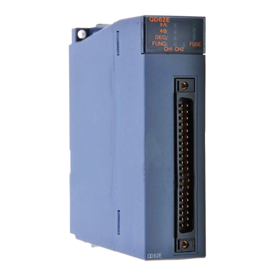
4 SETUP AND PROCEDURE BEFORE STARTING THE OPERATION MELSEC-Q 4.3 Part Identification Nomenclature The names of the parts used in the QD62(E/D) are shown below: QD62 φ A φ B DEC. FUNC. FUSE CH1 CH2 External wiring connector (40-pin connector) - Page 34 4 SETUP AND PROCEDURE BEFORE STARTING THE OPERATION MELSEC-Q (1) External wiring Connector The connectors for use with the QD62(E/D) should be purchased separately by the user. The connector types are listed below. (a) Connector types Type Model name Soldering type, straight out...
-
Page 35: Wiring
(2) For 1-phase input, always perform pulse input wiring on the Phase A side. (3) For the QD62(E/D), count will be performed if pulse status noise is input and a miscount will result. (4) Provide the following measures against noise for high-speed pulse input: (a) Always use a shielded twisted pair cable and provide grounding. -
Page 36: Wiring Example Of A Module And A Pulse Generator
The number inside the ( ) indicates the terminal number for channel 2. POINT When wiring the QD62, QD62E, and the encoder, separate the power supply cable and signal cable. The following diagram shows an example. [Wiring example] QD62(E) - Page 37 4 SETUP AND PROCEDURE BEFORE STARTING THE OPERATION MELSEC-Q (2) Wiring example with a voltage output type pulse generator (5 V DC) QD62,QD62E Pulse generator 24 V A20(A13) 12 V Phase A B20(B13) Twisted shield wire A19(A12) Shield ABCOM B19(B12)
-
Page 38: Wiring Example Of A Controller And An External Input Terminal
4 SETUP AND PROCEDURE BEFORE STARTING THE OPERATION MELSEC-Q 4.4.3 Wiring example of a controller and an external input terminal (1) When the controller (sink loading type) is 12 V DC QD62,QD62E Controller 24 V B17(B10) Twisted shield wire Preset... - Page 39 4 SETUP AND PROCEDURE BEFORE STARTING THE OPERATION MELSEC-Q (2) When the controller (source loading type) is 5 V DC QD62,QD62E Controller 24 V B17(B10) 12 V A16(A09) Preset Twisted shield wire B16(B09) Shield CTRLCOM A15(A08) 24 V B15(B08) 12 V...
- Page 40 4 SETUP AND PROCEDURE BEFORE STARTING THE OPERATION MELSEC-Q (3) When the controller is a line driver QD62D 24 V A18(A12) Controller 12 V B18(B12) Preset Twisted shield wire A17(A11) PRSTCOM B17(B11) Shield 24 V A16(A10) 12 V Function B16(B10) start Twisted shield wire A15(A09)
-
Page 41: Wiring Example With An External Output
When the coincidence output (EQU terminal) is used, an external power supply of 10.2 to 30 V DC will be required for operation of the internal photocopier. A wiring example is shown below. (1) For QD62, QD62D (Sink output type) QD62,QD62D EQU1... -
Page 42: Using The Connector/Terminal Block Converter Module
4 SETUP AND PROCEDURE BEFORE STARTING THE OPERATION MELSEC-Q 4.4.5 Using the connector/terminal block converter module (1) The figure below shows the wiring when a connector/terminal block converter module and a cable are used in the QD62 (E/D). QD62 φ A φ B DEC. - Page 43 (2) The following table lists the signal names and the corresponding connector side terminal numbers and terminal block side terminal symbols, when a connector/terminal block converter module is used in the QD62(E/D) . For the QD62 and QD62E For the QD62D...
-
Page 44: Switch Settings For The Intelligent Function Module
POINT The counting speed setting of 500kPPS can only be used with the QD62D. Setting the counting speed to 500k PPS for the QD62 and QD62E may cause miscounts. Thus, do not use this setting for the QD62 and QD62E. - Page 45 • Continue : PLC CPU continues the execution of the programs for modules other than those in which an error was detected. An intelligent function module error in the QD62(E/D) is detected when the Unit READY flag is not in the READY state due to a module hardware failure.
- Page 46 (3) Operating procedure Perform settings, starting with the GX Developer I/O assignment screen. (a) I/O assignment screen Specify the following for the slot where the QD62(E/D) is mounted. Type : Select "Intelli." Model name : Enter the module's model name.
-
Page 47: Basic Usage
5 BASIC USAGE MELSEC-Q 5 BASIC USAGE This section explains the basic usage of the QD62 (E/D). 5.1 Understanding the Pulse Input and Counting Method 5.1.1 Types of pulse input methods Six types of the pulse input methods are available. These include 1 phase multiple of 1, 1 phase multiple of 2, CW/CCW pulse input, 2 phase multiple of 1, 2 phase multiple of 2, and 2 phase multiple of 4. - Page 48 For phase 1 pulse input, either a multiple of 1 or multiple of 2 count method can be selected. The relationship between the phase A pulse input and the down count command is shown below. QD62(E/D) Pulse input φ A Encoder Down count command φ...
-
Page 49: Setting The Count Method
5 BASIC USAGE MELSEC-Q 5.1.2 Setting the count method The count method is set using the GX Developer intelligent function module. See Section 4.5 for details on the setting method. 5.1.3 Reading the present values This section explains the methods of reading the present values stored in the buffer memory or the count values when counter function selection is executed. -
Page 50: Selecting The Counter Format
5 BASIC USAGE MELSEC-Q 5.2 Selecting the Counter Format Select either linear counter or ring counter with the GX Developer intelligent function module. See Section 4.5 for details on the setting method. 5.2.1 Selecting the linear counter (1) Linear counter operation When the linear counter is selected, the count operation is performed between –2147483648 (minimum value) and +2147483637 (maximum value). -
Page 51: Selecting The Ring Counter
5 BASIC USAGE MELSEC-Q 5.2.2 Selecting the ring counter (1) Ring counter operation When the ring counter is selected, the count operation is performed repeatedly between the ring counter minimum value (addresses CH1: 14 to 15 , CH2: 34 to 35 ) and maximum value (addresses CH1: 16 to 17 , CH2: 36... - Page 52 5 BASIC USAGE MELSEC-Q (a) The ring counter will operate as follows when the "present value < ring counter minimum value" or "ring counter maximum value < present value". • For up count Even if the present value reaches the ring counter minimum value, the ring counter minimum value will be retained as is.
-
Page 53: Using The Coincidence Output Function
5 BASIC USAGE MELSEC-Q 5.3 Using the Coincidence Output Function The coincidence output function presets any count value, compares it with the present counter value, and outputs a signal when they match. For the coincidence output, 2 points can be set for each channel. To use the coincidence signal external output, turn ON the coincidence signal enable command {Y02(Y0A)}. - Page 54 (a) With the MELSEC-Q series intelligent function module, each module can have up to 16 points of interruption factors (SI). The QD62 (E/D) has 4 points of interrupt factors corresponding to the coincidence outputs shown below. SI No.
- Page 55 "Interrupt (SI) No.". Setting range: 0 to 15 The following example shows SI 0 to 3 of the QD62(E/D) installed in the slot where the start I/O is 20 being assigned to interrupt pointers I50 to I53.
-
Page 56: Using The Preset Function
(Addresses 0 to 1 to 21 )) for the QD62 (E/D). At the start (OFF to ON) of the preset command, the preset value in the preset value setting buffer memory is preset in the present value storage buffer memory. - Page 57 (Addresses 0 to 1 to 21 )) for the QD62(E/D). At the start (OFF to ON) of the preset command (voltage applied to the preset input terminal), the preset value in the preset value setting buffer memory is preset in the present value storage buffer memory.
-
Page 58: Convenient Usage
6 CONVENIENT USAGE MELSEC-Q 6 CONVENIENT USAGE 6.1 Selecting the Counter Function By selecting the counter function with the counter function selection setting, the disable count function, latch counter function, sampling counter function and periodic pulse counter function can be used. The counter function selection can be executed by writing the data shown in the table below into the counter function selection setting buffer memory (address 9 )} and... -
Page 59: Reading The Counter Function Selection Count Value
6 CONVENIENT USAGE MELSEC-Q 6.1.1 Reading the counter function selection count value The counter function selection count values are stored when the counter function selection is executed. The count values when the latch counter, sampling counter and periodic pulse counter functions are executed are stored in the counter function selection count value storage buffer memory at the addresses shown in the table below. -
Page 60: Count Error
6 CONVENIENT USAGE MELSEC-Q 6.1.2 Count error With the counter function selection, an error occurs in the count when it is executed using an external input (voltage applied to the function start input terminal) or by a sequence program (counter function selection start command ON). The following explains how to calculate the count error. -
Page 61: Using The Disable Count Function
6 CONVENIENT USAGE MELSEC-Q 6.2 Using the Disable Count Function The disable count function stops the count operation while the count enable command is ON. The relationships between the count enable command, counter function selection start command and the present counter value are illustrated below. Count-enable command {Y04(Y0C)} Y06(Y0E) -
Page 62: Using The Latch Counter Function
6 CONVENIENT USAGE MELSEC-Q 6.3 Using the Latch Counter Function The latch counter function latches the present counter value at the time a signal was entered. The relationships between the present counter value for the latch counter function, the counter function selection start command and the latch count value storage buffer memory are illustrated below: Count-enable command {Y04 (Y0C)}... -
Page 63: Using The Sampling Counter Function
6 CONVENIENT USAGE MELSEC-Q 6.4 Using the Sampling Counter Function The sampling counter function counts the pulses that are entered during the specified sampling time period. The relationships between the signals, buffer memory, etc. in the sampling counter function are illustrated below. Count-enable command {Y04 (Y0C)} Present value storage buffer memory... -
Page 64: Using The Periodic Pulse Counter Function
6 CONVENIENT USAGE MELSEC-Q 6.5 Using the Periodic Pulse Counter Function The periodic pulse counter function stores the present and previous counter values for each specified periodic time (T) as the present and previous values. The relationships between the signals, buffer memory, etc. in the periodic pulse counter function are illustrated below. - Page 65 6 CONVENIENT USAGE MELSEC-Q Number Description The present counter value of 0 is stored in the present periodic pulse count value storage buffer memory {addresses 12 to 13 to 33 )} (hereinafter called the present value buffer memory). The present counter value of 200 is stored in the present value buffer memory. The value 0 that has been stored in the present value buffer memory will be stored in the previous periodic pulse count value storage buffer memory {addresses 10...
-
Page 66: Utility Package (Gx Configurator-Ct)
Sampling/periodic counter flag • CH Overflow detection flag (2) Values stored in the buffer memory of the QD62 (E/D) where automatic refresh is set are automatically read when the PLC CPU executes the END command. Monitors and tests the buffer memory and I/O signals for the QD62 (E/D). -
Page 67: Installing And Uninstalling The Utility Package
7 UTILITY PACKAGE (GX Configurator-CT) MELSEC-Q 7.2 Installing and Uninstalling the Utility Package See "Method of installing the MELSOFT Series" attached with the utility package regarding the install and uninstall operation for the utility package. 7.2.1 User precautions The following explains the precautions on using the Utility package: (1) Important safety information Since the utility is add-in software for GX Developer, make sure to read "Safety Precautions"... - Page 68 The number of parameter settings that can be set for one module in the GX Configurator-CT is as shown below. Object Module Initial setting Automatic refresh setting QD62/QD62E/QD62D 8 (Fixed) 14 (Maximum number of settings) Example) Counting the number of parameter settings in the automatic refresh setting The number of settings in this one line is counted as one setting.
-
Page 69: Operating Environment
7 UTILITY PACKAGE (GX Configurator-CT) MELSEC-Q 7.2.2 Operating environment The operating environment of the personal computer where the GX Configurator-CT is used is explained. Item Peripheral devices Installation (Add-in) destination Add-in to GX Developer Version 4 (English version) or later ®... -
Page 70: Explanation Of Utility Package Operations
7 UTILITY PACKAGE (GX Configurator-CT) MELSEC-Q 7.3 Explanation of Utility Package Operations 7.3.1 How to perform common utility package operations (1) Available control keys Special keys that can be used during operations of the utility package and their applications are shown in the table below. Name of key Application Cancels a newly entered value when entering data in a cell. - Page 71 7 UTILITY PACKAGE (GX Configurator-CT) MELSEC-Q 3) Operating using GX Developer. [Online] [Read from PLC] / [Write to PLC] "Intelligent module parameter" Or, operate on the intelligent module parameter setting module selection screen of the utility. [Online] [Read from PLC] / [Write to PLC] <Text file>...
-
Page 72: Operation Overview
7 UTILITY PACKAGE (GX Configurator-CT) MELSEC-Q 7.3.2 Operation overview GX Developer screen [Tools] – [Intelligent function utility] – [Start] Intelligent module parameter setting module selection screen Enter "Start I/O No.", then select "Package name" and "Module model name". See Section 7.3.3 Initial setting Auto refresh Initial setting screen... - Page 73 7 UTILITY PACKAGE (GX Configurator-CT) MELSEC-Q [Online] – [Monitor/test] Select monitor/test module screen Enter "Start I/O No.", then select Monitor/test "Package name" and "Module model name". Monitor/test screen See Section 7.6 7 - 8 7 - 8...
-
Page 74: Starting The Intelligent Function Utility
7 UTILITY PACKAGE (GX Configurator-CT) MELSEC-Q 7.3.3 Starting the intelligent function utility [Purpose of operation] Start the utility from GX Developer, and display the intelligent module parameter setting module selection screen. The initial setting, auto refresh and select monitor/test module (selecting the module for which monitoring/testing is to be performed) screens can be started from this screen. - Page 75 (b) Set the target PLC CPU using [Online] [Transfer setup] of GX Developer. (c) When the QD62 (E/D) is mounted to the remote I/O station, use “Read from PLC” and “Write to PLC” of GX Developer. (3) Checking for the required utility The head I/O is displayed in the Intelligent function module utility setting screen, but a "...
-
Page 76: Initial Settings
7 UTILITY PACKAGE (GX Configurator-CT) MELSEC-Q 7.4 Initial Settings [Purpose of operation] Perform the initial settings for each channel to operate the QD62 (E/D). Set the following initial setting parameters: • Preset value • Sampling/periodic setting • Coincidence output point set No.1 •... - Page 77 7 UTILITY PACKAGE (GX Configurator-CT) MELSEC-Q [Explanation of items] (1) Explanation of the command buttons Make text file Outputs the screen display in a text file format. End setup Confirms the entry of set data and ends the operation. Cancel Cancels the set data and ends the operation.
-
Page 78: Auto Refresh
7 UTILITY PACKAGE (GX Configurator-CT) MELSEC-Q 7.5 Auto Refresh [Purpose of operation] Set the QD62 (E/D) buffer memory to be automatically refreshed, for each channel. Set the following auto refresh setting parameters: • Present value • Periodic pulse counter previous value •... - Page 79 7 UTILITY PACKAGE (GX Configurator-CT) MELSEC-Q [Explanation of items] (1) Contents of the screen display Module side buffer : Displays the size of the setting item buffer memory. size Module side transfer : Displays the number of words to transfer. word count Transfer direction : "...
-
Page 80: Monitor/Test
7 UTILITY PACKAGE (GX Configurator-CT) MELSEC-Q 7.6 Monitor/Test 7.6.1 Monitor/Test [Purpose of operation] Start the buffer memory monitoring/testing, and I/O signals monitoring/testing from this screen. [Startup procedure] Select monitor/test module screen "Start I/O No. " "Package name" "Module model name" Monitor/test 1 Enter the start I/O No. - Page 81 7 UTILITY PACKAGE (GX Configurator-CT) MELSEC-Q Counter selection Coincidence Ring counter output 7 - 16 7 - 16...
- Page 82 Sampling/periodic setting [unit: 10 ms]. (4) After entering the sampling time, press the Enter key. At this point, nothing has been written to the QD62 (E/D). (5) Select the setting value fields that were specified in steps 1 to 4 while holding down the Ctrl key.
-
Page 83: Programming
8 PROGRAMMING Using a sample system configuration shown below, this chapter explains details of the QD62 (E/D) programs in the following two scenarios: when GX Configurator-CT is used and when GX Configurator-CT is not used. System configuration used in the program explanation... -
Page 84: Program Example When Gx Configurator-Ct Is Used
8 PROGRAMMING MELSEC-Q (b) Devices used by the user Description Device Description Device Count operation start signal Periodic pulse count data read signal Current value read signal Periodic pulse count start signal Coincidence output data setting signal Coincidence confirmation LED signal Preset command signal Overflow occurrence confirmation LED signal Count operation stop signal... - Page 85 8 PROGRAMMING MELSEC-Q (2) Auto refresh settings (see Section 7.5) Set the values as shown in the screen below. (Use channel 1.) Setting item Description Setting CH1 Present value Set the device for storing the present value. CH1 Latch count value Set the device for storing the latch count value.
-
Page 86: Program Example
8 PROGRAMMING MELSEC-Q 8.1.2 Program example Set only when the linear counter is used 8 - 4 8 - 4... - Page 87 8 PROGRAMMING MELSEC-Q (a) When using the functions listed below, the following programs are inserted. 1) When the disable count function is used 2) When the latch counter function is used 3) When the sampling counter function is used 4) When the periodic pulse counter function is used 8 - 5 8 - 5...
-
Page 88: Program Example When Gx Configurator-Ct Is Not Used
8 PROGRAMMING MELSEC-Q 8.2 Program Example when GX Configurator-CT is not Used Set only when the ring counter is used 8 - 6 8 - 6... - Page 89 8 PROGRAMMING MELSEC-Q Set only when the linear counter is used (a) When using the sampling counter function and the periodic pulse counter function, the following programs are inserted 1) When the sampling counter function is used 2) When the periodic pulse counter function is used (b) When using the functions listed below, the following programs are inserted 1) When the disable count function is used 8 - 7...
- Page 90 8 PROGRAMMING MELSEC-Q 2) When the latch counter function is used 3) When the sampling counter function is used 4) When the periodic pulse counter function is used 8 - 8 8 - 8...
-
Page 91: Example Of A Program Using The Coincidence Detection Interrupt Function
"Intelligent functional module setting" – "Interrupt point settings" in the project data list of GX Developer. (2) Program example Before using an interrupt pointer, an interrupt must be enabled using the IMASK instruction. QD62(E/D) program Interrupt program 8 - 9 8 - 9... -
Page 92: Troubleshooting
9 TROUBLESHOOTING MELSEC-Q 9 TROUBLESHOOTING The following explains the types of errors that may occur when the QD62 (E/D) is used, and how to troubleshoot them. 9.1 Error Information The error information detected by the QD62 (E/D) is listed in the following chart. -
Page 93: The Count Operation Is Not Working
Separate the QD62 (E/D)'s ground cable. Is noise entering from the QD62 (E/D)'s grounding section? If the QD62 (E/D) case is contacting the grounding section, detach it. Have noise preventive measures been taken inside the panel Take noise preventative measures such as attaching a CR and for adjacent equipment? surge suppressor to a magnet switch. -
Page 94: Appendix
APPENDIX MELSEC-Q APPENDIX Appendix 1 External Dimension Diagram QD62,QD62E,QD62D QD62 φ φ DEC. FUNC. FUSE CH1 CH2 QD62 (45) 27.4 (3.54) (1.77) (1.08) Unit: mm (in.) A value in parentheses shows the reference measurement when the A6CON1 is installed. App. -
Page 95: Appendix 2 Difference Between A1Sd62, A1Sd62E And A1Sd62D (S1)
Programs that were used in earlier products such as A1SD62 (E/D/D-S1) cannot be used because the I/O signals and the buffer memory configuration of these products differ from those of QD62 (E/D). The conventional dedicated instructions cannot be used. App. -
Page 96: Index
INDEX Latch counter function......3-4, 6-5 A6CON1 ............4-4 Linear counter function ........3-4 A6CON2 ............4-4 List ............3-4, 7-1 A6CON3 ............4-4 Periodic pulse counter function ... 3-4, 6-7 Preset function ........3-4, 5-10 A6CON4 ............4-4 Applicable CPU modules ........ 2-1 Sampling counter function .... - Page 97 Phase 1 pulse input......... 5-2 Phase 2 pulse input......... 5-2 Precautions........4-1, 4-5, 7-2 Preset function........3-4, 5-10 Procedure before starting the operation..4-2 Procedure ............4-2 Program conditions ......... 8-1 Programming........... 8-1 Pulse input method.......... 5-1 Reading Count value..........6-2 Present value..........
- Page 98 WARRANTY Please confirm the following product warranty details before starting use. 1. Gratis Warranty Term and Gratis Warranty Range If any faults or defects (hereinafter "Failure") found to be the responsibility of Mitsubishi occurs during use of the product within the gratis warranty term, the product shall be repaired at no cost via the dealer or Mitsubishi Service Company. Note that if repairs are required at a site overseas, on a detached island or remote place, expenses to dispatch an engineer shall be charged for.
- Page 99 Microsoft, Windows, Windows NT are registered trademarks of Microsoft Corporation in the United States and other countries. Adobe, Acrobat is a registered trademark of Adobe systems Incorporated. Pentium, Celeron is a registered trademark of Intel Corporation in the United States and other countries. Ethernet is a registered trademark of Xerox.co.ltd in the United States.
- Page 100 MITSUBISHI ELECTRIC HEADQUARTERS EUROPEAN REPRESENTATIVES EUROPEAN REPRESENTATIVES EUROPEAN REPRESENTATIVES MITSUBISHI ELECTRIC EUROPE GEVA AUSTRIA MITSUBISHI ELECTRIC IRELAND TURKEY Wiener Straße 89 Darülaceze Cad. No. 43 KAT: 2 EUROPE B.V. EUROPE B.V. – Irish Branch Gothaer Straße 8 A-2500 Baden Westgate Business Park...
Need help?
Do you have a question about the QD62 and is the answer not in the manual?
Questions and answers