Table of Contents
Advertisement
Quick Links
Advertisement
Table of Contents

Related Manuals for Insportline 333


Summary of Contents for Insportline 333
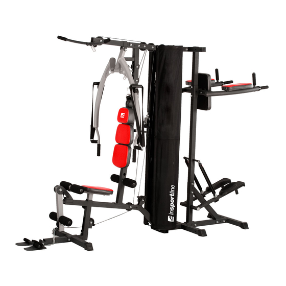
- Page 1 User manual-EN IN 333 Home Gym inSPORTline Phanton...
-
Page 2: Table Of Contents
Part list: Part No. Description Q’ty Part No. Description Q’ty Main frame Bushing D29*D21.5*D10.2 Middle floor frame Fixing plate 50*120*3T Front vertical support Computer BC-80258 Top frame Upper computer cable 720L Front floor frame Middle computer cable 550L Seat support Lower computer cable 400L Left butterfly arm Sensor cable 110L... - Page 3 Buffer 35*35*25 Bolt M10*1.5*75L Square buffer 42*42*5T Flat washer D20*D11*2T Round buffer D60*D26*26T Nylon nut M10*1.5*10T Allen spanner Bolt M10*1.5*65L Pulley guidance Bolt M10*1.5*70L Plastic ring of pulley Screw M8*25L Bushing D38*D35.2*32 Flat washer D24*D13.5*2.5T Foam D23*D80*175L Nylon nut M12*1.75*12T Foam D23*D35*127L Bolt M10*1.5*55L Upper weight plate...
- Page 4 Exploded drawing...
- Page 5 Checking list...
- Page 6 M6*1*40L M10*25 D15*D5.2*1.0T M6*1*35L M10*40 D14*D6.5*0.8T M10*20 M10*55 D15.4*D8.2*2T M8*25 M10*60 D19*D8.5*1.6T M8*20L M8*65 M5*0.8*20L D20*D11*2T M10*65 M6*1*20L M10*70 M8*15L D24*D13.5*2.5T M10*75 M6*1*6T D28*D8.5*3T M12*85 M10*10T M10*95 D18*14.5T M12*12T D10.5*56.5 D47.5xD13 D56xD27...
-
Page 7: Main Frame (
Assembly drawing Step 1 M10*1.5*10T D20*D11*2T M10*1.5*20L M10*1.5*25L FIG1 M10*1.5*70L 1) Assemble the main frame (1) to the middle floor frame (2) by the flat washer (101), the nylon nut (102) and the bolt (104). 2) Assemble the lower weight protector (27) and the chrome guidance (16) to the middle floor frame (2) by the flat washer (101), the bolt (110) and the bolt (114) shown as fig. -
Page 8: Front Floor Frame 1
Step 2 M10*1.5*10T D20*D11*2T M10*1.5*65L FIG2 M10*1.5*75L 1) Assemble the lower weight plate (47), the mid weight plate (97) and the upper weight plate (46) to the chrome guidance (16) shown as fig. A. Put the flat washer (54) on the hole of the upper weight plate (46). 2) Assemble the upper weight selector socket (55) to the weight selector tube (18) and fix the socket by the upper weight selector pin (53). - Page 9 Step 3 M10*1.5*10T D20*D11*2T D19*D8.5*1.6T M8*15L FIG3 M10*1.5*40L M10*1.5*65L M10*1.5*70L M10*1.5*75L 1) Assemble the front vertical support (3) to the main frame (1) by the fixing plate (65), the flat washer (101), the bolt (104) and the nylon nut (102). 2) Assemble the seat (49) to the seat support (6) by the flat washer (101) and the bolt (109) shown as fig.
- Page 10 Step 4 M10*1.5*10T D20*D11*2T M12*1.75*12T D24*D13.5*2.5T M10*1.5*25L M10*1.5*75L M12*1.75*85L FIG4 1) Assemble the top frame (4) to the chrome guidance (16) and the front vertical support (3). Assemble the square cap (35) to the top frame (4). 2) Assemble the upper weight protector support (28) to the top frame. 3) Fix the upper weight protector support (28), the top frame (4) and the chrome guidance (16) by the flat washer (101) and the bolt (114).
-
Page 11: Butterfly Arm Support 1
Step 5 M10*1.5*10T D20*D11*2T M8*1.25*25L FIG5 M10*1.5*95L 1) Assemble the butterfly arm support (9) to the top frame (4) by the flat washer (101), the nylon nut (102) and the bolt (113). 2) Assemble the left butterfly arm (7) and the right butterfly arm (8) to the butterfly arm support (9) by the screw (105). 3) Attach the square buffer (38) on the butterfly arm support (9) shown as fig A. -
Page 12: Leg Extension Tube 1
Step 6 D12*D10*7T D20*D11*2T FIG6 M10*1.5*25L 1) Assemble the belt (fabric) (15) to the left butterfly arm (7) and the right butterfly arm (8) by the bushing (31), the flat washer (101) and the bolt (114). 2) Assemble the foam roller axle (14) to the front vertical support (3), the seat support (6) and the leg extension tube (11). - Page 13 Step 7 M10*1.5*10T D20*D11*2T M10*1.5*25L M10*1.5*60L FIG7 M10*1.5*65L D18*D10*14.5T 1) Assemble the flat pulley (57) to the top frame (4) by the bushing (60), the bolt (103) and the nylon nut (102) shown as fig. A. 2) Assemble the raised pulley (56) to the butterfly arm support (9) by the flat washer (101) and the nylon nut (102) shown as fig.
- Page 14 Step 8 M10*1.5*10T D20*D11*2T M10*1.5*25L M10*1.5*55L M10*1.5*60L M10*1.5*65L FIG8 D18*D10*14.5T 1) Assemble the flat pulley (57) to the front vertical support (3) by the bushing (60), the bolt (103) and the nylon nut (102) shown as fig. A. 2) Assemble the raised pulley (56) to the single pulley bracket (20) by the pulley guidance (41), the plastic ring of pulley (42), the flat washer (101), the bolt (112) and the nylon nut (102) shown as fig.
-
Page 15: Lower Weight Protector 2
Step 9 M5*0.8*20L D15*D5.2*1.0T FIG9 M6*1*20L D14*D6.5*0.8T M6*1*6T 1) Assemble the curved plate (94) to the weight protector (17) by the bolt (117), the flat washer (118) and the nylon nut (119). 2) Assemble the weight protector (17) to the lower weight protector support (27) and the upper weight protector support (28) by the bolt (115) and the flat washer (116). -
Page 16: Nip For Computer Cable
Step 10 FIG10 1) Assemble the computer (66) to the front vertical support (3). 2) Connect the cable that is pre-assembled to the computer (66) with the middle computer cable (68) shown as fig. A. 3) Fix the middle computer cable (68) by the nip for computer cable (72) shown as fig. B. 4) Connect the upper computer cable (67) with the middle computer cable (68) shown as fig. -
Page 17: Rear Vertical Support
Step 11 M10*1.5*10T D20*D11*2T M10*1.5*65L M10*1.5*75L FIG11 1) Assemble the rear vertical support (74) to the top frame (4) by the flat washer (101), the nylon nut (102) and the bolt (103). 2) Assemble the rear floor frame (75) to the middle floor frame (2) and the rear vertical support (74) by the flat washer (101), the bolt (100) and the nylon nut (102). -
Page 18: Arm Pad Support
Step 12 M10*1.5*10T D20*D11*2T D19*D8.5*1.6T M8*20L M8*1.25*65L M10*1.5*65L M10*1.5*75L FIG12 1) Assemble the arm pad support (77) to the rear vertical support (74) by the bolt (100), the flat washer (101) and the nylon nut (102). 2) Assemble the backrest (80) to the arm pad support (77) by the flat washer (101) and the bolt (103). 3) Assemble the left arm pad (79L) and the right arm pad (79R) to the arm pad support (77) by the flat washer (123) and the bolt (128). -
Page 19: Right Pedal Support
Step 13 D28*D8.5*3T D15.4*D8.2*2T D14*D6.5*0.8T M8*20L M6*1*35L M6*1*40L FIG13 1) Assemble the left pedal support (81L) and the right pedal support (81R) to the rear vertical support (74) by the flat washer (121), the bolt (125) and the spring washer (126). 2) Assemble the Hydraulic cylinder (83) to the rear vertical support (74) by the flat washer (121), the bolt (125) and the spring washer (126). - Page 20 Step 14 FIG14 Assemble the screw cap (61&62&90&91) to the screws.
-
Page 21: Seat
Notes 1) Users could pull the butterfly arm forward and backward according to different target for exercise shown as fig. 1-1 and fig 1-2. 2) The plate for foot could be adjusted vertically shown as fig. 2. 3) The height of the seat could be adjusted by turning the knob shown as fig. B. 4) Users could select the quantity of the weight plates by the ball pin. - Page 22 The VKR+STEPPER could be adjusted in different positions shown as fig. 5-1/2/3. 1. Back part of the item; 2. Left part of the item; 3. Right part of the item.
- Page 23 Computer instruction (BC-80258) BATTERY ASSEMBLY 1. Take the computer that has been supplied out of the packaging and insert the battery <1.5V cell>according to the illustration on the back of the computer 2. Connect the computer and the unit with the cable as shown in the following drawing and then push the computer into the locator on the covering cap.
- Page 24 OPERATION 1.(Windows=1) When battery is installed, LCD will display all graphics for 1 second, and following with 1 second BEEP. Console will go into FUNCTION TEST mode, by displaying wheel size (for 1 second), then display Cal value (for 1 second), then return to TIME FUNCTION.
Need help?
Do you have a question about the 333 and is the answer not in the manual?
Questions and answers