Table of Contents
Advertisement
Quick Links
Advertisement
Table of Contents

Related Manuals for Insportline Phanton


Summary of Contents for Insportline Phanton
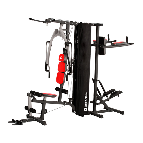
- Page 1 USER MANUAL – EN IN 18397 Multi-Gym inSPORTline Phanton...
-
Page 2: Table Of Contents
EXPLODED DRAWING ........................... 7 ASSEMBLY ............................10 L SHAPE ASSEMBLY ........................... 26 COMPUTER INSTRUCTION (ST3155) ....................29 EXERCISES AVAILABLE ON MULTI-GYM INSPORTLINE PHANTON ..........30 EXERCISE ............................. 30 ENVIRONMENT PROTECTION ......................31 TERMS AND CONDITIONS OF WARRANTY, WARRANTY CLAIMS ..........31... -
Page 3: Safety Instructions
SAFETY INSTRUCTIONS INTRODUCTION Thank you for purchasing this device. Check that all parts are complete and faultless. If any part is missing, contact the service. Also, contact the servicer in case of repair or damage. This device is intended only for home use. Another than intended use can void the warranty. Don’t use it for commercial purposes. - Page 4 Safety precautions: Follow these instructions to use it safely: 1) The max. load is: 150 kg. 2) Certified as per EN957 in class HC. For home use only. 3) Don’t use it in places with lack of air. 4) Protect from extreme temperatures, water and humidity. 5) Read the manual carefully before starting any workout.
-
Page 5: Parts List
PARTS LIST Part Part Q’ty Q’ty Description Description Main frame Bushing D29*D21.5*D10.2 Middle floor frame Fixing plate 50*120*3T Front vertical support Computer BC-80258 Top frame Upper computer cable 720L Front floor frame Middle computer cable 550L Seat support Lower computer cable 400L Left butterfly arm Sensor cable 110L Right butterfly arm... - Page 6 Round cap D1’’*17.5 Fixing bracket Hydraulic cylinder Spanner Curved plate Square cap 50*50*18.5 Fixing tube Square cap 50*50*20L Hollow cap D50.8*D26*D20L Square cap 20*50*14 Mid weight plate Buffer 35*35*25 Bolt M10*1.5*75L Square buffer 42*42*5T Flat washer D20*D11*2T Round buffer D60*D26*26T Nylon nut M10*1.5*10T Allen spanner Bolt M10*1.5*65L...
-
Page 7: Exploded Drawing
EXPLODED DRAWING... - Page 8 Checking list...
- Page 9 M6*1*40L M10*25 D15*D5.2*1.0T M6*1*35L M10*40 D14*D6.5*0.8T M10*20 M10*55 D15.4*D8.2*2T M8*25 M10*60 D19*D8.5*1.6T M8*20L M8*65 M5*0.8*20L D20*D11*2T M10*65 M6*1*20L M10*70 M8*15L D24*D13.5*2.5T M10*75 M6*1*6T D28*D8.5*3T M12*85 M10*10T M10*95 D18*14.5T M12*12T D10.5*56.5 D47.5xD13 D56xD27...
-
Page 10: Assembly
ASSEMBLY Step 1 M10*1.5*10T D20*D11*2T M10*1.5*20L M10*1.5*25L FIG1 M10*1.5*70L 1) Assemble the main frame (1) to the middle floor frame (2) by the flat washer (101), the nylon nut (102) and the bolt (104). 2) Assemble the lower weight protector (27) and the chrome guidance (16) to the middle floor frame (2) by the flat washer (101), the bolt (110) and the bolt (114) shown as fig. - Page 11 Step 2 M10*1.5*10T D20*D11*2T M10*1.5*65L FIG2 M10*1.5*75L 1) Assemble the lower weight plate (47), the mid weight plate (97) and the upper weight plate (46) to the chrome guidance (16) shown as fig. A. Put the flat washer (54) on the hole of the upper weight plate (46).
- Page 12 Step 3 M10*1.5*10T D20*D11*2T D19*D8.5*1.6T M8*15L FIG3 M10*1.5*40L M10*1.5*65L M10*1.5*70L M10*1.5*75L 1) Assemble the front vertical support (3) to the main frame (1) by the fixing plate (65), the flat washer (101), the bolt (104) and the nylon nut (102). 2) Assemble the seat (49) to the seat support (6) by the flat washer (101) and the bolt (109) shown as fig.
- Page 13 Step 4 M10*1.5*10T D20*D11*2T M12*1.75*12T D24*D13.5*2.5T M10*1.5*25L M10*1.5*75L M12*1.75*85L FIG4 1) Assemble the top frame (4) to the chrome guidance (16) and the front vertical support (3). Assemble the square cap (35) to the top frame (4). 2) Assemble the upper weight protector support (28) to the top frame. 3) Fix the upper weight protector support (28), the top frame (4) and the chrome guidance (16) by the flat washer (101) and the bolt (114).
- Page 14 M10*1.5*10T D20*D11*2T M8*1.25*25L FIG5 M10*1.5*95L 1) Assemble the butterfly arm support (9) to the top frame (4) by the flat washer (101), the nylon nut (102) and the bolt (113). 2) Assemble the left butterfly arm (7) and the right butterfly arm (8) to the butterfly arm support (9) by the screw (105).
- Page 15 Step 6 D12*D10*7T D20*D11*2T FIG6 M10*1.5*25L 1) Assemble the belt (fabric) (15) to the left butterfly arm (7) and the right butterfly arm (8) by the bushing (31), the flat washer (101) and the bolt (114). 2) Assemble the foam roller axle (14) to the front vertical support (3), the seat support (6) and the leg extension tube (11).
- Page 16 Step 7 M10*1.5*10T D20*D11*2T M10*1.5*25L M10*1.5*60L FIG7 M10*1.5*65L D18*D10*14.5T Assemble the flat pulley (57) to the top frame (4) by the bushing (60), the bolt (103) and the nylon nut (102) shown as fig. A. Assemble the raised pulley (56) to the butterfly arm support (9) by the flat washer (101) and the nylon nut (102) shown as fig.
- Page 17 M10*1.5*10T D20*D11*2T M10*1.5*25L M10*1.5*55L M10*1.5*60L M10*1.5*65L FIG8 D18*D10*14.5T 1) Assemble the flat pulley (57) to the front vertical support (3) by the bushing (60), the bolt (103) and the nylon nut (102) shown as fig. A. 2) Assemble the raised pulley (56) to the single pulley bracket (20) by the pulley guidance (41), the plastic ring of pulley (42), the flat washer (101), the bolt (112) and the nylon nut (102) shown as fig.
- Page 18 M5*0.8*20L D15*D5.2*1.0T FIG9 M6*1*20L D14*D6.5*0.8T M6*1*6T 1) Assemble the curved plate (94) to the weight protector (17) by the bolt (117), the flat washer (118) and the nylon nut (119). 2) Assemble the weight protector (17) to the lower weight protector support (27) and the upper weight protector support (28) by the bolt (115) and the flat washer (116).
- Page 19 FIG10 1) Assemble the computer (66) to the front vertical support (3). 2) Connect the cable that is pre-assembled to the computer (66) with the middle computer cable (68) shown as fig. A. 3) Fix the middle computer cable (68) by the nip for computer cable (72) shown as fig. B. 4) Connect the upper computer cable (67) with the middle computer cable (68) shown as fig.
- Page 20 M10*1.5*10T D20*D11*2T M10*1.5*65L M10*1.5*75L FIG11 1) Assemble the rear vertical support (74) to the top frame (4) by the flat washer (101), the nylon nut (102) and the bolt (103). 2) Assemble the rear floor frame (75) to the middle floor frame (2) and the rear vertical support (74) by the flat washer (101), the bolt (100) and the nylon nut (102).
- Page 21 Step 12 M10*1.5*10T D20*D11*2T D19*D8.5*1.6T M8*20L M8*1.25*65L M10*1.5*65L M10*1.5*75L FIG12 1) Assemble the arm pad support (77) to the rear vertical support (74) by the bolt (100), the flat washer (101) and the nylon nut (102). 2) Assemble the backrest (80) to the arm pad support (77) by the flat washer (101) and the bolt (103).
- Page 22 Step 13 D28*D8.5*3T D15.4*D8.2*2T D14*D6.5*0.8T M8*20L M6*1*35L M6*1*40L FIG13 1) Assemble the left pedal support (81L) and the right pedal support (81R) to the rear vertical support (74) by the flat washer (121), the bolt (125) and the spring washer (126). 2) Assemble the Hydraulic cylinder (83) to the rear vertical support (74) by the flat washer (121), the bolt (125) and the spring washer (126).
- Page 23 Step 14 FIG14 Assemble the screw cap (61&62&90&91) to the screws.
- Page 24 Notes 1) Users could pull the butterfly arm forward and backward according to different target for exercise shown as fig. 1-1 and fig 1-2. 2) The plate for foot could be adjusted vertically shown as fig. 2. 3) The height of the seat could be adjusted by turning the knob shown as fig. B. 4) Users could select the quantity of the weight plates by the ball pin.
- Page 25 The VKR+STEPPER could be adjusted in different positions shown as fig. 5-1/2/3. 1. Back part of the item; 2. Left part of the item; 3. Right part of the item.
-
Page 26: L Shape Assembly
L SHAPE ASSEMBLY Follow steps 1 through 10 above to assemble the L-shaped tower. The L-shape assembly steps are described in steps 11-14 below. STEP 11 On the top, attach the rear frame (74) to the upper frame (4) using 4x washers (101), 2x nuts (102) and 2x screws (103). - Page 27 STEP 12 Attach the armrest support (77) to the rear vertical frame (74) with 2x screws (100), 4x washers (101) and 2x nuts (102) Attach the backrest (80) to the armrest support (77) with 2x screws (103) and 2x washers (101). Attach the left and right arm supports (79 L / R) to the arm supports (77) using 4x screws (128) and 4x washers (123).
- Page 28 STEP 13 Attach the left and right pedal supports (81 L / R) to rear vertical frame (74) with 2x screws (125), 2x spring washers (126) and 2x flat washers (125). Attach the hydraulic cylinder (83) to the rear vertical frame (74) with 2x screws (125), 2x spring washers (126) and 2x flat washers (121).
-
Page 29: Computer Instruction (St3155)
STEP 14 Attach the caps (61, 62, 90, 91) to the screws. COMPUTER INSTRUCTION (ST3155) Button function: MODE/RESET – press to select pre-set functions or hold for total reset of all functional values Functions: STOP – when you stop pedalling, STOP will be displayed on the screen STRIDES/MIN –... -
Page 30: Exercises Available On Multi-Gym Insportline Phanton
EXERCISES AVAILABLE ON MULTI-GYM INSPORTLINE PHANTON • Biomechanical linear movement provided by the patented design with a wide range of adjustment options • Stair stepper with adjustable resistance • Parallel bars for dips and intense ab exercises • Butterfly station for chest muscle exercises (as well as rhomboid muscle exercises) •... -
Page 31: Environment Protection
Recommended maintenance: Maintain it regularly according to its workload, but at least every 20 hours of working. Maintenance includes: • Check all moving parts (shafts, joints etc.). Check proper lubrication. Add oil, if necessary. Use: bike oil, oil for sewing machines, silicone oil. •... - Page 32 “The Buyer who is not the End Customer” is a Businessman that buys Goods or uses services for the purpose of using the Goods or services for his own business activities. The Buyer conforms to the General Purchase Agreement and business conditions. These Conditions of Warranty and Warranty Claims are an integral part of every Purchase Agreement made between the Seller and the Buyer.
- Page 33 26847264 VAT ID: CZ26847264 Phone: +420 556 300 970 E-mail: eshop@insportline.cz reklamace@insportline.cz servis@insportline.cz Web: www.inSPORTline.cz inSPORTline s.r.o. Headquaters, warranty & service center: Električná 6471, Trenčín 911 01, SK CRN: 36311723 VAT ID: SK2020177082 Phone: +421(0)326 526 701 E-mail: objednavky@insportline.sk reklamacie@insportline.sk servis@insportline.sk...
Need help?
Do you have a question about the Phanton and is the answer not in the manual?
Questions and answers