Table of Contents
Advertisement
Advertisement
Table of Contents

Related Manuals for Sirona CEREC Radio Device


Summary of Contents for Sirona CEREC Radio Device
- Page 1 CEREC Radio Device Operating Manual This document contains a functional and operational manual for the CEREC Radio Device which implements a wireless network to be used for the communication between acquisition units and milling units in the CEREC system. 1/33...
-
Page 2: Table Of Contents
3. Specification 4. System description CEREC system System components Main function Network unit 5. Networking CEREC Radio Device network overview Creating a network 5.2.1 Creation 5.2.2 Isolated network unit 5.2.3 Persistent network 5.2.4 Installation 5.2.5 Maximum size Network creation failures 5.3.1 Isolated network unit... - Page 3 6.2.3 Multiple streams Transmit data using LAN 6.3.1 LAN routing 6.3.2 Handover 6.3.3 Simultaneous access Interrupted transmission 3/33...
-
Page 4: Introduction
CEREC Radio Device (part no. 6543891 D3492) is a powerful 100 Base-T Ethernet wireless transmission system that allows peripheral devices to build up a wireless network or to access a wired network. The CEREC Radio Device operates in the 2.4 GHz ISM band and complies with FCC, IC and EC regulations. -
Page 5: Fcc And Ic Declarations
Do not open the CEREC Radio Device. The CEREC Radio Device does not contain parts which could be maintained, exchanged or repaired by the customer or non-authorized maintenance personnel. Opening the device can damage the electric components. A correctly functioning device is no longer guaranteed! 1.2 FCC and IC Declarations... -
Page 6: Product Description
Product Description 2.1 Operational Elements Ethernet Micro B USB Ethernet RJ45 connector for Ethernet 100 Base-T with red and green LED DC Input Micro B USB connector for 5V DC power supply Reset Reset Opening to press reset button. Use small object to press. LED Indications 6/33... - Page 7 Two LEDs are used to indicate the device’s state. Each LED can have the following states: 1. Off 2. Slow blinking 3. Fast blinking 4. On The following table shows potential states for the device: State Orange Green Comment Booting Both LEDs are not yet functional.
-
Page 8: Specification
Specifications Dimensions: Approx. 104 x 75 x 24 mm³ Weight: Approx. 100 g Operating Temperature: 0...40 °C Storage Temperature: -25..80 °C Power Supply: 5.0 V DC (1.4 W max.) Data Interface: 100 Base-T Ethernet Radio Band: 2402 .. 2480 MHz Transmit Power: Max. -
Page 9: System Description
System Description This chapter describes the context of the CEREC Radio Device by describing the main function and identifying the system components. 4.1 CEREC System Mobile acquisition unit and a stationary milling unit. The acquisition unit generates the restoration data which is to be transmitted to the milling unit. -
Page 10: Main Function
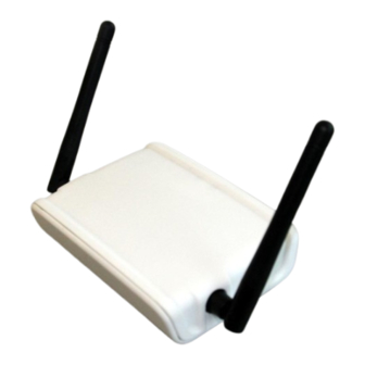
4.3 Main Function The objective of the CEREC Radio Device is to obtain a reliable wireless data connection between a stationary milling unit and a mobile acquisition unit. The wireless network that is created can then be used to transmit time constraint data. - Page 11 As illustrated, the network unit has four connectors: ● Antenna The network unit has two antennas that are screwed on during production. Do not remove these antennas or use different antennas. ● Micro B USB For power the network unit has a standard micro B USB connector. A standard supplied 5V power adapter can be plugged into this connection.
-
Page 12: Networking
Networking This section describes the networking functionality of the CEREC Radio Device. The following lists the chapters: ● CEREC Radio Device network overview ● Creating a network ● Network creation failures ● Extending the network ● Increasing network coverage ●... -
Page 13: Cerec Radio Device Network Overview
5.1 CEREC Radio Device Network Overview The network units in the CEREC Radio Device network create a so called peer-to-peer mesh network. This means that there is not a master or slave as with Bluetooth or a central controlling access point as with Wi-Fi. -
Page 14: Creating A Network
5.2 Creating a Network Network units that come out of the box have never been part of a network. To allow for several networks of different owners to operate side-by-side or in the same area, new network units must first create a network. This is described in the following section. 5.2.1 Creation To create a new network with a number of new network units the following steps must be completed:... -
Page 15: Network Creation Failures
5.3 Network Creation Failures The following chapter describes potential issues which could arise when creating a new network and offers solutions for each scenario. 5.3.1 Isolated Network Unit When a single network unit is powered-up too late it may not be part of the network. This can be identified if the LED does not turn green. -
Page 16: Extending The Network
5.4 Extending the Network Additional new network units can be added to an existing network. This section explains how this is done. 5.4.1 Add New Network Unit New network units can be added to an existing network. However, to prevent any network unit from becoming part of the network, the user must complete four simple but specific steps: 1. -
Page 17: Increasing Network Coverage
LAN cables. Simply placing an extra network unit in between two network units that are out-of-range does not work since this would mean relaying data from wireless to wireless. This is not implemented in the CEREC Radio Device because this would quickly lead to unsatisfactory performance in most cases. -
Page 18: Connecting To Ethernet Infrastructure
5.5.2 Connecting to Ethernet Infrastructure The network units can also be connected to an existing LAN infrastructure. In this way, the flexibility of increasing the coverage is very straightforward. 5.6 Reset to Factory Defaults A network unit that was previously part of a network can be removed from this network. This is completed by holding the reset button for five seconds. -
Page 19: Network Unit States
5.7 Network Unit The proper behavior of a network unit can be identified by its state. This chapter describes the states that can be identified for a network unit. To provide feedback on the proper operation of the network unit to the user, these states are also mapped onto LED indications. - Page 20 The transitions are described in the following table: State Transition Description Initial Power-up Boot program starts-up after reboot or power on. Booting Ready The firmware is started. Read network No network The network unit was not previously part of a network. A info network setup timer of 1 minute...
-
Page 21: Led Indications
5.7.3 LED Indications 1. Two LEDs are used to indicate the device’s state. Each LED can have the following states: Off 2. Slow blinking 3. Fast blinking 4. On The following table shows potential states for the device: State Orange Green Comment Booting... -
Page 22: Radio Characteristics
5.8.1 Frequency Spectrum The CEREC Radio Device network units each receive a 2 MHz channel assigned in the 2.4 GHz band. The Wi-Fi channels in this band are illustrated in the figure below. 5.8.2 Channel Control Each network unit uses a specific channel on which it can receive data. -
Page 23: Use Cases
6.Use Cases To further explain the functionality as implemented in the CEREC Radio Device, this section describes the scenarios of some use cases in more detail. The following use cases are described: ● Moving around ● Transmit data wirelessly ●... -
Page 24: Moving Around
6.1 Moving Around One of the obvious benefits of having a wireless network is that the acquisition units can be moved to different locations. When moved the acquisition unit can be moved in and outof the range of other network units. This chapter describes some typical scenarios. 6.1.1 Moving Within Network While being moved, the mobile network unit always stays within one or more network units. -
Page 25: Temporarily Disconnected
6.1.2 Temporarily Disconnected While being moved, the mobile network unit temporarily moves outside the network clusters and has no more connection. Preconditions: ● The mobile network unit is in range of stationary network unit A. ● The mobile network unit is out ofthe range of stationary network unit B. Sequence: 1. -
Page 26: Disconnected
6.1.3 Disconnected While being moved, the mobile network unit moves outside the clusters and loses the connection to the network. Preconditions: ● The mobile network unit is in range of the stationary network unit. Sequence: 1. The mobile network unit is pushed away from the stationary network unit. 2. -
Page 27: Transmit Data Wirelessly
6.2 Transmit Data Wirelessly This chapter describes the scenarios of the use cases in which the system does not use LAN infrastructure to communicate, but only the peer-to-peer mesh network. 6.2.1 Stationary Data Transmission The mobile network unit stays connected to the same stationary network unit while transferring the data. -
Page 28: Network Routing
6.2.2 Network Routing The mobile network unit has a connection to several stationary network units that each are connected to a milling unit. Therefore the mobile network unit has to determine which stationary network unit to use. Preconditions: ● The acquisition unit is in range of two stationary network units A and B. ●... -
Page 29: Multiple Streams
6.2.3 Multiple Streams The mobile network unit has a connection to several stationary network units that each are connected to a milling unit. The acquisition unit is transmitting data to all milling units. Preconditions: ● The acquisition unit is in range of two stationary network units A and B. ●... -
Page 30: Transmit Data Using Lan
6.3 Transmit Data Using LAN As described in “Increasing network coverage”, data can also be transmitted by using LAN as a means of increasing the coverage of the network. The main scenarios associated with this functionality are described in this chapter. 6.3.1 LAN Routing In the example below the mobile network unit has a connection with two stationary network units which are connected to the same the LAN infrastructure as the milling... -
Page 31: Handover
6.3.2 Handover The mobile network unit moves out of the range of the stationary network unit that it uses for data transmission to the milling unit and consequently loses the connection. When it is in range of another stationary unit, the mobile network unit will switch to that one. -
Page 32: Simultaneous Access
6.3.3 Simultaneous Access Several acquisition units are transmitting their data via the same stationary network unit. For acquisition unit B the effective data rate is lower than compared to the situation if the stationary network unit was not shared. 32/33... -
Page 33: Interrupted Transmission
6.4 Interrupted Transmission The acquisition unit is pushed out of the range of the stationary network unit and no alternative path to the milling unit is available. Sequence: 1. The acquisition unit is pushed out of the range of the stationary network unit. 2.
Need help?
Do you have a question about the CEREC Radio Device and is the answer not in the manual?
Questions and answers