Table of Contents
Advertisement
Quick Links
Download this manual
See also:
Operating Manual
Advertisement
Table of Contents

Related Manuals for Sirona Cerec

Summary of Contents for Sirona Cerec
- Page 1 MRKOMNR kÉï=~ë=çÑW== `bob`=o~Çáç=aÉîáÅÉ léÉê~íáåÖ=fåëíêìÅíáçåë båÖäáëÜ båÖäáëÜ Operating Instructions...
-
Page 2: Table Of Contents
LED displays ..................Technical data ......................System description ....................CEREC system ..................... System components..................Main function....................Network unit ....................Networking ....................... CEREC Radio Device network overview ............Creating a network ..................6.2.1 Creation.................... 6.2.2 Isolated network unit ................ 6.2.3 Permanent network ................ - Page 3 Sirona Dental Systems GmbH Table of contents Operating Instructions CEREC Radio Device 6.4.2 Reducing the network..............Resetting to factory defaults................. Network unit states..................6.6.1 State definitions................6.6.2 Transitions between states.............. Radio characteristics ..................6.7.1 Frequency spectrum................ 6.7.2 Channel control ................
-
Page 4: General Data
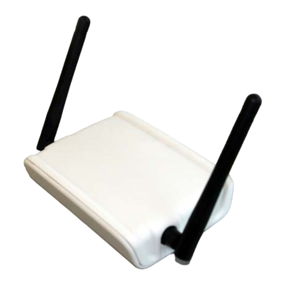
Thank you for purchasing your CEREC Radio Device from Sirona. General description This CEREC Radio Device allows you to set up a wireless network for communication between acquisition units and milling units. The CEREC Radio Device (REF 65 43 891 D3492) is a powerful, wireless... -
Page 5: General Information About This Operating Manual
Online portal for technical documents We have set up an online portal for the Technical Documents at http:// www.sirona.com/manuals. From here, you can download these Operating Instructions along with other documents. Please complete the online form if you would like a hard copy of a particular document. We will then be happy to send you a printed copy free of charge. -
Page 6: Formats And Symbols Used
1 General data Sirona Dental Systems GmbH 1.4 Structure of the document Operating Instructions CEREC Radio Device 1.4.2 Formats and symbols used The formats and symbols used in this document have the following meaning: Prerequisite Prompts you to do something. 1. First action step 2. -
Page 7: Safety Instructions
Do not insert any objects in the openings of the unit, unless this is explicitly instructed in this document. This could damage the unit. Do not open the CEREC Radio Device! It does not contain any parts that could be serviced, replaced, or repaired by customers or by any unauthorized maintenance personnel. -
Page 8: Fcc And Ic Declarations
2 Safety instructions Sirona Dental Systems GmbH 2.2 FCC and IC declarations Operating Instructions CEREC Radio Device FCC and IC declarations Compliance statement Fragment nicht übersetzen This device complies with part 15 of the FCC Rules and to Industry Canada’s license-exempt RSSs. -
Page 9: Ec Declaration Of Conformity
Sirona Dental Systems GmbH 2 Safety instructions Operating Instructions CEREC Radio Device 2.3 EC Declaration of Conformity EC Declaration of Conformity 65 45 177 D3492 D3492.201.09.01.02 05.2015... -
Page 10: Product Description
3 Product description Sirona Dental Systems GmbH 3.1 Main components of the product Operating Instructions CEREC Radio Device Product description Main components of the product 3.1.1 Controls Ethernet RJ45 port for Ethernet 100 Base-T with red and green LED DC input Micro-B USB connector for 5 VDC power... -
Page 11: Led Displays
Sirona Dental Systems GmbH 3 Product description Operating Instructions CEREC Radio Device 3.1 Main components of the product 3.1.2 LED displays Two LEDs indicate the condition of the unit. Each LED may have the following states: ● Off ● Slowly flashing ● Quickly flashing ●... -
Page 12: Technical Data
4 Technical data Sirona Dental Systems GmbH Operating Instructions CEREC Radio Device Technical data Dimensions: Approx. 104 x 75 x 24 mm Weight: Approx. 100 g Operating temperature: 0 to 40°C Storage temperature: -25 to 80°C Power supply: 5 VDC (max. 1.4 W) -
Page 13: System Description
This section explains the context of the CEREC Radio Device by describing the main function and identifying the system components. CEREC system The CEREC system consists of a mobile acquisition unit and a stationary milling unit. The acquisition unit generates the restoration data which is transmitted to the milling unit. -
Page 14: System Components
5 System description Sirona Dental Systems GmbH 5.2 System components Operating Instructions CEREC Radio Device System components The identifiable components and their role in the CEREC system are presented below: Component Description Role Symbol Acquisition unit The PC platform used for recording Data source. -
Page 15: Main Function
5.3 Main function Main function The objective of the CEREC Radio Device is to obtain a reliable, wireless data connection between a stationary milling unit and a mobile acquisition unit. The wireless network that is created can then be used to transmit time-dependent data. -
Page 16: Network Unit
Operating Instructions CEREC Radio Device Network unit The CEREC Radio Device enables the setting up of a range of wireless network units that together create a wireless network. The number of network units in one network is limited to three. These network units... - Page 17 However, any standard USB 3.0 connection can be used to power the network unit. The network unit integrated in the CEREC mobile acquisition unit is powered through this port. ● RJ-45 The network unit has an RJ45 interface to which the standard network cable (CAT5) can be connected.
-
Page 18: Networking
● Radio characteristics CEREC Radio Device network overview The network units in the CEREC Radio Device network create a so-called peer-to-peer mesh network. This means that there is not a master or slave as with Bluetooth, nor a central controlling access point for the control as with WLANs. -
Page 19: Creation
Sirona Dental Systems GmbH 6 Networking Operating Instructions CEREC Radio Device 6.3 Network creation failures 6.2.1 Creation To create a new network with a number of new network units the following steps must be completed: 1. Bring all network units together in one room. -
Page 20: Multiple Networks Created
6 Networking Sirona Dental Systems GmbH 6.4 Extending the network Operating Instructions CEREC Radio Device 6.3.2 Multiple networks created When more than one network unit is powered-up too late, these network units could form their own network. Initially this will not be clear because all network units will indicate that connections to other network units have been established with a green LED (see “LED displays [ →... -
Page 21: Reducing The Network
Sirona Dental Systems GmbH 6 Networking Operating Instructions CEREC Radio Device 6.4 Extending the network 6.4.2 Reducing the network In some cases it may be necessary to remove one or more network units from an existing network. Sequence: 1. One network unit is switched-off. -
Page 22: Resetting To Factory Defaults
6 Networking Sirona Dental Systems GmbH 6.5 Resetting to factory defaults Operating Instructions CEREC Radio Device Resetting to factory defaults A network unit that was previously part of a network can be removed from this network. ➢ This is completed by holding the reset button for five seconds. -
Page 23: Transitions Between States
Sirona Dental Systems GmbH 6 Networking Operating Instructions CEREC Radio Device 6.6 Network unit states 6.6.2 Transitions between states The transitions between these states are given in the following figure: These transitions are described in the table below: State Next state Description... -
Page 24: Radio Characteristics
6.7.1 Frequency spectrum The CEREC Radio Device network units each receive a 2 MHz channel, assigned to them in the 2.4 GHz band. The WLAN channels in this band are illustrated in the figure below. -
Page 25: Data Transmission
7 Data transmission Operating Instructions CEREC Radio Device 7.1 Stationary data transmission Data transmission To further explain the functionality of the CEREC Radio Device, this section describes how data is transmitted in various cases: ● Stationary data transmission ● Network routing ● Multiple streams ●... -
Page 26: Network Routing
7 Data transmission Sirona Dental Systems GmbH 7.2 Network routing Operating Instructions CEREC Radio Device Network routing The mobile network unit has connections to several stationary network units that each are connected to a milling unit. Therefore the mobile network unit has to determine which stationary network unit to use. -
Page 27: Multiple Streams
Sirona Dental Systems GmbH 7 Data transmission Operating Instructions CEREC Radio Device 7.3 Multiple streams Multiple streams The mobile network unit has connections to several stationary network units that each are connected to a milling unit. The acquisition unit sends data to all milling units. -
Page 28: Simultaneous Access
7 Data transmission Sirona Dental Systems GmbH 7.4 Simultaneous access Operating Instructions CEREC Radio Device Simultaneous access Several acquisition units are transmitting their data via the same stationary network unit. For the acquisition units the effective data rate is lower than compared to a situation where the stationary network unit was not used together with other acquisition units. -
Page 29: Interrupted Transmission
Sirona Dental Systems GmbH 7 Data transmission Operating Instructions CEREC Radio Device 7.5 Interrupted transmission Interrupted transmission The acquisition unit is removed from the range of the stationary network unit and no alternative connection to the milling unit is available. Sequence: The acquisition unit is removed from the range of the stationary network unit. -
Page 30: Increasing The Range
7 Data transmission Sirona Dental Systems GmbH 7.6 Increasing the range Operating Instructions CEREC Radio Device Increasing the range If the distance between the acquisition unit and the stationary network unit of the milling unit is too long to establish a direct connection, there is the possibility to extend the range by using two additional network units which have to be paired as a separate network. -
Page 31: Disposal
Sirona Dental Systems GmbH 8 Disposal Operating Instructions CEREC Radio Device Disposal Your product is marked with the adjacent symbol. Within the European Environmentally sound disposal Economic Area, this product is subject to Directive 2002/96/EC as well as the corresponding national laws. This directive requires environmentally sound recycling / disposal of the product. - Page 32 tÉ=êÉëÉêîÉ=íÜÉ=êáÖÜí=íç=ã~âÉ=~åó=~äíÉê~íáçåë=ïÜáÅÜ=ã~ó=ÄÉ=êÉèìáêÉÇ=ÇìÉ=íç=íÉÅÜåáÅ~ä=áãéêçîÉãÉåíëK «=páêçå~=aÉåí~ä=póëíÉãë=dãÄe=OMNR péê~ÅÜÉW ÉåÖäáëÅÜ mêáåíÉÇ=áå=dÉêã~åó aPQVOKOMNKMVKMNKMO MRKOMNR ûKJkêKW= MMM=MMM páêçå~=aÉåí~ä=póëíÉãë=dãÄe áå=íÜÉ=rp^W SR=QR=NTT=aPQVO c~Äêáâëíê~≈É=PN páêçå~=aÉåí~ä=póëíÉãë=ii` lêÇÉê=kç aJSQSOR=_ÉåëÜÉáã= QUPR=páêçå~=aêáîÉI=pìáíÉ=NMM dÉêã~åó `Ü~êäçííÉI=k`=OUOTP ïïïKëáêçå~KÅçã...
Need help?
Do you have a question about the Cerec and is the answer not in the manual?
Questions and answers