
Related Manuals for AudioCodes Mediant 8000


Summary of Contents for AudioCodes Mediant 8000
- Page 1 ™ Media Gateway Mediant 8000™ Installation, Operation, Maintenance Manual Version 6.6 Document # LTRT-92224...
-
Page 3: Table Of Contents
Installation & Operation Manual Contents Contents Introduction ....................... 31 Hardware Overview ....................33 Hardware Components ..................35 Front and Back Views ..................37 The Chassis ....................... 39 NEBS Compliancy ..................... 40 Midplane Keying....................40 Power System ....................41 PEM/DC/8K Power Entry Module ..............41 PS/DC/8K Power Supply Module .............. - Page 4 16.3 Earthing the Chassis ..................102 16.4 Lightning Protection ..................103 16.5 Powering Up ....................103 16.5.1 Connecting the Mediant 8000 to the DC Power Supply ......104 16.5.2 Initial Power On ..................107 17 The Command Line Interface (CLI) ..............109 17.1 Connecting to the CLI via an RS-232 Serial Console........
- Page 5 21.1.2 Transferring the Mediant 8000 Installation Package to the SC Boards . 131 21.1.3 Preparing for the Mediant 8000 Software Installation ......133 21.1.4 Installing the Mediant 8000 Software on the SC Board to Operate as the Active board ..................134 21.1.5 Installing the Mediant 8000 Software on the SC Board to Operate as the...
- Page 6 26.2 Configuring Network Topology ..............183 26.2.1 Types of IP Network Traffic and Network Subnets ........ 183 26.2.2 Use of OAM, Control and Media Subnets by Mediant 8000 Boards ..185 26.2.3 Connecting Mediant 8000 to IP Network ..........185 26.2.4 Configuring IP Network Interfaces ............
- Page 7 Installation & Operation Manual Contents 26.7 Connecting the Mediant 8000 to the IP Network ........... 217 26.7.1 Ethernet Ports Allocation on the ES/6600 Board ........217 26.7.2 Ethernet Ports Allocation on ES-2-SINGLE boards ......219 26.7.3 External Layer 3 Ethernet Switches or Routers ........221 26.7.3.1 Configuring HSRP/VRRP Protocols on External Layer 3 Switches ..222...
- Page 8 Mediant 8000 28.6 Updating License Key ..................259 29 Working with the ES Boards ................261 29.1 ES Redundancy Mode ..................261 29.2 ES Boards in the EMS ..................261 29.3 ES Board Actions – ES/6600 ................262 29.4 ES Board Actions – ES-2 ................262 Configuring and Operating the Media Gateway (Part 2)........263...
- Page 9 33.9.1 Auditing Goal ..................320 33.9.2 Auditing Trail File .................. 320 33.9.3 OS Auditing on the Mediant 8000 Media Gateway ....... 321 33.9.3.1 Analyzing the Audit Trail File on the Solaris OS ........321 33.9.3.2 Analyzing the Audit Trail File on the Linux OS ........321 33.10 X.509 Public Key Infrastructure ..............
- Page 10 33.13.2 Secure RTP ..................350 33.14 Firewall Functionality on Media Gateway Boards ......... 353 33.14.1 Firewall Rules ..................353 33.15 Network Services on the Mediant 8000 ............357 33.16 OpenBoot PROM on SC Rev.1 Boards ............358 33.17 CLI Login Banner .................... 360 33.18 Administering Command Line Interface (CLI) Users ........
- Page 11 Installation & Operation Manual Contents 33.19 Intrusion Detection Events ................398 33.20 Configuration Freeze and Configuration Change Event ......399 34 Performance Measurements ................401 34.1 PM Profiles ...................... 401 34.2 Real-Time PMs ....................401 34.3 Historic PMs ....................401 34.4 PM Threshold Alarms ..................
- Page 12 Mediant 8000 37.7 Dial Plan Prefix Tags for IP-to-Tel Routing ............ 456 38 Configuring the PSTN Subsystem ..............459 38.1 Configuring Media Gateway Board’s PSTN Settings ........459 38.2 Configuring STM-1/OC-3 Interfaces ............... 460 38.3 Configuring T3 Interfaces ................463 38.3.1 Channelized T3 ..................
- Page 13 Installation & Operation Manual Contents 39 Configuring the Media Settings ..............527 39.1 DSP Templates ....................539 39.2 AMR Coder Policy ................... 540 39.2.1 Configuring Pre-defined AMR Coder Rate Policy ......... 541 Configuring and Operating the Media Gateway (Part 3)-SIP Subsystem ..545 40 General SIP Configuration ................
- Page 14 Mediant 8000 41 PSTN Gateway and IP-to-IP Applications ............649 41.1 PSTN Gateway Application ................649 41.2 IP-to-IP Application ..................649 41.3 Trunk Groups Table ..................650 41.3.1 Configuring the Trunk Group Table ............650 41.4 Trunk Group Settings Table ................653 41.4.1 Configuring Trunk Group Settings Table ..........
- Page 15 Installation & Operation Manual Contents 43.7 SIP Dialog Initiation Process ................739 43.8 Determining Source and Destination URL ............ 740 43.9 Source IP Group Classification ..............740 43.10 SBC Condition Table ..................744 43.11 SBC Routing ....................745 43.11.1 SBC IP to IP Routing Table ..............745 43.11.2 Configuring the SBC IP to IP Routing Table .........
- Page 16 Mediant 8000 45.4 Adding Media Gateway Boards to a Mediant 8000 System ......797 45.4.1 Constraints for Adding Boards to the Mediant 8000 System ....798 45.4.1.1 TP-6310 Boards .................798 45.4.1.2 TP-8410 Boards .................798 45.4.2 Troubleshooting the Newly installed Media Gateway Board ....799 45.5 SA/RTM Replacement Procedure ..............
- Page 17 52 Internal System Controller (SC) Software Logs..........871 52.1 Log Areas ......................871 52.2 Customer’s Log Area ..................871 52.2.1 AudioCodes Technical Support Log Areas ........... 871 52.3 Log Files Storage .................... 872 52.4 Viewing Log Files .................... 873 52.5 Operating System Logs .................. 874 52.6 Collecting the Report File ................
- Page 18 Mediant 8000 B.2.2 VLAN Configuration ................891 B.2.3 OAM Subnet Settings ................891 B.2.4 Interface Separation Settings ............... 891 B.2.5 VLAN Settings ..................891 B.2.6 Subnets and Network Profiles Settings ..........892 B.2.7 Media Gateway Board’s IP Addresses ..........892 B.2.8...
- Page 19 Figure 16-1: Attaching the Chassis to the Rack ...................101 Figure 16-2: Chassis on the Rack - Front and Side Views ..............102 Figure 16-3: Connecting the Mediant 8000 to a DC Power Supply .............104 Figure 16-4: Securing the PEM Plastic Cover Spacers (Hex) ..............105 Figure 16-5: Secure the PEM Plastic Cover Screws ................106...
- Page 20 Figure 34-8: History Performance Measurements Display ..............410 Figure 34-9: History Performance Measurements Display-Results Screen .........411 Figure 34-10: Threshold Alarms Parameters Screen ................413 Figure 35-1: Mediant 8000 Inventory ....................415 Figure 37-1: Call Progress Tones Screen ....................429 Figure 37-2: Prerecorded Tones File(s) Screen with wav Files ............432 Figure 37-3: File Data Dialog Box ......................432...
- Page 21 Installation & Operation Manual Contents Figure 37-8: Call Associated Signaling (CAS) Screen .................452 Figure 37-9: Coders Window ........................455 Figure 38-1: TP-6310 Board Status Screen ..................461 Figure 38-2: STM-1 PSTN Fiber Group Status Screen ................461 Figure 38-3: OC-3 PSTN Fiber Group Status Screen ................461 Figure 38-4: DS3 Status Screen ......................463 Figure 38-5: E1/T1 Trunks Status Screen ....................466 Figure 38-6: Trunk Channels Status Screen ..................470...
- Page 22 Mediant 8000 Figure 51-3: IP Header .........................860 Figure 51-4: TCP Header ........................861 Figure 51-5: UDP Header ........................861 Figure 51-6: ICMP Header ........................861 Figure 52-1: Viewing an 'SNMP Trap' Log ...................873 Figure A-1: Network Example 1: One Subnet, No VLANs ..............881 Figure A-2: Network Example 2 : Three Subnets, VLAN Tags, One Physical Interface ......885...
- Page 23 Installation & Operation Manual Contents List of Tables Table 2-1: Mediant 8000 Hardware Component ..................35 Table 4-1: Version Chassis Dimension ....................40 Table 7-1: Alarm Indicator ........................45 Table 8-1: TP-6310 Board Status LED Indicators ..................48 Table 10-1: TP-8410 Board LEDs ......................54 Table 11-1: 8410/RTM 100-pin SCSI Connector ...................58...
- Page 24 Mediant 8000 Table 26-9: Media Realm Settings .......................211 Table 26-10: Additional Media Gateway Board Network Settings ............212 Table 26-11: Ethernet Ports Allocation on ES/6600 Boards ..............217 Table 26-12: Ethernet Ports Allocation on ES-2 Boards ..............219 Table 27-1: Linux OS Installation Requirements ..................232 Table 28-1: Redundancy Group Parameters ..................256...
- Page 25 Installation & Operation Manual Contents Table 38-3: T3 Interface Properties ......................464 Table 38-4: Trunk Properties ........................468 Table 38-5: Trunk PSTN Alarm ......................471 Table 38-6: Trunk Channel Status .......................471 Table 38-7: SS7 Data Link Properties - Data Link General Info Tab ...........478 Table 38-8: SS7 Data Link Properties - Data Link MTP Tab ...............479 Table 38-9: UAL Group Properties .......................480 Table 38-10: UAL Interface Properties ....................481...
- Page 26 Mediant 8000 Table 40-11:SIP Media Server Settings ....................604 Table 40-12:SIP Radius Settings ......................606 Table 40-13: SIP Emergency Gateway Setting ..................606 Table 40-14: Coder Parameters ......................610 Table 40-15: IP Group Parameters ......................612 Table 40-16: Account Group Parameters .....................622 Table 40-17: SIP Routing DNS Settings Parameters ................625 Table 40-18: SIP SRV to IP Table Parameters ..................627...
- Page 27 Installation & Operation Manual Contents Table 43-9: SBC IP to IP Inbound Manipulation Table "Matching Rules" ..........756 Table 43-10: SBC IP to IP Inbound Manipulation Table "Operation Rules" .........757 Table 43-11: SBC IP to IP Outbound Manipulation Table "Matching Rules" ........758 Table 43-12: SBC IP to IP Outbound Manipulation Table "Operation Rules"...
- Page 28 Mediant 8000 This page is left blank intentionally. Installation & Operation Manual Document # LTRT-92224...
-
Page 29: October
Contents Notice This manual describes the installation, operation and maintenance of the Mediant 8000. Information contained in this document is believed to be accurate and reliable at the time of printing. However, due to ongoing product improvements and revisions, AudioCodes cannot guarantee accuracy of printed material after the Date Published nor can it accept responsibility for errors or omissions. -
Page 30: Related Documentation
Open Source Software The Mediant 8000 product may contain open source software that may be governed by and distributed under open source licenses, including, but not limited to, the terms of the GNU General Public License (GPL), GNU Lesser General Public License (LGPL), BSD and other licenses. -
Page 31: Introduction
Integrators rapid time-to-market and reliable cost-effective deployment of next- generation networks. The Mediant 8000 is a robust, scalable and modular solution, designed for the carrier environment, matching the density requirements for Large deployments, while meeting Network Service Providers' demands for high available and reliable new voice infrastructure networks. - Page 32 Mediant 8000 This page is intentionally left blank. Installation & Operation Manual Document # LTRT-92224...
-
Page 33: Hardware Overview
Part I Hardware Overview This part describes the hardware overview of the Mediant 8000 chassis. -
Page 35: Hardware Components
Installation & Operation Manual 2. Hardware Components Hardware Components The Mediant 8000 is a modular system that consists of the following major hardware components: Table 2-1: Mediant 8000 Hardware Component Module Name Quantity Component Chassis System Controller board Synchronization and Alarm... - Page 36 Mediant 8000 This page is intentionally left blank. Installation & Operation Manual Document # LTRT-92224...
-
Page 37: Front And Back Views
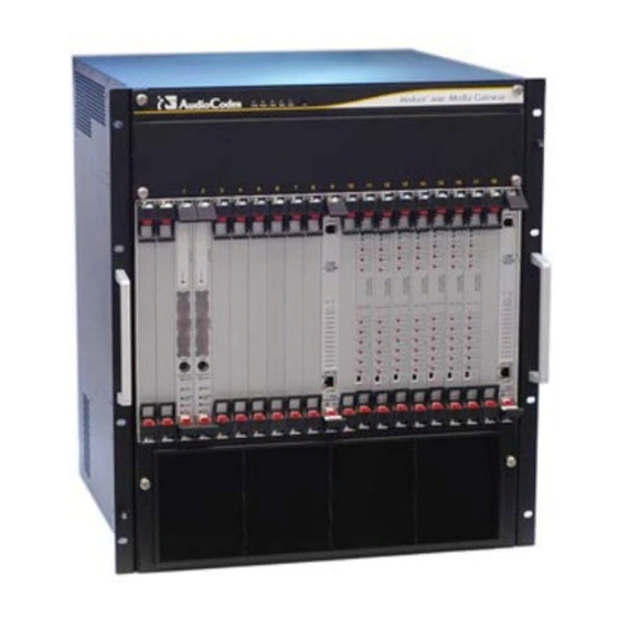
Depending on the ordered configuration, the actual views of your Mediant 8000 may differ from the figures below. For example, you may have different type or number of Media Gateway boards installed. Figure 3-1: Mediant 8000 Front View Version 6.6 October 2014... -
Page 38: Figure 3-2: Mediant 8000 Back View
Mediant 8000 Figure 3-2: Mediant 8000 Back View Installation & Operation Manual Document # LTRT-92224... -
Page 39: The Chassis
Installation & Operation Manual 4. The Chassis The Chassis The Mediant 8000 chassis has a 12U form factor and features 19 slots, occupied by System Controller boards, Ethernet Switch boards, Media Gateway boards and corresponding Rear Transition Modules. The boards are inserted from the front and the back and engage the mid-plane on either side inside the chassis. -
Page 40: Nebs Compliancy
Weight (Fully loaded) 45 kg (99.2 lb) NEBS Compliancy The Mediant 8000 chassis complies with NEBS Level 3 requirements. The unit is compatible with Common Bonding Network (CBN) and Isolated Bonding Network (IBN) installations. The Equipment is compatible with DC-C and DC-I networks. -
Page 41: Power System
Installation & Operation Manual 5. Power System Power System The DC Power System powers the Mediant 8000 from the DC power sources. It consists of the following hardware components: PEM/DC/8K Power Entry Module PS/DC/8K Power Supply Module PEM/DC/8K Power Entry Module PEM/DC/8K Power Entry Modules are used for connecting the Mediant 8000 chassis to the DC power sources. -
Page 42: Ps/Dc/8K Power Supply Module
Maximum allowable voltage should not exceed -60 VDC Provide sufficient capacity for the average power consumption of Mediant 8000 chassis (see 'Electrical Requirements' on page 93) Ensure that power supply complies with the safety requirements of CAN/CSA- C22.2 No. -
Page 43: Cooling System
Air Flow Clean air is drawn in by the fans and passes through the entire set of plug-in front and rear boards residing in the slots, cooling each one. The air exits the Mediant 8000 via perforated vents in the chassis. - Page 44 Mediant 8000 This page is intentionally left blank. Installation & Operation Manual Document # LTRT-92224...
-
Page 45: Alarm Indicators
7. Alarm Indicators Alarm Indicators Chassis Alarm Indicators are located in the front of the Mediant 8000 chassis above the FM/8K Fan Tray Module’s protective cover. They are used to indicate failure conditions on hardware components – e.g. malfunction of the Fan Tray Module or lack of the power input in a Power Supply. - Page 46 Mediant 8000 This page is intentionally left blank. Installation & Operation Manual Document # LTRT-92224...
-
Page 47: Tp-6310 Media Gateway Board
Installation & Operation Manual 8. TP-6310 Media Gateway Board TP-6310 Media Gateway Board The TP-6310 board is a high-density, hot-swappable resource board with a capacity of up to 2016 DS0 channels, supporting all necessary functions for voice, data and fax streaming over IP networks. -
Page 48: Table 8-1: Tp-6310 Board Status Led Indicators
Note: There is an unmarked pinhole on the front panel of the TP-6310 board. This pinhole should never be used when the TP-6310 is inserted into the Mediant 8000 chassis. The TP-6310 Media Gateway board has LED indicators on its front panel that are used to indicate status of the board and of its PSTN interfaces. -
Page 49: 6310/Rtm - Rear Transition Module
Installation & Operation Manual 9. 6310/RTM - Rear Transition Module 6310/RTM - Rear Transition Module The 6310/RTM Rear Transition Module is a hot-swappable rear module that provides PSTN connectivity for TP-6310 Media Gateway board. It is installed in the rear side of the chassis behind the corresponding TP-6310 board and features the following interfaces: ... -
Page 50: Figure 9-1: 6310 Rtm Front Panel
Mediant 8000 Figure 9-1: 6310 RTM Front Panel Note: The unused SFP receptacles must be covered with dust covers. Installation & Operation Manual Document # LTRT-92224... -
Page 51: 6310/Rtm Redundant
Installation & Operation Manual 9. 6310/RTM - Rear Transition Module 6310/RTM Redundant The TP-6310 board that is configured as a redundant board must be accompanied by a proper Redundant RTM module. The latter has no connectors on it and is used for routing PSTN links from the failed TP-6310 board to the redundant board. - Page 52 Mediant 8000 This page is intentionally left blank. Installation & Operation Manual Document # LTRT-92224...
-
Page 53: Tp-8410 Media Gateway Board
Installation & Operation Manual 10. TP-8410 Media Gateway Board TP-8410 Media Gateway Board The TP-8410 board is a high-density, hot-swappable resource board with a capacity of up to 2016 VoP channels, supporting all necessary functions for voice, data and fax streaming over IP networks. -
Page 54: Table 10-1: Tp-8410 Board Leds
Mediant 8000 Note: There is an unmarked pinhole on the front panel of the TP-8410 board. This pinhole should never be used when the TP-8410 board is inserted into the Mediant 8000 chassis. The TP-8410 Media Gateway board has LED indicators on its front panel that are used to indicate the status of the board and its PSTN interfaces. -
Page 55: Led Array Display
Installation & Operation Manual 10. TP-8410 Media Gateway Board LED Label Description Color Board Power is down SWAP READY Normal Operation Board is ready to be extracted Blue from the chassis (latch is open) 10.1 LED Array Display The LED Array display indicates the trunk numbers currently represented by the TP- 8410 board's PSTN LEDs (labeled E1/T1). - Page 56 Mediant 8000 This page is intentionally left blank. Installation & Operation Manual Document # LTRT-92224...
-
Page 57: 8410/Rtm Rear Transition Module
Installation & Operation Manual 11. 8410/RTM Rear Transition Module 8410/RTM Rear Transition Module The 8410/RTM Rear Transition Module is a hot-swappable rear module that provides PSTN connectivity for the TP-8410 Media Gateway board. It is installed in the rear side of the chassis behind the corresponding TP-8410 board and features two SCSI connectors (100-Pin and 68-Pin) that are used for connecting up to 42 DS1 (E1/T1) trunks. -
Page 58: 8410/Rtm E1/T1 Trunk Connectors
Mediant 8000 Note: The unused SFP receptacles are covered with dust covers. 11.1 8410/RTM E1/T1 Trunk Connectors The 8410/RTM provides two SCSI connectors that are used for connecting up to 42 E1/T1 trunks: 100-pin female connector-used for connecting trunks 1-25 ... -
Page 59: Figure 11-3: 8410/Rtm 68-Pin Scsi Connector
Installation & Operation Manual 11. 8410/RTM Rear Transition Module E1/T1 Number (1 to 25) Tx Pins Rx Pins (Tip/Ring) (Tip/Ring) RTM-8410 24/23 74/73 26/25 76/75 28/27 78/77 30/29 80/79 32/31 82/81 34/33 84/83 36/35 86/85 38/37 88/87 40/39 90/89 42/41 92/91 44/43 94/93... -
Page 60: Table 11-2: 8410/Rtm 68-Pin Scsi Connector
Mediant 8000 The 68-pin female SCSI connector is shown in the figure above and must mate with a male connector that is wired according to the connector pinouts in the following table. Table 11-2: 8410/RTM 68-pin SCSI Connector E1/T1 Number (26 to 42) -
Page 61: 8410/Rtm Redundant
Installation & Operation Manual 11. 8410/RTM Rear Transition Module 11.2 8410/RTM Redundant The TP-8410 board that is configured as a redundant board must be accompanied by a proper Redundant RTM module. The latter has no port connections and is used for routing PSTN E1/T1 trunks from the failed TP-8410 board to the redundant board. - Page 62 Mediant 8000 This page is intentionally left blank. Installation & Operation Manual Document # LTRT-92224...
-
Page 63: System Controller (Sc) Board
System Controller (SC) Board The SC (System Controller) board is a hot-swappable Single Board Computer (SBC). It provides management interface to the Mediant 8000 and is responsible for system configuration, status monitoring and high-availability operation. Two SC boards are provided for high-availability and are installed in slots 1 and 2 (color coded red). -
Page 64: Sc Rev.1 Board (Solaris Os)
Mediant 8000 12.1 SC Rev.1 board (Solaris OS) The SC Rev.1 board is based on the SUN CP2300 SBC and runs the SUN Solaris 9 Figure 12-1: SC Rev.1 Board Panel Installation & Operation Manual Document # LTRT-92224... -
Page 65: Sc Rev.1 Mini Din 8 Com Rs-232 Port
Note: There are two recessed push buttons on the front panel of the SC board, marked ABORT and RESET. These buttons should never be used when the SC board is inserted into the Mediant 8000 chassis. Version 6.6 October 2014... -
Page 66: Sc Rev.2 Board (Linux Os)
Mediant 8000 12.2 SC Rev.2 Board (Linux OS) SC Rev.2 is a next-generation SC board that uses an Intel CPU and runs on the Linux Figure 12-3: SC Rev.2 Board Panel Installation & Operation Manual Document # LTRT-92224... -
Page 67: Sc Rev.2 Rs-232 Serial Port
USB storage devices (e.g. USB Flash Drive or USB CD-ROM) and USB peripherals (e.g. keyboard or mouse) to the SC board. Use of these ports should be limited to the software installation (as described in 'Installing Mediant 8000 Software' on page ) and debugging only. -
Page 68: Status Leds
Mediant 8000 12.2.4 Status LEDs The SC Rev.2 board has LED indicators on its front panel that are used to indicate the status of the board. Table 12-3: SC Rev.2 Board (Linux OS) LED Indicators Label Function Color FAIL Normal operation... -
Page 69: Sa/Rtm Synchronization And Alarm Rear Transition Module
Note: To order the SA/RTM board with a resident Timing Module (SA-1/RTM board), refer to the AudioCodes price list. Two SA/RTM boards are provided for high-availability and installed in the chassis’ rear slots 1 and 2, behind the corresponding SC boards. -
Page 70: Sa/Rtm Rs-232 Console Port
Mediant 8000 The SA/RTM board has LED indicators on its front panel that are used to indicate the status of the board. Table 12-4: SA-RTM LED Indicators Label Function Color FAIL Normal operation Board failure Active board Green Standby board... -
Page 71: Sa/Rtm Terminal Block Connector
Installation & Operation Manual 12. System Controller (SC) Board 12.3.2 SA/RTM Terminal Block Connector The SA/RTM board provides a Terminal Block Connector that may be used for connecting the Telco alarm equipment. Three dry contacts – COM (Common), NO (Normally Open) and NC (Normally Closed) – are provided for each alarm. Table 12-6: SA/RTM Terminal Block Connector Alarm Description... -
Page 72: Built-In Led Interface
Mediant 8000 12.3.3.1 Built-In LED Interface Each SA/RTM BITS Interface has LEDs that indicate its status. Table 12-7: SA/RTM BITS Interface LEDs Label Color Function LED#1 No Signal Green BITS signal – synchronized LED#2 Not in use Installation & Operation Manual... -
Page 73: Ethernet Switch Board
Six of these ports are connected to the ES/6600/RTM module and may be used for connecting the Mediant 8000 to the external IP network. The remainder of the ports are currently not in use. See Section 'ES/6600 Physical Slots to Ethernet Port Mapping' on page for additional details. -
Page 74: Es/6600 Board Panel
Mediant 8000 13.1.1 ES/6600 Board Panel The figure below illustrates the ES/6600 board panel. Figure 13-1: ES/6600 Board Panel Installation & Operation Manual Document # LTRT-92224... -
Page 75: Es/6600 Leds
Installation & Operation Manual 13. Ethernet Switch Board 13.1.2 ES/6600 LEDs The ES/6600 Ethernet Switch board has LED indicators on its front panel that are used to indicate the status of the board and its Ethernet Ports. Table 13-1: ES/6600 Board Status Led Indicators Description Color Code Remarks... -
Page 76: Es/6600 Physical Slots To Ethernet Port Mapping
Mediant 8000 13.1.3 ES/6600 Physical Slots to Ethernet Port Mapping Use the following table to determine which Mediant 8000 physical slot is connected to the specific Ethernet Switch Port. Table 13-2: ES/6600 Physical Front Slots to Ethernet Port Mapping Slot 9 Ethernet... - Page 77 Installation & Operation Manual 13. Ethernet Switch Board Slot 9 Ethernet Slot 19 Ethernet Chassis Slot Dedicated to Board Type Number Switch Port Switch Port Uplink When Interface Separation is disabled, used as the only uplink for the Mediant 8000. When Interface Separation is enabled, used for Media traffic.
-
Page 78: Es/6600/Rtm Rear Transition Module
13.1.4 ES/6600/RTM Rear Transition Module The ES/6600/RTM Rear Transition Module is inserted in the rear Mediant 8000 chassis slots behind the corresponding ES/6600 Ethernet Switch Boards. It provides 10/100/1000Base-T ports that are used for connecting the Mediant 8000 chassis to the external Ethernet equipment. -
Page 79: Table 13-3:Es/6600/Rtm Port Pin Outs
Installation & Operation Manual 13. Ethernet Switch Board Table 13-3:ES/6600/RTM Port Pin Outs Pin Number Signal Name TRDB+ TRDB+ TRDA+ TRDD+ TRDD- TRDA- TRDC+ TRDC- Version 6.6 October 2014... -
Page 80: Es (Ethernet Switch) Board
F-LINK); 10 of these ports are connected to the ES-2/RTM module and may be used for connecting the Mediant 8000 to the external IP network (ports 8 and 9 are not in use). Refer to 'ES-2 Physical Slots to Ethernet Port Mapping' below for additional details. -
Page 81: Es-2 Front Panel
Installation & Operation Manual 13. Ethernet Switch Board 13.2.1 ES-2 Front Panel The figure below illustrates the ES-2 board panel. Figure 13-3: ES-2 Board Panel Version 6.6 October 2014... -
Page 82: Es-2 Leds
Mediant 8000 13.2.2 ES-2 LEDs The ES-2 Ethernet Switch board has LED indicators on its front panel that indicate the status of the board and its Ethernet Ports. Table 13-4: ES-2 Board Status Led Indicators Description Color Code Remarks Currently not in use... -
Page 83: Es-2 Physical Slots To Ethernet Port Mapping
13. Ethernet Switch Board 13.2.3 ES-2 Physical Slots to Ethernet Port Mapping Use the following table to determine which Mediant 8000 physical slot is connected to the specific ethernet switch port. Table 13-5: ES-2 Physical Front Slots to Ethernet Port Mapping... -
Page 84: Table 13-6: Es-2 Physical Rear Slots To Ethernet Port Mapping
Mediant 8000 Use the following table to determine which Mediant 8000 physical rear slot is connected to the specific ethernet switch port according to the specific interface type. Table 13-6: ES-2 Physical Rear Slots to Ethernet Port Mapping Interface Separation... -
Page 85: Es-2 Rtm Rear Transition Module
13.2.4 ES-2 RTM Rear Transition Module The ES-2/RTM (Rear Transition Module) is inserted in the rear Mediant 8000 chassis slots behind the corresponding ES-2 Ethernet Switch boards. It provides 10/100/1000Base-T ports that are used for connecting the Mediant 8000 chassis to the external Ethernet equipment. -
Page 86: Table 13-7: Es-2/Rtm Port Pin Outs
Mediant 8000 Table 13-7: ES-2/RTM Port Pin Outs Pin Number Signal Name TRDB+ TRDB- TRDA+ TRDD+ TRDD- TRDA- TRDC+ TRDC- The following table shows the ES-2 RS-232 Terminal PIN layout. Table 13-8: ES-2 RS-232 Pin Layout Pin Number Signal Name Installation &... -
Page 87: Board Assembly Order
Installation & Operation Manual 14. Board Assembly Order Board Assembly Order For a system configuration with less than the full complement of Media Gateway boards, the board assembly should follow the tables below. Note : The Redundant Media Gateway board must be accompanied with a redundant RTM module. - Page 88 Mediant 8000 This page is intentionally left blank. Installation & Operation Manual Document # LTRT-92224...
-
Page 89: Getting Started
Prepare your site for the Mediant 8000 installation. For more information, see Section 'Site Preparation' on page 91. Install the Mediant 8000 hardware (mount chassis on a rack and power it up). For more information, see Section 'Hardware Installation' on page and 'Powering Up' on page 103. -
Page 91: Site Preparation
Installation & Operation Manual 15. Site Preparation Site Preparation Take the following steps to prepare your site for Mediant 8000 installation: Prepare all needed equipment and cables Verify that your site satisfies the Mediant 8000 electrical and environmental requirements ... -
Page 92: Cables
Mediant 8000 15.2 Cables The following cables are required for proper Mediant 8000 installation. Note : Some of the cables described in this section are not supplied with the system and should be provided by the customer. Table 15-2: Cabling Requirement... -
Page 93: E1/T1 Cables For Tp-8410
Cables (TP-8410 Boards)' on page 58. 15.2.1 E1/T1 Cables for TP-8410 If you use the Mediant 8000 with TP-8410 boards, provide two cables for connecting E1/T1 trunks to each TP-8410 board – one with the 100-pin SCSI connector and another with the 68-pin SCSI connector. -
Page 94: Electrical Requirements
Mediant 8000 15.3 Electrical Requirements The site must satisfy the following electrical requirements for the proper Mediant 8000 installation. Table 15-4: Electrical Requirement Item Requirement Power Feeding In order to maintain the full HA capabilities of the system, a centralized DC power system must be used as specified in UL60950-1, CAN/CSA-C22.2 NO... -
Page 95: Environmental Requirements
15.4 Environmental Requirements The site must satisfy the following environment requirements: The Mediant 8000 complies with the requirements of GR-63-CORE Issue 1 for network switching systems (NEBS) standard . The system operation is guaranteed under the following conditions. Table 15-5: NEBS Requirement... -
Page 96: Preparing The Ip Network Connectivity
15.5 Preparing the IP Network Connectivity The Mediant 8000 must be connected to the IP network for proper operation. The Mediant 8000 may operate in different IP network topologies, including networks with multiple VLANs and subnets. For more information, see Section 'Connecting the... -
Page 97: Allocating Ip Addresses
Allocating IP Addresses Consult with the Network Administrator and allocate the proper IP addresses for all Mediant 8000 components according to the table 'Allocating IP Addresses' below. Ensure that you know the Subnet Mask and Default Gateway for each subnet that will be connected to the Mediant 8000. -
Page 98: Preparing The Pstn Network Connectivity
Prepare the PSTN Network connections that will be used for connecting the Mediant 8000 Gateway to the other PSTN equipment. The PSTN network connection type depends on the type of the Media Gateway boards installed in the Mediant 8000 Gateway: ... -
Page 99: Hardware Installation
Installation & Operation Manual 16. Hardware Installation Hardware Installation Take the following steps to install the Mediant 8000 hardware on the site: Unpack the Mediant 8000 package and verify its content Mount the Mediant 8000 chassis on a rack ... -
Page 100: Mounting The Chassis On A Rack
Mediant 8000 16.2 Mounting the Chassis on a Rack The Mediant 8000 is provided with mounting flanges on either side of the front of the chassis, appropriate for standard 19-inch racks. Rack Mount Safety Instructions (UL) Note: When mounting the chassis on a rack, be sure to implement the following Safety instructions: •... -
Page 101: Figure 16-1: Attaching The Chassis To The Rack
Installation & Operation Manual 16. Hardware Installation While the two people are holding the chassis in place; a third person fastens the chassis to the rack rails using eight screws (not provided), four on each side of the chassis or as appropriate for your rack type. See the figure below. Figure 16-1: Attaching the Chassis to the Rack Version 6.6 October 2014... -
Page 102: Earthing The Chassis
16.3 Earthing the Chassis The Mediant 8000 chassis must be earthed to a stable local earth reference. Both of the chassis earth terminals (located on PEM modules) should be connected through a separate earth wire (4 AWG or better) to the rack's earthing. The earth connection's resistance must not be greater than 0.1 ohm. -
Page 103: Lightning Protection
2kV. 16.5 Powering Up After mounting the chassis and connecting it to the earth, the Mediant 8000 is ready to power up. Note: Prior to connecting the Mediant 8000 to the power supply, verify the following: •... -
Page 104: Connecting The Mediant 8000 To The Dc Power Supply
DC. Each terminal block must be connected to a separate power source to guarantee redundancy of the power main supply. Figure 16-3: Connecting the Mediant 8000 to a DC Power Supply Note: Ensure that the power connections are according to the indicated polarity. -
Page 105: Figure 16-4: Securing The Pem Plastic Cover Spacers (Hex)
Remove the clear protective covers from the terminal blocks. Use two insulated crimp terminal tongues for ¼" stud size for making the connections to the terminal block (supplied with the Mediant 8000). Prepare the two connections using 8 AWG stranded wiring (for more information, see ) and mount them in place paying attention to the polarity. -
Page 106: Figure 16-5: Secure The Pem Plastic Cover Screws
Figure 16-5: Secure the PEM Plastic Cover Screws Note: The plastic covers, spacers and screws are required to fasten the plastic covers are provided in the Mediant 8000 Accessory kit. Installation & Operation Manual Document # LTRT-92224... -
Page 107: Initial Power On
Installation & Operation Manual 16. Hardware Installation 16.5.2 Initial Power On To power on, take this step: Turn on the DC power input by energizing both circuit breakers (set to I). (One is enough to power-up the chassis). Table 16-1: PEM LED Indicator Functional Unit... - Page 108 Mediant 8000 This page is intentionally left blank. Installation & Operation Manual Document # LTRT-92224...
-
Page 109: The Command Line Interface (Cli)
For most configuration and maintenance tasks, you should connect to the CLI interface on the Active SC board. However, for installation and basic configuration of the Mediant 8000 you will have to establish connection with the CLI interface on both SC boards. -
Page 110: Figure 17-1: Using Putty For Rs-232 Serial Connections
Mediant 8000 To connect to the CLI via an RS-232 serial console: Connect the PC or RS-232 Console Terminal via the appropriate RS-232 cable to either the SC’s RS-232 serial port or the serial port on the SA/RTM. If you are using a PC, run the terminal client software and choose the serial port where the RS-232 cable is connected. -
Page 111: Figure 17-2: Putty Rs-232 Serial Connection Settings
Installation & Operation Manual 17. The Command Line Interface (CLI) Figure 17-2: PuTTY RS-232 Serial Connection Settings Version 6.6 October 2014... -
Page 112: Connecting To The Cli Via The Ip Internet Network
17.2 Connecting to the CLI via the IP Internet Network When IP connectivity with the Mediant 8000 is available, use Secure Shell (SSH) or Telnet client to connect to the Mediant 8000 CLI interface. If you wish to connect to the CLI interface on the Active SC board, establish... -
Page 113: Command Line Interface Users
CLI administrators – this group of users should be used for performing regular Mediant 8000 maintenance and configuration tasks; the root user may add new users to this group or remove existing ones. CLI monitors – this group of users should be used for performing status and fault ... -
Page 114: Table 17-2: Command Line Interface Users
CLI administrator acladmin is a default CLI user created acladmin during the Mediant 8000 installation. Use it to perform most maintenance and configuration tasks. Note, however, that the acladmin is a... -
Page 115: Logging Into The Command Line Interface
• The above table shows default passwords of CLI users as defined on SC boards on a new Mediant 8000. For security reasons it is strongly recommended to modify passwords for all CLI users (including root and ems users) prior to field deployment. - Page 116 Mediant 8000 client238::~# su - root Password: ****** Note: Do not omit the "dash" from the su - root command, otherwise root user environment will be improperly set up. Installation & Operation Manual Document # LTRT-92224...
-
Page 117: Connecting To The Ip Network
Installation & Operation Manual 18. Connecting to the IP Network Connecting to the IP Network After powering up the Mediant 8000, you need to connect the Media Gateway to the IP network. Take the following steps to complete this task: ... -
Page 118: Configuring The Basic Ip Network Parameters Of Sc Boards
Note: Failure to perform Basic IP Network Configuration prior to connecting the Mediant 8000 chassis to the external network may result in a disruption of service on other equipment connected to the same IP network, due to possible IP address collision with default/previous configuration of SC boards. - Page 119 Installation & Operation Manual 18. Connecting to the IP Network client238::~# install Found uncompressed Media Gateway installation package... Verify installation package integrity... SC Software Installation & Basic Configuration 1 - Change network configuration. 2 - Install the software. 3 - Change basic configuration. 4 - Copy basic configuration from Active SC.
- Page 120 Mediant 8000 Enter the unique hostname you designate for the SC board. Press Enter. Hostname [client33]: SC1 Enter the unique IP address for the SC board and press Enter. The provisioned address is an "private IP address" of the SC board that may be used for connecting to it even when the Media Gateway software is not running.
-
Page 121: Connecting Ip Network Cables
The Mediant 8000 software by default uses a “single subnet without VLAN tagging” configuration. Therefore two external redundant Layer 3 switches or routers should be connected to port 20 on both the ES RTM modules. Use CAT 5 or better 1Gb Ethernet cables for this connection. - Page 122 Mediant 8000 After you complete the Mediant 8000 software installation and/or basic configuration, see 'Connecting the Media Gateway to the IP Network' on page for detailed instructions on how to perform the advanced IP network configuration (e.g. define interface separation and/or VLAN tagging). As part of this advanced configuration, you may be required to re-connect Ethernet cables from the external Layer 3 switchers or routers to different ES board ports.
-
Page 123: Connecting To The Pstn Network
Installation & Operation Manual 19. Connecting to the PSTN Network Connecting to the PSTN Network The Mediant 8000 features the following interfaces for connecting to the PSTN network: STM-1/OC-3 – provided by TP-6310 boards T3 – provided by the TP-6310 boards ... -
Page 124: Fiber Optic Cables
Mediant 8000 Figure 19-1: SFP Modules and Their Locks 19.1.2 Fiber Optic Cables Twin single-mode fiber optic cables with Dual-LC plug must be connected to the PSTN transceivers 1A and 1B on the 6310/RTM module in the rear of the chassis. For PSTN interface redundancy, it is recommended to connect two STM-1/OC-3 links to each 6310/RTM module. -
Page 125: Connecting The T3 Pstn Interfaces
Installation & Operation Manual 19. Connecting to the PSTN Network 19.2 Connecting the T3 PSTN Interfaces T3/DS-3 PSTN cables are connected to the 6310/RTM module in the rear of the chassis. Three T3/DS-3 interfaces are provided on each 6310/RTM module. Use a proper cable with MOLEX PN: 73100-0255 or the equivalent mini-SMB male connector. - Page 126 Mediant 8000 This page is intentionally left blank. Installation & Operation Manual Document # LTRT-92224...
-
Page 127: Connecting To External Telco Alarm Equipment
Connecting to External Telco Alarm Equipment The Mediant 8000 may be connected to the external Telco alarm equipment via a Terminal Block Connector provided on the SA/RTM module. The alarm outputs are rated for 2A at 30V. A maximum gauge of 20 AWG for standard copper wire may be used. -
Page 128: Figure 20-2: Inverse Logic External Alarm Equipment Connection
Mediant 8000 Figure 20-2: Inverse Logic External Alarm Equipment Connection Plug-in the terminal block into the PCB connector. Installation & Operation Manual Document # LTRT-92224... -
Page 129: Software Installation And Basic Configuration
21.1 Installing the Mediant 8000 Software The Mediant 8000 software is installed on the SC boards located in Slots 1 and 2. The SC boards are responsible for managing all the Mediant 8000 components – including the Media Gateway and the Ethernet Switch boards – and distributing the proper software and configuration files to them. -
Page 130: The Mediant 8000 Installation Package
The "Mediant 5000/Mediant 8000 System Software Installation” CD also contains additional documentation and software utilities. The Mediant 8000 software must be installed on both SC boards, located in Slots 1 and 2 correspondingly. The Software installation consists of the following steps: ... -
Page 131: Transferring The Mediant 8000 Installation Package To The Sc Boards
21.1.2 Transferring the Mediant 8000 Installation Package to the SC Boards Prior to installing the Mediant 8000 software, you must transfer the Mediant 8000 installation file (e.g. tg_6.6.16_linux.install) to both SC boards. Note: When performing the Mediant 8000 software installation or Online Software Upgrade, ensure that you use the correct version of the installation package that matches the hardware revision of the SC boards installed in your chassis. - Page 132 Mediant 8000 Transferring the Installation Package to the SC board via the Command-line SFTP Client Microsoft Windows XP [Version 5.1.2600] © Copyright 1985-2001 Microsoft Corp. C:\> psftp acladmin@10.7.13.91 Using username "acladmin" +-----------------------------------------------------------+ | WARNING: To protect systems from unautorized use...
-
Page 133: Preparing For The Mediant 8000 Software Installation
21. Software Installation and Basic Configuration 21.1.3 Preparing for the Mediant 8000 Software Installation The Mediant 8000 software must be installed on both SC boards, located in Slots 1 and 2 correspondingly. Note: Installation of the new Mediant 8000 software version completely erases all the existing Media Gateway configuration (including all IP network configuration, definitions of the Media Gateway boards and the signaling protocols configuration). -
Page 134: Installing The Mediant 8000 Software On The Sc Board To Operate As The Active Board
Operate as the Active board The following installation instructions are relevant only if you are installing the new version of the Mediant 8000 software on both SC boards and should be performed on the SC board residing in Slot 1. - Page 135 Installation & Operation Manual 21. Software Installation and Basic Configuration When you are prompted if you wish to start the installation, type y and press Enter. The software installation begins. Start installation? (y/n) : y Extract /sc_software.tar installation archive... done Extract /sc_install.pl installation script...
- Page 136 Mediant 8000 System Configuration Keyboard shortcuts: ENTER - leave the default parameter value as is - return to the previous parameter Ctrl-C - abort the configuration script At the Global SC IP Address prompt, type the IP address to be assigned to the Active SC board and used to connect to the Media Gateway’s management...
- Page 137 At the Enable Security prompt, type 1 to enable the Mediant 8000 software to operate in Secure Mode or accept the 0 to leave the Mediant 8000 software in its default mode. .For more information, seeFor more information, see Section Section 'Secure Operation Mode' on page 306.
- Page 138 OS Patches need to be installed on the specific SC board. OS patches installation ensures that the latest operating system’s security and stability fixes are applied. It also ensures that the Mediant 8000 software operates in the same well-defined software environment that was used during the software verification and validation process.
- Page 139 Installation of the OS patches on the SC Rev.1 board (using the Solaris OS) may take a considerable amount of time – up to 1.5 hours. The exact amount of time depends on which previous Mediant 8000 software version was installed on the specific SC board.
-
Page 140: Installing The Mediant 8000 Software On The Sc Board To Operate As The Standby Board
Operate as the Standby Board The following installation instructions apply in one of the following cases: If you install the new version of the Mediant 8000 software on both SC boards (follow these instructions for SC board that resides in Slot 2). ... - Page 141 Installation & Operation Manual 21. Software Installation and Basic Configuration Start installation? (y/n) : y Extract /sc_software.tar installation archive... done Extract /sc_install.pl installation script... done Install SC Software >>> save snmp.conf in /tmp/snmp.conf.prev ... >>> save SNMP++ stack configuration in /tmp/snmp.prev ... (This sequence is abbreviated) After the installation successfully completes extraction of all the software binary components, you are prompted to perform the basic configuration of the SC...
- Page 142 Abort installation via Ctrl-C and re-start it from the beginning (this is the preferred option) • Continue installation as described in 'Installing Mediant 8000 Software on the SC Board to Operate as the Active Board' on page and provide exactly the same values that are currently configured on the Active SC board.
- Page 143 0 (Mediant 8000) Note: If you install the Mediant 8000 software on both SC boards, it is possible that copying the configuration from the Active to the Standby SC boards may fail despite the fact that correct credentials for CLI and root users are provided. If you...
- Page 144 Are you sure (y/n) [y]: y If you are installing the Mediant 8000 software on both SC boards, prior to this installation (on the Standby SC board), you have waited for the SC board to operate as the Active board to complete the reboot process. Reboot both SC boards simultaneously by typing y and pressing Enter on the respective SC board’s CLI interfaces.
- Page 145 CLI user that you used to transfer the installation package (e.g. acladmin). Type the rm tg_6.6.16_linux.install command to remove the Mediant 8000 installation package from the SC board. Replace tg_6.6.16_linux.install with the actual Mediant 8000 software package name.
-
Page 146: Peforming Basic Configuration Of The Mediant 8000 Software
Note: If you performed Mediant 8000 software installation as described in 'Installing Mediant 8000 Software' on page 129, skip this chapter and proceed directly to the chapter 'Starting Mediant 8000 Software' on page 153. The basic configuration of the Mediant 8000 software re-defines some high-level configuration parameters (e.g. -
Page 147: Performing Basic Configuration Of The Mediant 8000 Software On The Sc Board To Operate As The Active Board
When the Mediant 8000 is moved to the new IP network segment (and IP addresses of SC boards must be changed). When the Mediant 8000's Operational mode is changed from non-secure to secure mode (or vice versa) ... - Page 148 Mediant 8000 At the Global SC IP Address prompt, enter the IP address to be assigned to the Active SC board and used to connect to the Media Gateway’s management interface (e.g., from EMS server). Global SC IP address [0.0.0.0]: 10.7.13.90...
- Page 149 21. Software Installation and Basic Configuration At the Enable Security prompt, type 1 to enable the Mediant 8000 software operate in Secure Mode or 0 to leave Mediant 8000 software in its default mode. For more information, see Section 'Secure Operation Mode' on page 306.
-
Page 150: Performing Basic Configuration Of The Mediant 8000 Software On The Sc Board To Operate As The Standby Board
Performing Basic Configuration of the Mediant 8000 Software on the SC Board to Operate as the Standby Board The basic configuration of the Mediant 8000 software on the SC board to operate as the Standby board (in Slot 2) should be performed after completing the basic configuration on the SC board to operate as the Active board (in Slot 1). - Page 151 Installation & Operation Manual 21. Software Installation and Basic Configuration client241::~# install Found uncompressed Audiocodes installation package... Verify installation package integrity... SC Software Installation & Basic Configuration 1 - Change network configuration. 2 - Install the software. 3 - Change basic configuration.
- Page 152 Are you sure (n/y) [y]: y If you are installing the Mediant 8000 software on both SC boards, prior to this installation (on the Standby SC board), you have waited for the SC board to operate as the Active board to complete the reboot process.
-
Page 153: Starting Mediant 8000 Software
SC board in Slot 1. To verify that Mediant 8000 software is up and running on specific SC board: Connect to the CLI interface on the specific SC board. For more information, refer to 'Command Line Interface' on page 107. -
Page 154: Configuring Connectivity With The Ems Server
21.4 Configuring Connectivity with the EMS Server After the Mediant 8000 software on both SC boards is up and running, you must configure connectivity between the Mediant 8000 and the EMS Server. This action is performed by running the command tools ems on the CLI interface of the Active SC board. -
Page 155: Advanced Configuration
22. Advanced Configuration Advanced Configuration Once you have successfully connected the Mediant 8000 to the IP and the PSTN networks, powered it up and established connectivity with EMS management application, you should proceed to the configuration of site-specific features and the Media Gateway applications. - Page 156 Mediant 8000 This page is intentionally left blank. Installation & Operation Manual Document # LTRT-92224...
-
Page 157: Configuring And Operating The Media Gateway (Part 1)
Part III Configuring and Operating the Media Gateway (Part 1) This part describe how to configure and operate the Media Gateway. -
Page 159: Overview
AudioCodes Element Management System (EMS) The Mediant 8000 is typically accompanied by the AudioCodes Element Management System (EMS) that is used for managing the Mediant 8000 Media Gateway. The EMS is a universal standards-compliant feature-rich solution that provides management capability for the full line of AudioCodes' Media Gateway/Server products – both digital and analog. -
Page 160: Snmp Management Interface
23.6 Managed Objects, Administrative and Operational State The operational configuration and status of the Mediant 8000 Media Gateway uses an ITU-T X.730/731 compatible data model. The operational configuration and status of the Mediant 8000 Media Gateway is represented by a set of Managed Objects (MOs), which combine physical and logical resources. -
Page 161: Mo Tree Hierarchy
Installation & Operation Manual 23. Overview 23.6.1 MO Tree Hierarchy All MOs are grouped into an MO Tree that represents the hierarchical relationship between different MOs. The Media Gateway MO is located at the top of MO Tree and represents a Gateway Entity. Figure 23-1: Sample MO Tree Hierarchy Note: The sample MO Tree Hierarchy, shown above, illustrates only a sample... -
Page 162: Lock/Unlock Actions
23.7 Managed Objects (MOs) in the EMS EMS uses status screens to illustrate the Mediant 8000 Managed Objects (MOs). Two types of status screens are available: Graphical status screens – each MO is illustrated by a drawing or an icon which resembles the physical view of the hardware component. -
Page 163: Figure 23-2: Graphical Ems Status Screen
Installation & Operation Manual 23. Overview Figure 23-2: Graphical EMS Status Screen Figure 23-3: Textual EMS Status Screen For easy navigation, the EMS GUI divides MOs into group types. For example all security-related MOs are grouped under the “Security” tab. Version 6.6 October 2014... -
Page 164: Figure 23-4: Navigation Pane And Info Panel In Ems
Mediant 8000 Note: These navigation tabs are used in the EMS GUI for navigation purposes only. They are not represented in SNMP Alarm sources nor in the CLI management interface. To navigate between MOs, first select the MO name in the Navigation pane on the left,... -
Page 165: Modifying The Media Gateway Configuration
Installation & Operation Manual 23. Overview 23.8 Modifying the Media Gateway Configuration Each MO contains multiple attributes that represent different properties of corresponding resource. Each attribute has access permissions (read-write or read- only) that indicate whether specific property may or may not be modified by the user. In addition, read-write attributes have a provisioning type that indicates under which conditions a specific attribute may be modified. -
Page 166: Figure 23-5: Ems Configuration Pane
Mediant 8000 In the settings screen, configure parameters and click Apply to apply the new configuration. Figure 23-5: EMS Configuration Pane Figure 23-6: Example Settings Screen-Trunk Settings Installation & Operation Manual Document # LTRT-92224... -
Page 167: Faults And Alarms Monitoring
Installation & Operation Manual 23. Overview 23.9 Faults and Alarms Monitoring Gateway functionality and service status can be monitored in one of the following ways: Polling the status attributes of corresponding MOs Processing trap notifications issued by the Media Gateway Trap notifications are issued by the Media Gateway when a fault or an event occurs that may affect service provided by the Media Gateway or its specific application. -
Page 168: Table 23-2: Ems-Alarm Severity Color
Mediant 8000 EMS displays both alarms and events in the Alarm Browser by default. Cleared alarms are removed from the Alarm Browser, however, may still be viewed by selecting Faults -> Alarms History in the EMS main menu. Events are never cleared; however,... -
Page 169: Figure 23-8: Mos In The Ems Color-Ccoded According To Their Severity
Installation & Operation Manual 23. Overview Figure 23-8: MOs in the EMS Color-Ccoded according to their Severity Version 6.6 October 2014... -
Page 170: Alarm Throttling
Mediant 8000 EMS color-codes MOs according to their Severity attribute, using a similar logic as for alarms. However it also takes into account the Operational State and Administrative State of the MO. The MOs color-coding is described as follows: Table 23-3: MO Severity Colors in the EMS... -
Page 171: Snmp Management Interface
Installation & Operation Manual 24. SNMP Management Interface SNMP Management Interface The Media Gateway supports Simple Network Management Protocol (SNMP) as a main management interface. SNMP is used by the EMS server to perform configuration, alarms collection and performance monitoring tasks. It may also be used by 3 party standard-compliant SNMP managers to perform alarms collection and performance monitoring tasks. - Page 172 Mediant 8000 The Media Gateways SNMP management interface may operate in one of the following modes: • SNMPv2 – a simple default management mode widely deployed in many closed networks, has a relatively weak security model based on the plain- text read and write community strings and therefore is a security threat for systems connected to the public networks (e.g.
- Page 173 Installation & Operation Manual 24. SNMP Management Interface EMS Privacy Protocol (0-No, 1-DES) At the EMS Privacy Key prompt, enter the Key that will be used to ensure privacy of SNMPv3 messages. EMS Privacy Key [leave unchanged]: ****** If you have chosen the SNMPv2 or SNMPv2+IPSEC mode, you must enter the SNMP Read Community and the SNMP Write Community parameters.
- Page 174 Mediant 8000 A summary of the settings is displayed.You are prompted to Start configuring. To commence the configuration, type y and press Enter. Configuration Summary: Enable IPSec 0 (No) SNMP Mode 0 (SNMPv2) EMS Server IP Address 10.7.6.21 SNMP Read Community...
-
Page 175: Configuring Connectivity Between The Media Gateway And Additional Snmp Managers
Configuring Connectivity between the Media Gateway and Additional SNMP Managers Standard-compliant 3 party SNMP managers (e.g. HP OpenView) may be used to perform the following basic management tasks on the Mediant 8000 Media Gateway: Trap notifications (alarms and events) collection ... - Page 176 Mediant 8000 This page is intentionally left blank. Installation & Operation Manual Document # LTRT-92224...
-
Page 177: Syslog Management Interface
Installation & Operation Manual 25. Syslog Management Interface Syslog Management Interface The Media Gateway supports Syslog as an additional management interface. The Syslog interface may be used by 3 party managers (Syslog servers) for trap notifications (alarms and events) collection. Configuration and performance monitoring tasks are not supported via the Syslog management interface (use the SNMP or CLI interfaces instead). -
Page 178: Configuring Connectivity Between The Media Gateway And The Syslog Server178
Mediant 8000 25.1 Configuring Connectivity between the Media Gateway and the Syslog Server To configure connectivity between the Media Gateway and the Syslog server: Click to access the Media Gateway status screen. In the Navigation pane, click Management and in the Configuration pane click Management Settings;the Management Settings screen is displayed. -
Page 179: Connecting The Media Gateway To The Ip Network
26. Connecting the Media Gateway to the IP Network Connecting the Media Gateway to the IP Network The Mediant 8000 must be connected to one or more IP networks to ensure its normal operation. IP network architectures may strongly differ from one site to another. Separate network segments may be used for carrying different types of the traffic (e.g. -
Page 180: Establishing Connectivity With The Ems Server
'Connecting to the IP Network' on page for details. Connect to the Mediant 8000 CLI interface and run the tools ems command to configure connectivity between the Media Gateway and the EMS server. See 'Configuring Connectivity between the Media Gateway and the EMS Server' on page for details. - Page 181 Installation & Operation Manual 26. Connecting the Media Gateway to the IP Network Login as a CLI user with administrative privileges (e.g. acladmin). For more information, see Section section 'Logging into the Command Line Interface' on page 115. Type the following command to reset the IP network configuration to default: SC-1 -- ~ -- /moGW •...
- Page 182 EMS server and the Mediant 8000, contact the on-site network administrator and verify that the physical network topology and configuration of the external Layer 3 Switches / Routers to which the Mediant 8000 is connected is correct. Installation & Operation Manual...
-
Page 183: Configuring Network Topology
Media traffic – including RTP and RTCP protocols The IP network on site, where the Mediant 8000 is installed, may be configured to either pass all types of the IP traffic via the same network segment (the simplest and default network configuration). -
Page 184: Figure 26-1: Network Subnets
Mediant 8000 In both cases, separation between subnets helps to isolate one type of IP traffic from another, which provides both quality of service (QoS) and security features. For example, users connected to the OAM subnet may not in any possible way examine or affect call control and/or media traffic that flows in the separate subnets. -
Page 185: Use Of Oam, Control And Media Subnets By Mediant 8000 Boards
SNMP traffic between the Mediant 8000 and EMS (or 3 party SNMP managers), as well as SSH traffic used for connecting to the Mediant 8000 CLI interface. Spcecific OAM traffic also passes through the Mediant 8000 boards, located in slots 3-8 and 10-18 – for example, the HTTPS traffic used for connecting to the WEB-based debug interface on the Media Gateway boards. -
Page 186: Configuring Ip Network Interfaces
"WAN" interfaces) is possible via the use of VLAN tagging. See 'Ethernet ports allocation on ES boards' on page for the exact numbers of network interfaces (ES board ports) used for connecting Mediant 8000 to the external network equipment in each network interfaces configuration. Installation & Operation Manual... -
Page 187: Figure 26-2: An Example Of "Two O & Cm" Subnet Configuration
Installation & Operation Manual 26. Connecting the Media Gateway to the IP Network Figure 26-2: An Example of “Two O & CM” Subnet Configuration In order to change the IP Network Interfaces configuration, the Media Gateway must be locked and all service on it must be stopped. The new IP network interfaces configuration is not applied immediately;... -
Page 188: Working With Vlans
Ethernet cable (port), based on the VLAN ID tag in the Ethernet frame. In addition, the Mediant 8000 may be connected to the IP network that uses VLAN tagging for all Ethernet frames transmitted through it – even though subnet separation is achieved via the use of a separate network interface as described in Configuring IP Network Interfaces. -
Page 189: Configuring Vlan Tags For Oam Subnet
Installation & Operation Manual 26. Connecting the Media Gateway to the IP Network Note: When configuring Control and Media Subnets,there is no need to lock/unlock ES boards and then unlock the Media Gateway as described in 'Activating New Network Interfaces Configuration' on page 214. 26.2.5.3 Configuring VLAN Tags for OAM Subnet VLAN tagging for the OAM subnet primarily affects management traffic carried by SC... - Page 190 Mediant 8000 In the Interfaces and VLAN Settings tab, go to the Media And Control Subnets VLAN tags section. buttons to add or remove VLAN tag entries. For each VLAN tag entry, configure VLAN tag ID and corresponding Network Interface.
-
Page 191: Media Link Aggregation
26.2.6 Media Link Aggregation The Mediant 8000 uses 1 Gb Ethernet copper ports for connection to IP networks. When five or more TP-6310 or TP-8410 Media Gateway boards are installed in the chassis, the volume of the generated Media traffic may exceed the capacity of a single 1 Gb Ethernet port. - Page 192 – Layer 3 switch to which the Mediant 8000 is connected (for incoming traffic). Configuration on the next-hop network element – Layer 3 switch – must be "the opposite of" the Mediant 8000 configuration. For example, if the Mediant 8000 is configured to distribute traffic using the Source IP address, the next-hop network element –...
-
Page 193: Link Aggregation Control Protocol
ES boards. ES board. ES board is active Failure of one of the The Mediant 8000 continues to use 2 of 3 aggregated links are up aggregated links on the the 2 ES board as active. -
Page 194: Configuring Media Link Aggregation
Mediant 8000 Initial State Event Taken Action & New State ES board is active Failed link on the 1 Switchover to the 1 ES board (where board returns to service. all aggregated links are up). 2 of 3 aggregated links are up on both ES boards. - Page 195 Installation & Operation Manual 26. Connecting the Media Gateway to the IP Network Provisioning Parameter Name Type Description Type Link Aggregation Enum Online Defines rules for traffic distribution Distribution Rule. across aggregated links. Source MAC, (For ES/6600) Destination MAC, Source XOR Destination MAC, Source IP, Destination IP,...
-
Page 196: Configuring Ip Network Connectivity On Sc Boards
Note: Basic IP Network connectivity on SC boards is typically configured during the Mediant 8000 software installation or initial configuration. There is no need to repeat the configuration, if it has already been completed. Installation & Operation Manual... -
Page 197: Additional Oam Subnet Configuration
In addition to the above-described configuration, the following additional OAM Subnet parameters may be configured on the Mediant 8000. The Mediant 8000 may be configured for two additional OAM (management) subnet segments. For each segment, the following parameters must be configured: ... -
Page 198: Configuring Ip Network Connectivity On Media Gateway Boards
Media Subnets – used to transmit media traffic, e.g. RTP. The Mediant 8000 may be connected to one OAM Subnet, and up to ten Control and Media Subnets. Mixed subnets may be used as well – e.g. a single subnet may be used to transmit both OAM and Control types of traffic. -
Page 199: Configuring Ip Subnets
Interface Enum Online Defines the network interface used to connect OCM, CM, OC, C, M, Mediant 8000 to the OLAN, LAN, WAN, specific IP subnet. Subnet Type Enum Online Defines type of the IP traffic carried by the OAM(0), Media(1), subnet. -
Page 200: Ip Network Profiles
Up to 40 chars. 26.4.2 IP Network Profiles The Mediant 8000 uses the term Network Profile to describe a set of IP network properties (configurations) that may be assigned to one or more Media Gateway board. This set consists of the following: ... -
Page 201: Creating Ip Network Profile
Installation & Operation Manual 26. Connecting the Media Gateway to the IP Network 26.4.2.1 Creating IP Network Profile To define a new Network Profile: Click to access the Media Gateway status screen. In the Navigation pane, select Networking Network Profiles; the Network Profiles list is displayed. -
Page 202: Configuring Media Gateway Board's Ip Addresses
Mediant 8000 26.4.3 Configuring Media Gateway Board’s IP Addresses The Media Gateway board must be configured with IP addresses for each IP subnet included in the Network Profile attached to it. To configure Media Gateway Board’s IP addresses: Click the to access the Media Gateway status screen. -
Page 203: Additional Network Settings
Gateway service, by unlocking the corresponding configuration objects. Note: When the Mediant 8000 wishes to send an IP packet, it scans the static routes table starting from the lowest index; the first entry that matches the IP packet's destination IP address is chosen. Therefore, the order of the entries in the static routes table is very important. -
Page 204: Static Routes For Media Gateway (Tp) Boards
Prefix Length destination entity (for IPv4 addresses this 0-120 is equivalent to subnet mask). When the Mediant 8000 wishes to send an IP packet, it compares the packet's destination address with the Destination IP Address of each available static route using a Destination Prefix Length for XOR operation on both. -
Page 205: Table 26-5: Tp Static Route Properties
Prefix Length destination entity (for IPv4 addresses this 0-128 is equivalent to subnet mask). When the Mediant 8000 wishes to send an IP packet, it compares the packet's destination address with the Destination IP Address of each available static route using a Destination Prefix Length for XOR operation on both. -
Page 206: Quality Of Service
Quality of Service Quality of Service (QoS) features are used in multi-service networks to distribute available (limited) network resources across multiple applications and to guarantee the best applicable service to all of them. The Mediant 8000 supports the following QoS features: ... -
Page 207: Ethernet Frame Priority Header
26.5.2.1 Ethernet Frame Priority Header The Mediant 8000 supports Ethernet frame Priority header as defined in the IEEE 802.1p and 802.1q standards. 3-bit priority value (from 0 to 7) may be assigned to each network service class, applicable to the Mediant 8000 . -
Page 208: Differentiated Services (Diffserv)
RFC 3260 – New Terminology and Clarifications for Diffserv DiffServ utilizes Differentiated Services Field (DS Field) in the IP header to indicate the service level of the corresponding IP packet. The Mediant 8000 supports definition of this DS Field (values from 0 to 63) for each supported network service class. -
Page 209: Table 26-8: Network Profile Quality Of Service Settings
Installation & Operation Manual 26. Connecting the Media Gateway to the IP Network Parameter Name Type Provisioning Type Description Bronze Service Class Integer Online Defines Layer 3 Quality Diff Serv 0 – 63 Of Service for Network service class, applied to management traffic. -
Page 210: Configuring Ipv6
4, IPv4 (also known as IP and the presently dominant implementation used in the Internet and corporate LANs). The Mediant 8000 currently provides support for IPv6 only in Call Control and Media Subnets. ... -
Page 211: Table 26-9: Media Realm Settings
Installation & Operation Manual 26. Connecting the Media Gateway to the IP Network Table 26-9: Media Realm Settings Parameter Name Type Provisioning Description Type Media Realm Name String Offline Defines textual name of the Media Realm Up to 63 enabling user to easily identify it. chars IPv4 Subnet Integer... -
Page 212: Additional Network Services And Settings
Mediant 8000 26.6 Additional Network Services and Settings The tables below describe additional network settings that may be configured in the Media Gateway or Media Gateway board’s network configuration screens. Table 26-10: Additional Media Gateway Board Network Settings Parameter Provisioning... - Page 213 Installation & Operation Manual 26. Connecting the Media Gateway to the IP Network Parameter Provisioning Type Description Name Type NAT Mode Enum Instant Enables / disables the Network Address Translation Enabled, (NAT) mechanism. Disabled Note: The compare operation that is performed on the IP address is enabled by default and is controlled by the parameter IP Address Translation.
-
Page 214: Activating New Network Interfaces Configuration
Mediant 8000 26.6.1 Activating New Network Interfaces Configuration The new IP network configuration is activated by unlocking all relevant entities (e.g. Media Gateway, Media Gateway boards) etc. To simplify the network configuration, all "intermediate" configuration objects (e.g. Subnet and Network Profiles) do not require an explicit unlock –... -
Page 215: Offline Network Configuration Of Es-2
The rest of the Media Gateway entities remain unlocked and continue to provide the service. The following examples demonstrate the online network configuration capabilities of the Mediant 8000: Changing the IP address of the specific IP subnet – only the Media Gateway boards, attached to the specific IP subnet are affected. -
Page 216: Activating Offline Network Configuration
Note: After applying the new IP network configuration, connectivity between the Mediant 8000 and the EMS server may be lost, due to the changes in interface separation configuration and consequent changes in the ES board’s Ethernet ports allocation. If such a change occurs, connectivity will be lost as soon as you unlock the 2 ES board. -
Page 217: Connecting The Mediant 8000 To The Ip Network
26. Connecting the Media Gateway to the IP Network 26.7 Connecting the Mediant 8000 to the IP Network After completing the new network configuration and activating it, re-connect the network cables to the appropriate ES board’s Ethernet ports and/or connect additional cables to match the configured interface separation as described in 'Configuring Network Topology' on page 182. - Page 218 Mediant 8000 Interface Separation ES boards Ports Allocation Two: OLAN & WAN Use Port 20 for connection to the LAN network, that carries OAM (management), Call Control and Media traffic. Use Port 22 for connection to the WAN network, that carries Call Control and Media traffic.
-
Page 219: Ethernet Ports Allocation On Es-2-Single Boards
Installation & Operation Manual 26. Connecting the Media Gateway to the IP Network 26.7.2 Ethernet Ports Allocation on ES-2-SINGLE boards Each ES board features nine 1Gb Ethernet copper ports, available on the corresponding ES-2 /RTM board, located in the rear of the chassis. Use of the Ethernet Ports depends on the configured interface separation as described in 'Configuring IP Network Interfaces'. - Page 220 Mediant 8000 Interface Separation ES boards Ports Allocation Three: O & LAN & WAN Use Port 1 for connection to the OAM (management) network. Use Port 2 for connection to the LAN network, that carries Call Control and Media traffic.
-
Page 221: External Layer 3 Ethernet Switches Or Routers
External Layer 3 Ethernet Switches or Routers At least two external fully-redundant Layer 3 ethernet switches or routers are required for connecting the Mediant 8000 to the IP network. Note: When multiple physically-separated subnets are used, it is possible to either use the same properly-configured external Layer 3 switch for multiple subnets or use separate Layer 3 switches for each subnet. -
Page 222: Configuring Hsrp/Vrrp Protocols On External Layer 3 Switches
26.7.3.2 Configuring the Mediant 8000 for the HSRP Protocol When the Mediant 8000 is connected to the Layer 3 switches clustered via the HSRP protocol, configure Media ARP Cache Override parameter to Enable GARP in the Media Gateway board’s Network Settings configuration screen. This setting ensures that Media Gateway board’s ARP cache is updated only when Gratitious ARP packets... -
Page 223: Working With The Sc Boards
SC boards do not participate in VoP (call control and media) traffic, handled by the TP-6310 and the TP-8410 Media Gateway boards. Instead they operate as a “host” of the Mediant 8000 chassis, managing the configuration of all chassis elements (including Media Gateway boards), constantly monitoring the health status of all hardware components and reporting any malfunction to the management stations. -
Page 224: Sc Boards In The Ems
Mediant 8000 27.2 SC Boards in the EMS In the EMS, the Active SC board is colored black, while the Standby SC board is colored blue-gray. The SC board in slot 1 is initially the Active SC board (upon chassis power up) and the SC board in slot 2 is initially the Standby SC board. -
Page 225: Sc Board Actions
Installation & Operation Manual 27. Working with the SC Boards 27.3 SC Board Actions The following actions can be performed on an SC board and are available in the EMS when you right-Click the specific SC board in the Media Gateway status screen: Switchover –... -
Page 226: The Operating System On The Sc Boards
OS configuration is modified. All relevant OS security and bug fixes are delivered as part of the Mediant 8000 software installation package. See 'Installing Mediant 8000 Software' on page 'Online Software Upgrade' on page for details. -
Page 227: Installing The Solaris Os On The Sc Rev.1 Board
27.6.1 Verifying the Current Version of the Solaris OS on the SC Board Version 6.6 of the Mediant 8000 software requires the SUN Solaris 9 ™ version 9/04 or later. To access the current version of the Solaris™ OS: Connect to the SC board's CLI Interface. -
Page 228: Installation Requirements
AudioCodes recommends using the EMS server as the Install server. Note: The Install server must reside on the same LAN subnet as the Mediant 8000 (i.e., it must be connected to the same Ethernet Switch). The installation is to be performed on the SC board while it resides in the Mediant 8000 chassis. -
Page 229: Installing The Solaris 9 Os On The Sc Board
Installation & Operation Manual 27. Working with the SC Boards Note: For correct Install server operation, the following services must be enabled on • TFTP • RARP • BOOTPARAMS • TIME If you use the EMS server as the Install server, login to the EMS server and in the EMS Server Manager, choose the option “Enable Jumpstart Server”... - Page 230 Mediant 8000 Login to the Install server (EMS) as the root user via Telnet, SSH or X-terminal (when connecting to the EMS server, you may need to login as acems user first, and then switch to root user via the su – root command).
-
Page 231: Installing The Linux Os On The Sc Rev.2 Board
27.7.1 Verifying the Current Version of the Linux OS on the SC Board Version 6.6 of the Mediant 8000 software requires the Linux OS version 5.3 or later. To access the current version of the Linux™OS: Connect to the SC board's CLI interface. For more information, see Section 'Command Line Interface' on page 107. -
Page 232: Linux Os Installation Requirements
Mediant 8000 27.7.2 Linux OS Installation Requirements The Mediant 8000 software supports four different mechanisms for Linux OS (re)installation. The following table provides a summary of each available option, its applicability and installation requirements. The options are listed in a descending preference order. -
Page 233: Re-Installing The Linux Os Via The Remote Network Connection
Installation & Operation Manual 27. Working with the SC Boards OS Installation Installation Summary Installation Requirements Mechanism OS installation from the The OS is installed from a bootable USB CD-ROM drive (to be USB CD/DVD drive via "Linux OS for SC boards" CD-ROM to provided by the customer) is the RS-232 console be inserted into the USB CD/DVD... - Page 234 Mediant 8000 When prompted to proceed with the Linux OS re-installation, type y and press Enter. Do you wish to proceed with Linux OS re-installation? (y/n) : y The current IP network configuration is displayed. This configuration is preserved after the Linux OS re-installation. Verify that the configuration is correct and type y and press Enter to proceed with the re-installation.
-
Page 235: Re-Installing The Linux Os Via The Rs-232 Serial Console
Restart the SC board by pressing the hidden “Reset” pin, located on the SC board’s front panel or by extracting and re-inserting the SC board into the Mediant 8000 chassis slot. When the GRUB menu is displayed, press the Space key to pause the boot process. - Page 236 Mediant 8000 Booting 'Re-install Linux OS' root (hd0,0) Filesystem type is ext2fs, partition type 0x83 lock cat /INSTALL/reinstall.txt • W A R N I N G ! ! ! You are going to re-install Linux OS on the SC board.
- Page 237 Installation & Operation Manual 27. Working with the SC Boards When the re-installation has completed, the SC board will be rebooted. After the Linux OS re-installation via the RS-232 console, the SC board will be inaccessible from the IP network (it will be assigned a non-routable local link IP address) and only the following default users with default passwords will be defined on it: Default Username...
-
Page 238: Console
Mediant 8000 When prompted to apply the new network configuration, type y and press Enter. Apply new configuration? ([y]/n) : y SC board must be rebooted to activate the new network configuration. Reboot now? ([y]/n) : y The SC board will be rebooted and will become accessible via the IP network. -
Page 239: Figure 27-2: Format New Volume
Installation & Operation Manual 27. Working with the SC Boards Choose FAT or FAT32 File System and press Start to start the formatting. Figure 27-2: Format New Volume When the formatting has completed, insert “Linux OS for SC Board” CD-ROM into the CD/DVD drive on your Windows PC. -
Page 240: Figure 27-3: Iso2Usb
Mediant 8000 Open the iso2usb folder and run iso2usb.exe file by double-clicking on it. Figure 27-3: ISO2USB Click the “CD Disk” radio button and choose the drive letter that corresponds to the CD/DVD drive where “Linux OS for SC Board” CD-ROM is inserted. -
Page 241: Installing From The Usb Flash Drive
Restart the SC board by pressing the hidden “Reset” pin, located on the SC board’s front panel or by extracting and re-inserting the SC board into the Mediant 8000 chassis slot. The SC board will boot from the USB Flash Drive and display an OS installation welcome screen. - Page 242 Mediant 8000 +-------------+ Error downloading kickstart file +-------------+ | Unable to download the kickstart file. Please modify the | kickstart parameter below or press Cancel to proceed as an | interactive installation. | hd:sdb1:/custom/ks-cd.cfg___________________________________ | +----+ +--------+ | OK |...
- Page 243 Installation & Operation Manual 27. Working with the SC Boards Therefore, you must use the following procedure to change the default user passwords and make the SC board accessible via the IP network by configuring the basic SC board’s network parameters. ...
-
Page 244: Installing The Linux Os From The Usb Cd/Dvd Drive Via The
Mediant 8000 When prompted to apply the new network configuration, type y and press Enter. Apply new configuration? ([y]/n) : y SC board must be rebooted to activate the new network configuration. Reboot now? ([y]/n) : y The SC board will be rebooted and will become accessible via the IP network. -
Page 245: Working With The Media Gateway Boards (Tp-6310 And Tp-8410)
There is an unmarked pinhole on the front panel of the Media Gateway board. This pinhole should never be used when the Media Gateway board is inserted into the Mediant 8000 chassis. In particular, this pinhole should never be used to simulate the Media Gateway board failure/switchover (since switchover may not be properly performed upon such hardware misuse). -
Page 246: Media Gateway Boards In The Ems
Mediant 8000 28.2 Media Gateway Boards in the EMS In the EMS, an Active Media Gateway board is colored black, while the Redundant Media Gateway board is colored blue-grey. Figure 28-1: Media Gateway Boards in the EMS The status of the Media Gateway boards is represented by standard Operational State, Administrative State and Severity attributes. -
Page 247: Hardware And Application Types
Installation & Operation Manual 28. Working with the Media Gateway Boards (TP-6310 and TP-8410) 28.3 Hardware and Application Types The capabilities of the Media Gateway board are defined according to two parameters that must be specified at the time when the new board is defined (via AddBoard action): ... - Page 248 Mediant 8000 • An optional timeout parameter allows the performance of a Graceful Lock on a Media Gateway board – in this case, calls are not torn down immediately; however, the Media Gateway Controller (MGC) or remote SIP agent are informed that the Media Gateway board is to be closed within a specified timeout period.
-
Page 249: The Redundancy Model
Installation & Operation Manual 28. Working with the Media Gateway Boards (TP-6310 and TP-8410) 28.5 The Redundancy Model Media Gateway boards are grouped into Redundancy Groups. Each redundancy group has a dedicated redundant board (equipped with a redundant RTM module) that provides hot redundancy protection for the active boards within the group. -
Page 250: Redundancy Modes
Mediant 8000 28.5.2 Redundancy Modes Each Media Gateway board may have different levels of protection, depending on the configuration of the Redundancy Group that it is assigned to and the configuration of the board itself. The following levels of protection (also called "Redundancy Modes" or "HA Modes") -
Page 251: Desired Redundancy Mode
Installation & Operation Manual 28. Working with the Media Gateway Boards (TP-6310 and TP-8410) 28.5.3 Desired Redundancy Mode Desired Redundancy Mode determines the highest level of protection requested by the user. The Desired Redundancy Mode may be configured for the Redundancy Group (and thus affect all Media Gateway boards associated with the specific group) or for each specific Media Gateway board. -
Page 252: Actual Redundancy Mode
Mediant 8000 28.5.4 Actual Redundancy Mode The Actual Redundancy mode indicates the actual level of protection provided for the specific Media Gateway board. The Actual Redundancy mode may provide a lower level of redundancy to the Desired Redundancy mode, configured by the user, due to the following factors: •... -
Page 253: Figure 28-2: Board Redundancy Status
Installation & Operation Manual 28. Working with the Media Gateway Boards (TP-6310 and TP-8410) It is recommended that you periodically inspect the value of the Actual Redundancy mode for all Media Gateway boards to ensure that the system is configured to provide proper protection in case of board failure. -
Page 254: Activity Switchover
Mediant 8000 28.5.5 Activity Switchover When a failure occurs on the Media Gateway board, one of the following actions are performed: If the Redundant Media Gateway board is available, activity switchover to the Redundant board is performed and service is restored on it. The failed board is not automatically restarted until you explicitly perform an Unlock action on it. -
Page 255: Multiple Redundancy Groups
Installation & Operation Manual 28. Working with the Media Gateway Boards (TP-6310 and TP-8410) 28.5.6 Multiple Redundancy Groups Multiple redundancy groups may be used to provide adequate protection in the following cases: Media Gateway boards installed in the chassis have different hardware or application types. -
Page 256: Table 28-1: Redundancy Group Parameters
Mediant 8000 Table 28-1: Redundancy Group Parameters Provisioning Parameter Name Type Description Type Redundancy Enum Instant Defines the Desired Redundancy mode Mode for all Media Gateway boards assigned to Not Protected, this group. Hot, Warm The Actual Redundancy mode for... -
Page 257: Table 28-2: Media Gateway Board Redundancy Parameters
Installation & Operation Manual 28. Working with the Media Gateway Boards (TP-6310 and TP-8410) Provisioning Parameter Name Type Description Type mode set to Hot. Redundancy Safe Normal – normal detection time ExtraSafe – detection time of board failure is longer; however, false detections (e.g. -
Page 258: Automatic Switchback
Mediant 8000 28.5.7 Automatic Switchback The Media Gateway may be configured to perform automatic activity switchback from the Redundant Media Gateway board back to the failed board, as soon as the later returns to service. This configuration reduces the manual workload performed by the operator upon the Media Gateway board switchover. -
Page 259: Updating License Key
(e.g., to increase the amount of available MTP2 SS7 links). To upgrade the License Key, contact your AudioCodes Account Team and provide detailed information on the specific new features that you wish to activate. You will receive a License Key file that contains licenses for one or more Media Gateway boards. - Page 260 Mediant 8000 Click the button to access the Media Gateway status screen. Right-Click the desired Media Gateway board and from the popup menu, select Maintenance> License Keys Update. Select the License Key file as added in step 1. Lock and unlock the Media Gateway board. The newly added License Key file is applied.
-
Page 261: Working With The Es Boards
29. Working with the ES Boards Working with the ES Boards The Ethernet Switch (ES) boards provide IP network connectivity for all of the boards inside the Mediant 8000 chassis (i.e., the SC and Media Gateway boards. 29.1 ES Redundancy Mode There are two ES boards in the chassis. -
Page 262: Es Board Actions - Es/6600
Mediant 8000 When ES board is not functioning properly (or is absent), its Operational State is set to Disabled and in the EMS, the ES board is colored red. When ES board is locked, its Administrative State is set to Locked and in the ... -
Page 263: Configuring And Operating The Media Gateway (Part 2)
Part IV Configuring and Operating the Media Gateway (Part 2) This part describes the configuration and operation of the Media Gateway. -
Page 265: Time And Date Configuration
Software Logs' on page for details. The Mediant 8000 Media Gateway lacks a hardware clock that is precise enough and can survive a chassis power down/up cycle. Therefore, Network Time Protocol (NTP) is used to synchronize the time and date of the Media Gateway (and all its components) with the external NTP servers. -
Page 266: Using The Ems Server As The Ntp Server
Mediant 8000 30.2 Using the EMS Server as the NTP Server By default, the Media Gateway software uses the EMS server as a pre-configured NTP server and consequently synchronizes it’s time and date with it. The EMS server is pre-configured to operate as an NTP server and no additional configuration is required. -
Page 267: External Ntp Servers Setup - Option 1
Installation & Operation Manual 30. Time and Date Configuration Notes: • If you configure external NTP servers on both the Media Gateway and the EMS server, then you should configure the same NTP servers on both the EMS server and the Media Gateway. •... -
Page 268: External Ntp Servers Setup - Option 2
Mediant 8000 30.3.2 External NTP Servers Setup - Option 2 In the Setup Option 2 below, the EMS server uses two Stratum-2 NTP servers as its NTP clock source and the Media Gateway also uses two Stratum-2 NTP servers as its NTP clock source. -
Page 269: Ntp Synchronization And Status
Installation & Operation Manual 30. Time and Date Configuration 30.4 NTP Synchronization and Status The Media Gateway synchronizes with the NTP server and updates the Operational State and NTP Server Status attributes accordingly. The Operational State attribute indicates whether communication is established with a specific NTP server, while the NTP Server Status attribute indicates the “current status”... -
Page 270: Internal Ntp Implementation
Mediant 8000 30.5 Internal NTP Implementation The following figure illustrates the internal implementation of the time and date synchronization service inside the Media Gateway chassis. Note the following: SC boards operate as NTP clients towards external NTP servers and the EMS server. -
Page 271: Configuring Ntp Servers
Installation & Operation Manual 30. Time and Date Configuration 30.6 Configuring NTP Servers This section describes how to configure the NTP servers. To configure the NTP server: Click to access the Media Gateway status screen. In the Navigation pane, select Time and Date NTP Servers;... - Page 272 Mediant 8000 Parameter Name Type Provisioning Description Type Prefer Mode ENUM – yes/no Online Prefer this NTP Server to others. NTP Version INTEGER 3-4 Read-Only NTP Version number to be used for outgoing NTP packets. Default=4 Installation & Operation Manual...
-
Page 273: Viewing Ntp Servers' Status
Installation & Operation Manual 30. Time and Date Configuration 30.7 Viewing NTP Servers' Status To view NTP servers' status: Click the button to access the Media Gateway status screen. In the Navigation pane, select Time And Date NTP Servers; the NTP Servers list is displayed. - Page 274 Mediant 8000 Parameter Name Type Provisioning Description Type Administrative Enum Read-Only Determines whether the Media Gateway State uses a specific NTP Server as a Locked, Unlocked synchronization source . If locked, the specific NTP Server is not used for time and date synchronization.
- Page 275 Installation & Operation Manual 30. Time and Date Configuration Parameter Name Type Provisioning Description Type Reference String Read-Only Local time, in timestamp format, when the Timestamp local clock was last updated. If the local clock has never been synchronized, the value is zero.
- Page 276 Mediant 8000 This page is intentionally left blank. Installation & Operation Manual Document # LTRT-92224...
-
Page 277: Configuring The Mgcp/Megaco Protocols
31.1 Media Gateway Controller The Mediant 8000 can communicate with a number of Media Gateway Controllers / Call Agents via MGCP/MEGACO protocols. In the EMS, each Media Gateway Controller (MGC) is represented by a MGC entity, in which a set of IP addresses and call control protocol parameters are defined. -
Page 278: Mgcp Control Protocol
Mediant 8000 To configure the basic Media Gateway Controller parameters: Click to access the Media Gateway status screen. Select the specific Media Gateway board. In the Navigation pane, select Call Control MGCs; the MGCs list is displayed. Use the buttons to add or remove entries. -
Page 279: Media Gateway Controller Addressing
Installation & Operation Manual 31. Configuring the MGCP/MEGACO Protocols 31.4 Media Gateway Controller Addressing There are two alternative methodologies for addressing the MGC: via FQDN name via IP addresses 31.4.1 Via FQDN Name When the MGC is addressed via FQDN name, the FQDN is resolved to the IP address through the DNS server. -
Page 280: Endpoint Name Provisioning
Mediant 8000 31.5 Endpoint Name Provisioning This section describes the endpoint name provisioning. 31.5.1 Physical Terminations The Physical Terminations are provisioned via the Phys Term Name Pattern parameter that contains the Endpoint Name template. Indexes (e.g. Board#, Trunk# and Channel#) are indicated in the template by * (asterisk) character. The exact... -
Page 281: Ephemeral Terminations (For Megaco Only)
Installation & Operation Manual 31. Configuring the MGCP/MEGACO Protocols 31.5.2 Ephemeral Terminations (for MEGACO only) Ephemeral Terminations are provisioned via the MEGACO RTP Term Name Pattern parameter. Indexes (Board# and Termination#) are indicated in template by the * (asterisk) character. At least one * characters should be present in the template –... -
Page 282: Domain Name Provisioning
31.7 MEGACO Virtual Gateways The Mediant 8000 supports MEGACO Virtual Gateway functionality, as defined in the H.248.1 spec, section 11.1 “Multiple Virtual MGs”. Each Media Gateway board may be divided into up to three virtual gateways (VGWs). Each virtual gateway registers and operates autonomously with its own controlling MGC(s). -
Page 283: Configuring Mgcp/Megaco Call Control Settings
Installation & Operation Manual 31. Configuring the MGCP/MEGACO Protocols 31.8 Configuring MGCP/MEGACO Call Control Settings To configure MGCP/MEGACO Call Control settings, perform the following tasks: Configure Virtual Gateways (if applicable) Configure Media Gateway Controllers Associate Media Gateway Controllers with Media Gateway Boards and/or Virtual Gateways ... - Page 284 Mediant 8000 Provisioning Parameter Name Type Description Type Network Subnet Integer Online Defines index of the Network Subnet to be used for communication with the specific 0 – 10 Virtual Gateway. Default value 0 means that the first Control Subnet will be used.
-
Page 285: Configuring Media Gateway Controller
Defines the call control protocol type None, (MEGACO, MGCP). MEGACO, MGCP MEGACO Check Enum Instant Defines whether the Mediant 8000 rejects MGC Legality Disabled, MEGACO commands from an MGC with an IP address not included in the provisioned list Enabled MGCP Version String Online Defines the MGCP protocol version. -
Page 286: Table 31-4: Media Gateway Controller Addressing Parameters
Mediant 8000 Provisioning Parameter Name Type Description Type Referenced By String Read-only Indicates all the Media Gateway boards associated with this Media Gateway Up to 255 Controller. chars Table 31-4: Media Gateway Controller Addressing Parameters Provisioning Parameter Name Type Description... -
Page 287: Table 31-6: Mgc Ip/Fqdn Address Parameters
Installation & Operation Manual 31. Configuring the MGCP/MEGACO Protocols Provisioning Parameter Name Type Description Type MEGACO RTP Integer Online Defines the offset to be used in the MEGACO Term Offset RTP terminations. 0 – 2147483647 To configure the Media Gateway Controller’s IP/FQDN addresses: Click to access the Media Gateway status screen. -
Page 288: Associating Media Gateway Controller With Media Gateway Boards
Mediant 8000 Provisioning Parameter Name Type Description Type with lower Activity Number have higher priority. IP address with highest priority will be used as Primary IP, and the rest - as redundant IPs. Virtual GW Index Integer Online Defines the index of Virtual GW, that this 1 –... -
Page 289: Configuring Additional Mgcp/Megaco Settings
Installation & Operation Manual 31. Configuring the MGCP/MEGACO Protocols 31.8.4 Configuring Additional MGCP/MEGACO Settings This section describes how to configure additional MGCP/MEGACO Settings. To configure additional MGCP/MEGACO Settings: Click to access the Media Gateway status screen. Select the Media Gateway board. In the Navigation pane, select Call Control and then in the configuration pane, click Call Control Settings;... - Page 290 Mediant 8000 Provisioning Parameter Name Type Description Type SDP Behavior Integer Instant Defines a bitmap that determines SDP 0 – processing capabilities. 2147483647 RFC3407, Simple Capabilities support V.152, VBD Support Support FRC Strict Negotiation T,S,O Line Display ...
- Page 291 Installation & Operation Manual 31. Configuring the MGCP/MEGACO Protocols Provisioning Parameter Name Type Description Type MGCP Timeout - Integer Instant Defines the MGCP timeout for the first 1st ReTx 50 – 1000 retransmission (in msec). The retransmission intervals thereafter increase exponentially. MGCP Comm Integer Instant...
- Page 292 Mediant 8000 This page is intentionally left blank. Installation & Operation Manual Document # LTRT-92224...
-
Page 293: V5.2 Access Gateway
H.248 IP protocol and then hands them off to a softswitch and vice versa. The gateway and the softswitch may be used as a replacement for traditional Class 5 PSTN switch. The V5.2 Access Gateway application implemented on the Mediant 8000 has the following capabilities: ... -
Page 294: Working With The V5.2 Access Gateway
secondary signaling V5.2 links; applicable only when the Interface's Operational State is "In Service". The Mediant 8000 also performs automatic switchover between signaling links when a problem at the physical or data link layers is detected. However there is no automatic switchback when the failed link recovers. -
Page 295: V5.2 Link Status And Maintenance Actions
32.1.1.3 V5.2 User Ports Status The Mediant 8000 maintains the current V5.2 User Ports configuration in an auxiliary file named SlotX_V52_FILE.csv. The file can be found in auxiliary files repository (refer to 'Auxiliary Files Repository' on page 422) and may be downloaded to your PC and opened in a text or CSV editor to view the current V5.2 User Ports configuration. -
Page 296: Configuring The V5.2 Access Gateway
Mediant 8000 32.1.2 Configuring the V5.2 Access Gateway Perform the following steps to configure the V5.2 Access Gateway application: Configure Media Gateway board's PSTN parameters Configure trunks that carry V5.2 links Configure V5.2 Interfaces Configure V5.2 Links ... -
Page 297: Configuring V5.2 Interfaces
Installation & Operation Manual 32. V5.2 Access Gateway E1 Trunks that carry V5.2 Links must be configured as follows: • Protocol Type = V5(43) • V5.2 Number Of C-channels : for trunks that carry signaling V5.2 links, set the value to 1; otherwise set the value to 0. •... -
Page 298: Configuring V5.2 Links
Mediant 8000 32.1.2.4 Configuring V5.2 Links Add new V5.2 Links voice and signaling links as required. Use Trunks and V5.2 Interfaces defined in the previous steps to complete the V5.2 Links configuration. Ensure that for each V5.2 Interface, two signaling V5.2 Links – primary and secondary –... -
Page 299: Configuring V5.2 User Ports
The configuration file is constructed by the user (typically using a text editor – e.g. Notepad) and applied to the Mediant 8000 via the Download V5.2 Configuration Port File action on the corresponding TP-8410 Media Gateway board. For consistency, it is recommended to use .csv extension for V5.2 User Ports configuration file. - Page 300 Mediant 8000 32.1.2.5.2 Downloading the V5.2 User Ports Configuration File A V5.2 User Ports Configuration file must be uploaded to the EMS Software Manager and then downloaded to the specific TP-8410 Media Gateway board via Download V5.2 Configuration Port File action. You may choose whether the specified V5.2 User Port configuration file is applied as "additional"...
-
Page 301: Bringing V5.2 Interfaces "In Service
Installation & Operation Manual 32. V5.2 Access Gateway Verify the V5.2 User Ports Configuration File download result: When the configuration file is downloaded to the TP-8410 Media Gateway board, an operation status screen is displayed showing the summary of the applied V5.2 User Ports configuration. - Page 302 Mediant 8000 This page is intentionally left blank. Installation & Operation Manual Document # LTRT-92224...
-
Page 303: Configuring Security Settings
To ensure secure operation of the Mediant 8000 take the following steps: Implement security features in the IP network to which the Mediant 8000 is connected (e.g. by limiting physical access to the network and using firewalls). ... -
Page 304: Figure 33-1: Security Features
SRTP provides security for the media traffic. To enable proper Media Gateway operation in a hostile network environment, ensure to implement security features for all applicable Mediant 8000 components (boards), network segments (subnets) and applications. Installation & Operation Manual... -
Page 305: Security Configuration Guidelines
The following guidelines are provided as a starting point for users who wish to implement basic security features on the Mediant 8000 Media Gateway. For a detailed description of each feature and for the additional security features, see the chapters below. -
Page 306: Secure Operation Mode
Mediant 8000 33.2 Secure Operation Mode The Secure Operation Mode must be enabled on the Mediant 8000 Media Gateway as a first step toward a secure configuration and prior to enabling additional security- related features. When the Secure Operation mode is enabled, the following changes are applied to the Media Gateway: ... -
Page 307: Enabling Secure Operation Mode
Perform basic configuration of the Media Gateway software on the SC board in Slot 1, as described in 'Performing Basic Configuration of the Mediant 8000 Software on the SC board to Operate as the Active Board' on page 147. At the Enable Security prompt, choose 1. -
Page 308: Disabling Secure Operation Mode
of IPSEC/IKE with SNMPv3 is not recommended, because SNMPv3 has its own authentication and encryption mechanisms. For secure operation of the Mediant 8000 choose SNMPv2 + IPSEC or SNMPv3 management modes. See 'Configuring Connectivity between Media Gateway and EMS Server' on page for detailed description on how to configure SNMP management mode and establish connectivity with EMS server. -
Page 309: Secure Access To The Cli Interface
33.5 Disabled Remote Root Login The Mediant 8000 does not allow use of root username when logging into the CLI interface via the IP network. This measurement reduces the chances of a successful brute force attack on root super-user account and is considered to be a common practice. -
Page 310: Enabling A Direct Remote Root Login
Mediant 8000 33.5.1 Enabling a Direct Remote Root Login If due to exceptional circumstances, you need to enable remote root login to the specific SC boards, this can be done as follows: Note: Enabled remote root login constitutes a severe security flaw. Therefore you should disable it immediately after completing the specific maintenance task. -
Page 311: Disabling A Direct Remote Root Login
OS Hardening The Mediant 8000 software automatically performs “hardening” of the Operating System on all its boards to minimize the risk of service disruption on any Mediant 8000 component by malicious user (hacker). For SC boards, OS hardening is implemented according to the DoD IASE Security Technical Implementation Guidelines (STIGs) and includes the following: ... -
Page 312: Os Security Patches (On Sc Boards)
OS. OS security patches may be upgraded via one of the following options: By upgrading the Mediant 8000 software to a latest version via the regular Online Software Upgrade procedure – this is the preferred option. ... -
Page 313: Installing Os Security Patches From A Latest Installation Package
Login as root user. For more information, see Section 'Logging in as a Root User' on page 115. Stop the Mediant 8000 software on the Standby SC board, by typing tools sc dn and pressing Enter. When prompted to confirm this command, type y and press Enter. - Page 314 Mediant 8000 tg_6.6.32.install with the name of the latest Mediant 8000 installation package. Don’t forget to specify os_patch as the last command argument. client241::~# install ~acladmin/tg_6.6.32.install os_patch Core Network Media Gateway Version : 6.6.15 OS patches installation WARNING: installation of OS patches may take up to 1 hour and may require reboot of the SC board.
-
Page 315: Installing The Latest Os Security Patches From The "Os Security Patch Bundle
Security Patch Bundle” The “OS security patch bundle” is a special installation package that contains only the latest OS security patches (without the core Mediant 8000 software) and is provided on customer request. Installation of the latest OS security patches from the “OS security patch bundle” is very similar to the procedure described in Installing OS Security Patches from a Latest Version Installation Package’... -
Page 316: File System Integrity
A File System Integrity Check is implemented on SC boards and provides an additional security mechanism that helps to mitigate security risks such as hacker intrusion and malicious software installation. Since all Mediant 8000 software and configuration is stored on the SC boards and then distributed to the corresponding Mediant 8000 components (including Media Gateway and ES boards), implemented integrity measures essentially apply to the Mediant 8000 as a whole. -
Page 317: Table 33-1: Filesystem Integrity Status Parameters
Installation & Operation Manual 33. Configuring Security Settings Table 33-1: Filesystem Integrity Status Parameters Parameter Name Type Provisioning Type Description File System Integrity Enum, Read-only Indicates File System Status Integrity Status. ok/failure Integrity Unauthorized String Read-only When unauthorized Files modifications to the file system are detected, the exact names of the modified files are listed. -
Page 318: Scheduling File System Integrity Check
Mediant 8000 client238::~# tools fs status INTEGRITY CHECKING STATUS Last Integrity Scan: Thu Jan 11 15:09:34 GMT 2007 *** Detected Integrity Violation! *** Affected Files: /etc/hosts - CHANGED /etc/hosts.old - ADDED 33.8.2 Scheduling File System Integrity Check A File System Integrity check is performed on a daily basis. By default, the check is run at 2:00 AM;... -
Page 319: Restoring File System Integrity
Installation & Operation Manual 33. Configuring Security Settings Table 33-2: Filesystem Integrity Configuration Parameters of the Media Gateway Parameter Name Type Provisioning Type Description Integrity Check Time String Instant Time of the day when File System Integrity in HH:MM format Check is performed daily. -
Page 320: Os Auditing On Sc Boards
Mediant 8000 When all files are acknowledged, run File System Integrity Scan by typing tools fs scan and pressing Enter. Wait till the scan completes. client238::~# tools fs scan If all problems are fixed, File System Integrity Status displays OK and the following report is produced. -
Page 321: Os Auditing On The Mediant 8000 Media Gateway
33.9.3 OS Auditing on the Mediant 8000 Media Gateway When the Mediant 8000 Media Gateway software is installed on the SC boards, it automatically configures the OS auditing subsystem to record the most important security-related activity on the SC board. The list of recorded events complies with DoD IASE STIG and GR-815 security requirements. - Page 322 Mediant 8000 client238::~# aureport—summary Summary Report Range of time in logs: 07/30/2009 02:40:01.533 - 08/11/2009 09:30:01.811 Selected time for report: 07/30/2009 02:40:01 - 08/11/2009 09:30:01.811 Number of changes in configuration: 3240 Number of changes to accounts, groups, or roles: 286...
- Page 323 Installation & Operation Manual 33. Configuring Security Settings Use the -ts and -te (for start time and end time) options with any of the above commands to limit your reports to a certain time frame. Use the -i option with any of these commands to transform numeric entities to human-readable text.
- Page 324 Mediant 8000 client238::~# ausearch -ts this-week -f /etc/audit/audit.conf -i type=PATH msg=audit(08/09/2009 16:24:07.378:201348) : item=0 name=/etc/audit/audit.rules inode=196865 dev=08:03 mode=file,640 ouid=root ogid=root rdev=00:00 type=CWD msg=audit(08/09/2009 16:24:07.378:201348) : cwd=/ type=SYSCALL msg=audit(08/09/2009 16:24:07.378:201348) : arch=i386 syscall=chmod success=yes exit=0 a0=988a8f8 a1=1a0 a2=80515d4 a3=0 items=1 ppid=16885 pid=16886 auid=root uid=root gid=root euid=root...
-
Page 325: Public Key Infrastructure
(CA) is compared with the Trusted Root Certificates list and if the match is found, the certificate is accepted. In the Mediant 8000 Media Gateway, X.509 Certificates are used by the following applications: ... -
Page 326: Initial Configuration
Note: The Private Key and X.509 Certificate files are configured at Media Gateway level and are shared with all Media Gateway boards inside the Mediant 8000 chassis. This reduces the amount of the certification data required to provision fully occupied Media Gatewayand simplifies the hardware replacement procedure. It also makes the addition of the new Media Gateway board fully transparent to the security administrator. -
Page 327: Self-Signed Certificate
Installation & Operation Manual 33. Configuring Security Settings 33.10.2 Self-Signed Certificate A Self-Signed Certificate is the simplest form of an X.509 Certificate that is issued by the participant itself without the use of any Certificate Authority (CA). The Self-Signed Certificate consists of the Public Key of the party that is signed by the Private Key of the party itself. -
Page 328: Figure 33-2: Generating X.509 Files
Mediant 8000 Click the Maintenance Actions icon button in the top-right corner of the screen and select the Generate X.509 Files option; the Generate X.509 Files dialog is displayed. Figure 33-2: Generating X.509 Files Select the Self-Signed Certificate button. Select a Private Key to be used for generating the Self-Signed Certificate. -
Page 329: Generating A Certificate Signing Request (Csr)
Installation & Operation Manual 33. Configuring Security Settings 33.10.3 Generating a Certificate Signing Request (CSR) Certificate Signing Request (CSR) is a message sent from an applicant to a Certificate Authority (CA) to apply for a digital identity certificate. The CSR contains information identifying the applicant and the Public Key. - Page 330 Mediant 8000 Click the Maintenance Actions icon in the top-right corner of the screen and select the Generate X.509 Files option. The Generate X.509 Files dialog is displayed. Select the CSR button. Select a Private Key to apply to the Certificate Signing Request.
-
Page 331: Adding Certificates To The Auxiliary Files Repository
Installation & Operation Manual 33. Configuring Security Settings 33.10.4 Adding Certificates to the Auxiliary Files Repository After successfully generating the CSR and submitting it to the CA, you receive a digitally signed X.509 Certificate file from the CA. You should also have a certificate of the CA itself (for verification purposes) and a certificate of Trusted Root (depending on the PKI scheme that is implemented). -
Page 332: Table 33-3: Media Gateway Security Settings
Mediant 8000 Table 33-3: Media Gateway Security Settings Parameter Name Type Provisioning Type Description Private Key File String Instant Private Key file Certificate File String Instant X.509 Certificate file. Contains Public Key and identity information, signed by the CA or by the entity itself. -
Page 333: Table 33-4: X.509 Files Status Parameters Of The Media Gateway
Installation & Operation Manual 33. Configuring Security Settings Parameter Name Type Provisioning Type Description Trusted Root String Instant X.509 Certificate of the 2 Trusted Certificate File Root. Certificates of the remote party are compared with Trusted Roots repository and if the root certificate of the CA that signed remove party certificate matches one of the Trusted Roots, remote party certificate is... - Page 334 Mediant 8000 Parameter Name Type Provisioning Type Description VoP Boards Not String Instant A list of the Media Synchronized with Gateway boards that the Media Gateway have X.509 configuration Configuration that is different from the configuration currently configured for the Media Gateway in the Security Settings tab.
-
Page 335: Figure 33-3: Activating X.509 Certificates
Installation & Operation Manual 33. Configuring Security Settings To apply the new X.509 configuration to Media Gateway boards: In the Security Settings screen, click the Maintenance Actions icon in the top-right corner and select the Download Certificates to VoP Boards option; the Generate X.509 Files dialog is displayed. -
Page 336: Configuring An X.509 Certificate Expiration Date Reminder
Configuring an X.509 Certificate Expiration Date Reminder Each X.509 Certificate is issued for a specific period of time i.e validity period. The Mediant 8000 Media Gateway software automatically determines an expiration date for each configured X.509 certificate and triggers a Security Alarm to warn the user prior to the certificate expiration. -
Page 337: Generating A New Private Key
Installation & Operation Manual 33. Configuring Security Settings 33.10.7 Generating a New Private Key Some users may wish to periodically re-generate the Private Key file to enhance security. When a new Private Key is generated, an accompanying Self-Signed Certificate is generated as well. This Self-Signed Certificate contains a matching Public Key. -
Page 338: Checking Certificate Revocation Status
CA's private key. The Mediant 8000 uses the OCSP protocol (as defined in RFC 2560) to check the revocation status of X.509 certificates. To configure this functionality, use the following... -
Page 339: Ipsec And Ike
Media Gateway and the VPN gateway); the entire packet is encrypted and then encapsulated in a new IP packet with a new IP header. The Mediant 8000 Media Gateway implements the following IPSEC/IKE specifications: 33.11.1 For Management Interfaces (on SC boards) This section describes the Management Interfaces (on SC boards. -
Page 340: Ipsec Protocol
Mediant 8000 33.11.1.2 IPSEC Protocol Transport or tunnel mode Encapsulated Security Payload (ESP) only Support for Cipher Block Chaining (CBC) IPSEC SA encryption algorithms: DES, 3DES and AES (*) IPSEC SA hash types: SHA1, SHA256 (*), SHA384 (*), SHA512 (*) and MD5 ... -
Page 341: Configuring Ipsec/Ike For Management Interfaces (On Sc Boards)
Installation & Operation Manual 33. Configuring Security Settings 33.11.3 Configuring IPSEC/IKE for Management Interfaces (on SC boards) IPSEC/IKE protocols may be used to secure communication between the Media Gateway and SNMP managers, Syslog servers and NTP servers. The Transport mode IPSEC/IKE association between the Media Gateway and the EMS server is configured via the tools ems command (see Configuring Connectivity between the Media Gateway and the EMS Server on page 171). -
Page 342: Table 33-7: Sc Ipsec Rule Parameters (Sc Boards)
Mediant 8000 SNMP Management Mode Actual mode of Operation SNMPv3 An IPSEC/IKE association should not be configured for SNMP managers. The SNMPv3 protocol has built-in security features, the result of which renders IPSEC/IKE abundant and irrelevant. If, for any reason, the IPSEC/IKE association is configured for specific SNMP manager, the SNMPv3 traffic will bypass the encryption (i.e. - Page 343 Installation & Operation Manual 33. Configuring Security Settings Provisioning Parameter Name Type Description Type Remote Subnet Integer Online Defines the prefix length of the Remote Prefix Length Subnet IP Address. Applicable for the 0 – 128 Tunnel mode only. Local Port Integer Online Defines the local port of the IPSEC SA.
- Page 344 Mediant 8000 Provisioning Parameter Name Type Description Type DPD Max Fail Integer Online If DPD is activated, sets the maximum number of proof of liveliness to request 0 – 2147483647 (without reply) before considering the peer to be dead. Supported on SC Rev.2 (Linux OS based) boards only.
-
Page 345: Table 33-8: Sc Ike Proposal Parameters
Installation & Operation Manual 33. Configuring Security Settings Table 33-8: SC IKE Proposal Parameters Provisioning Parameter Name Type Description Type Authentication Enum Online Defines the authentication algorithm for IPSEC and IKE SAs. MD5, SHA1, SHA256, SHA256, SHA384 and SHA512 SHA384, authentication algorithms are supported on SHA512 SC Rev.2 (Linux OS based) boards only. -
Page 346: Configuring Ipsec/Ike For Call Control And Signaling Interfaces (On Tp Boards)
Mediant 8000 33.11.4 Configuring IPSEC/IKE for Call Control and Signaling Interfaces (on TP boards) IPSEC/IKE protocols may be used to secure communication between Media Gateway and MGCP/MEGACO Call Agents and/or SIGTRAN signaling gateways. To configure IPSEC/IKE association for call control and singaling interfaces, the following configuration entities (MOs) are used: ... -
Page 347: Table 33-10: Tp Ipsec Rules Parameters (Tp Boards)
Installation & Operation Manual 33. Configuring Security Settings Table 33-10: TP IPSEC Rules Parameters (TP Boards) Provisioning Parameter Name Type Description Type Name String Instant Textual name for the IPSEC Rule, enabling Up to 80 chars to identify it easily. Operation Mode Enum Online... -
Page 348: Table 33-11: Tp Ike Proposal Parameters
Mediant 8000 Provisioning Parameter Name Type Description Type IPSEC Lifetime Integer Online Defines the IPSEC SA Lifetime (in (kbytes) 0 – kilobytes). 2147483647 DPD Mode Enum Online Activates Dead Peer Detection (DPD) as Disabled, per RFC 3706. Periodic Checks, On... -
Page 349: Sip Over Ssl/Tls (Sips)
The Secure Socket Layer (SSL) / TLS (Transport Layer Security) protocol is used to provide confidentiality, integrity and authenticity between two communicating applications over TCP/IP. The Mediant 8000 supports the use of the SSL/TLS protocol for encryption and authentication of SIP call control traffic. Specifications of the SSL/TLS implementation in Mediant 8000: ... -
Page 350: Media Security
Mediant 8000 33.13 Media Security The Mediant 8000 Media Gateway supports two different types of Media Security: Packet Cable Security Secure RTP 33.13.1 Packet Cable Security The Mediant 8000 supports media encryption via TGCP (Packet cable extension of the MGCP protocol). -
Page 351: Table 33-12: Media Gateway Board's Media Security (Srtp) Settings
Installation & Operation Manual 33. Configuring Security Settings To enable Secure RTP: Click to access the Media Gateway status screen. Select the desired Media Gateway board. In the Navigation pane, select Security and then in the configuration pane, click Security Settings;... - Page 352 Mediant 8000 Parameter Name Type Provisioning Type Description SRTP offered Suites Enum Online Defines the offered SRTP crypto suites. Disabled, Enabled [0] All = All available crypto suites (default) AES_CM_128_HMAC_ SHA1_80 = device uses AES-CM encryption with a 128-bit key and...
-
Page 353: Firewall Functionality On Media Gateway Boards
33.14 Firewall Functionality on Media Gateway Boards The Mediant 8000 provides Firewall functionality that helps to protect Media Gateway boards from unauthorized access. Media Gatewayboards may be configured to block incoming traffic from a specific IP address or from a specific network. Advanced functionality, such as being able to limit traffic based on individual packet size and bandwidth allocation, is provided. -
Page 354: Table 33-13: Firewall Rule Parameters
Mediant 8000 Select a specific Firewall Profile entry and in the Navigation pane, select Firewall Rules. The list of Firewall Rules, included in the specific Firewall Profile, is displayed. The list is populated with default values, which enable proper communication between the Media Gateway board and SC boards inside the chassis;... - Page 355 Installation & Operation Manual 33. Configuring Security Settings Parameter Name Type Provisioning Type Description Source IP String Instant Each Firewall Rule Up to 60 defines a simple mask chars. applied on each incoming packet and firewall action (allow/block). Only packets that match pre- defined firewall rules are accepted by the TP board.
- Page 356 Mediant 8000 Parameter Name Type Provisioning Type Description End Port Integer Instant Defines the upper limit 0-65535 of the IP packet's port range. Default = 65535. Protocol String Up to 10 Instant Defines the incoming chars. packet's IP protocol (as encoded in the IP header).
-
Page 357: Network Services On The Mediant 8000
33.15 Network Services on the Mediant 8000 This chapter lists standard network services required for normal Mediant 8000 operation. Ensure that these services are allowed in the network to which the Mediant 8000 is connected and then configure external security equipment (e.g. Firewalls) accordingly. -
Page 358: Openboot Prom On Sc Rev.1 Boards
Mediant 8000 33.16 OpenBoot PROM on SC Rev.1 Boards This section describes the OpenBoot PROM on SC Rev.1 boards. Note: This section is only applicable to SC Rev.1 boards using the Solaris OS. OpenBoot PROM is a hardware-level user interface environment on SC boards that provides access to an extensive set of diagnostics commands, hardware configuration and fault isolation. - Page 359 Installation & Operation Manual 33. Configuring Security Settings To set a new EEPROM password, at the prompt: Connect to the CLI interface on the specific SC board. For more information, see Section 'The Command Line Interface (CLI)' on page 107. Login as root user.
-
Page 360: Cli Login Banner
33.17 CLI Login Banner The Mediant 8000 supports a user-modifiable login banner, displayed to the user when logging into the Mediant 8000 Command Line Interface (CLI). This banner should be used to warn the user about accessing the equipment and provide all needed regulatory information, as defined in the site’s security policy. -
Page 361: Administering Command Line Interface (Cli) Users
This chapter provides detailed instructions on how to administer (add / delete / modify) users on the Mediant 8000 Command Line Interface. Ensure that you are familiar with the Mediant 8000 Command Line Interface (CLI) and its major features, as described... -
Page 362: Administering The Root User
Changing the ROOT User Password The root user's password may be changed as part of Media Gateway software installation (see 'Installing Mediant 8000 Software on the SC Board to Operate as the Active Board' on page 134) or basic configuration (see 'Performing Basic Configuration of the Mediant 8000 to Operate as the Active Board' on page 147). - Page 363 Installation & Operation Manual 33. Configuring Security Settings At the prompt, type tools user and press Enter. The CLI USERS MANAGEMENT menu is displayed. client238::~# tools user CLI USERS MANAGEMENT list -- LIST: list CLI users -- ADD: add user -- DELETE: delete user -- PASSWORD: change user password copy...
-
Page 364: Recovering The Root User Password
Mediant 8000 33.18.2.2 Recovering the ROOT User Password In the unlikely event that you forget the root password on a SC board, use the following procedure to reset root password to some a well-known default value. Note : • Physical access to the RS-232 console of the specific SC board is required to perform this maintenance task. -
Page 365: Administering The Ems User
Installation & Operation Manual 33. Configuring Security Settings 33.18.3 Administering the EMS User The ems user is typically defined in a local CLI Users Database located on both the SC boards, similar to the root user. This architecture ensures that the EMS server may successfully connect to the Media Gateway even when the latter has no access to the centralized authentication server. - Page 366 Mediant 8000 At the User Name prompt, type ems and press Enter. User Name : ems At the New Password prompt, type the new password. New Password:******* At the Re-enter new Password prompt, type the new password again. Re-enter new Password:******* The new password is configured on the Active SC board and immediately replicated to the Standby SC board.
-
Page 367: Synchronizing The Cli Users Database With The Ems Server
Installation & Operation Manual 33. Configuring Security Settings 33.18.4 Synchronizing the CLI Users Database with the EMS Server In the typical Media Gateway deployment scenario, the same users, passwords and access levels are used for all available Media Gateway management interfaces –the EMS GUI and the CLI. -
Page 368: Cli User Synchronization With The Ems Server
Mediant 8000 33.18.4.2 CLI User Synchronization with the EMS Server CLI users synchronization may be enabled or disabled via the CLI interface on the Active SC board. Root privileges are required to modify the CLI users synchronization mode. To enable CLI user Synchronization: Connect to the CLI interface on the Active SC board. -
Page 369: Administering The Local Cli User Database
Installation & Operation Manual 33. Configuring Security Settings 33.18.5 Administering the Local CLI User Database In a simple Media Gateway configuration, the CLI users database is stored internally on each SC board and the tools user script is used to perform administration. The local CLI users database is constantly synchronized between the SC boards, therefore any change that is performed on the Active SC board is immediately replicated to the Standby SC board. -
Page 370: Creating A New Cli User
Mediant 8000 33.18.5.1 Creating a New CLI User It is recommended to create a separate CLI user for each operator working with the Media Gateway. To create a new CLI user: Connect to the CLI interface on the Active SC board. For more information, see Section 'Command Line Interface' on page 107. - Page 371 Installation & Operation Manual 33. Configuring Security Settings At the When password should expire prompt, type the password expiration date (number of days). To configure password without an expiration date, type 0. When password should expire? ([0-never]/number of days) : 100 Note: For improved security, it is strongly recommended to use an expiration date for all passwords.
-
Page 372: Deleting A Cli User
Mediant 8000 33.18.5.2 Deleting a CLI User CLI user accounts that are not in use should be deleted. To delete CLI user: Connect to the CLI interface on the Active SC board. For more information, see Section 'Command Line Interface' on page 107. -
Page 373: Changing Password Of The Cli User
Installation & Operation Manual 33. Configuring Security Settings 33.18.5.3 Changing Password of the CLI User For security reasons, passwords of CLI users should be changed periodically. It is also important to change passwords of CLI users upon administrator reassignment. CLI user passwords may be modified in one of the following ways: ... - Page 374 Mediant 8000 At the Choose submenu prompt, type pwd and press Enter. The CHANGE USER PASSWORD menu appears. Choose submenu : pwd CHANGE USER PASSWORD At the User Name prompt, type the desired username and press Enter. At the When password should expire prompt, type the password expiration date (number of days).
-
Page 375: Centralized Aaa Servers
RADIUS Servers When the Mediant 8000 is configured to work with centralized AAA servers, all user maintenance and provisioning tasks should be performed on the AAA servers (using the corresponding configuration interfaces) and not via the tools user or passwd CLI commands. - Page 376 TACACS+ servers is not possible (e.g. in case of global network outage). In such scenarios, users who logged into the Mediant 8000 CLI interface recently (e.g. within the last 30 days) will be able to login using the credentials stored in the local user profile cache.
-
Page 377: Figure 33-7: Working With Centralized Tacacs+ Servers
Figure 33-7: Working with Centralized TACACS+ Servers 33.18.6.1.2 Working With TACACS+ Server : User Login When the user logs into the Mediant 8000 CLI, Authentication and Authorization requests are sent towards the TACACS+ servers. Authentication Request includes username and password, encoded according ... - Page 378 33.18.6.1.3 Working With TACACS+ Server : Command Execution When the user enters a command in the Mediant 8000 CLI interface, Authorization and Accounting requests are sent towards the TACACS+ server. Authorization Request is sent for all Media Gateway specific CLI commands (e.g.
- Page 379 To configure the Mediant 8000 to work with centralized TACACS+ servers: Connect to the Mediant 8000 CLI interface (on active SC board) and login as root user. Disable synchronization of local CLI user database with EMS server via tools user sync disable command.
-
Page 380: Table 33-15: Centralized Aaa Server Settings
Mediant 8000 Table 33-15: Centralized AAA Server Settings Parameter Name Type Provisioning Description Type External Enum Instant Defines whether or not centralized AAA Authentication Server None, servers are used for CLI users’ RADIUS, authentication, authorization and TACACS accounting. None – local user database (on SC ... -
Page 381: Table 33-17: Tacacs+ Settings
"cached" entries in the local user 0 – 90 database. For example, when set to 30, after a successful login to the Mediant 8000 the CLI username and password are "cached" for 1 month. In case of network outage, within this period, a... - Page 382 Sample TACACS+ Server Configuration Use the following sample TACACS+ server configuration file as a reference when deploying the Mediant 8000 in your network environment. The file is compatible with version F4.0.4.19 of TACACS+ daemon released by Shrubbery Networks Inc. that...
- Page 383 Installation & Operation Manual 33. Configuring Security Settings # tac_plus.cfg # Sample TACACS+ server configuration for Mediant 5000/8000 key = 1234567890 # user "root" super-user user = root { default service = permit = cleartext "root" service = exec { priv-lvl = 15 # user "ems"...
-
Page 384: Centralized Radius Servers
Audiocodes vendor-specific attributes (VSAs) or, alternatively, using CISCO VSAs. Up to three RADIUS servers may be configured for redundancy purposes. The Mediant 8000 falls back to the redundant RADIUS server in case communication with the active RADIUS server fails. Communication with the currently selected RADIUS server continues until the next failure. -
Page 385: Figure 33-8: Centralized User Authentication Via Radius Protocol
Furthermore, root and ems users, who are critical for operation, may be configured in the local user database (and not on the RADIUS servers) – thus additionally simplifying Mediant 8000 emergency maintenance. EMS management application also supports user authentication using centralized RADIUS servers. - Page 386 To configure Mediant 8000 to work with centralized RADIUS servers: Connect to the Mediant 8000 CLI interface (on active SC board) and login as root user. Disable synchronization of local CLI user database with EMS server via tools user sync disable command.
-
Page 387: Table 33-18: Radius Settings
"cached" entries in the local user 0 – 90 database. For example, when set to 30, after a successful login to the Mediant 8000, the CLI username and password are "cached" for one month. In case of network outage, within this period, a... - Page 388 33.18.6.2.4 Sample RADIUS Server Configuration Use the following sample RADIUS server configuration file as a reference when deploying the Mediant 8000 in your network environment. The file is compatible with FreeRADIUS server that may be downloaded from ‘http://www.freeradius.org’. # clients.conf - clients configuration file client 10.7.9.231 {...
-
Page 389: Cli Interface Access Control
Installation & Operation Manual 33. Configuring Security Settings 33.18.7 CLI Interface Access Control SSH and Telnet services on SC boards are used to access the Media Gateway Command Line Interface (CLI). In the default configuration, these services are accessible from any IP address and user authentication is performed via username and password (see Section CLI User Administration) for details. -
Page 390: Password-Less Access To The Cli Interface
The Mediant 8000 may be configured to perform CLI user authentication based on the RSA or DSA private/public key pair. When such authentication is enabled, users are granted access to the Mediant 8000 CLI without the need to interactively enter a password. -
Page 391: Figure 33-9: Putty Key Generator
Installation & Operation Manual 33. Configuring Security Settings Accept the default location for the file by pressing Enter when prompted for the file name. Enter file in which to save the key (/home/user/.ssh/id_rsa): The generated private/public key pair may be protected by a passphrase for enhanced security. -
Page 392: Figure 33-10: Putty Key Generator-Public Key
The RSA or DSA public key, generated in the previous step, must be transferred to the Mediant 8000 and authorized for the specific CLI user. Authorization implies that the SSH client that uses the private key will be granted credentials and access permission of the specific CLI user. - Page 393 Note: Authorized SSH keys, provisioned on the Active SC board, may also be used for connecting to the CLI interface on the Standy SC boards. The Mediant 8000 software automatically replicates all required information between the Active and the Standby SC boards. Therefore there is no need to manually authorize SSH keys on the Standby SC board.
-
Page 394: Figure 33-12: Putty Client-Ssh Authentication
Mediant 8000 33.18.8.1.2 Starting the SSH client and Using a Generated Private Key for Authentication Now you may verify that the password-less login works, by starting the SSH client and using the generated private key for authentication. The exact procedures for starting the SSH client may differ, depending on the SSH client software being used –... -
Page 395: Figure 33-13: Putty Configuration-Auto-Login
Installation & Operation Manual 33. Configuring Security Settings In Connection -> Data, specify the CLI user name for auto-login. Figure 33-13: PuTTY Configuration-Auto-login In Session, enter Global IP address, choose SSH connection type and click the Open button. Version 6.6 October 2014... -
Page 396: Figure 33-14: Putty Configuration-Host Name
Mediant 8000 Figure 33-14: PuTTY Configuration-Host Name 33.18.8.1.3 Configuring Private/public key Authentication as the only Valid Authentication Scheme RSA or DSA private/public key authentication may be configured to be the only valid authentication scheme for a specific CLI user. This may be done by disabling the password for a specific CLI user. - Page 397 Installation & Operation Manual 33. Configuring Security Settings CLI USERS MANAGEMENT list -- LIST: list CLI users -- ADD: add user -- DELETE: delete user -- PASSWORD: change user password copy -- COPY: copy users & passwords from other SC lock -- LOCK: lock user unlock...
-
Page 398: Intrusion Detection Events
(e.g. the user may attempt to enter an incorrect username and/or password). These events are recorded by the operating system in the /var/adm/messages log file and are reported by the Mediant 8000 software to the EMS and additional SNMP managers as Intrusion Detection Events. Each Intrusion Detection Event contains the following data: ... -
Page 399: Configuration Freeze And Configuration Change Event
Installation & Operation Manual 33. Configuring Security Settings 33.20 Configuration Freeze and Configuration Change Event In a typical deployment, the Media Gateway is configured by authorized personnel as part of initial site setup and only routine maintenance tasks such as locking or unlocking specific trunks or performing VoP board switchover are performed later on. - Page 400 Mediant 8000 This page is left intentionally blank Installation & Operation Manual Document # LTRT-92224...
-
Page 401: Performance Measurements
34.4 PM Threshold Alarms The Mediant 8000 is capable of generating PM Threshold Alarms when values of specific History PMs exceed user-defined thresholds. The alarms are reported to the EMS and other SNMP managers and may be customized to match specific customer needs. -
Page 402: Performance Monitoring Profiles
Mediant 8000 34.5 Performance Monitoring Profiles This section describes how to configure Performance Monitoring Profiles for a Media Gateway entity. The Profile includes a list of selected parameters arranged according to the relevant configuration frame (see screen below). Once you have generated a profile, you can attach it to the Gateway entity and activate polling. -
Page 403: Figure 34-2: Do You Wish To Start Polling
Installation & Operation Manual 34. Performance Measurements Do one of the following: • Select an existing PM Profile from the Profiles drop-down list. Proceed to step 7. • Select the performance measurements that you wish to collect. Proceed to step 4. In the Parameters List, select the parameters group that you wish to display performance measurements (e.g., MG CPU Performance). - Page 404 Mediant 8000 Note: History performance measurements are collected for all entities in the Media Gateway. For example, if you choose the parameter Trunk Utilization Avg, it will be collected for all trunks on all Media Gateway boards. When you have completed performance monitoring, click the Stop Polling button to stop parameter's polling and close the "Real-Time Performance...
-
Page 405: Real-Time Performance Measurements
Installation & Operation Manual 34. Performance Measurements 34.6 Real-Time Performance Measurements Real-Time PMs provide high-frequency polling of various system parameters, such as CPU utilization or Trunk usage. To view Real-Time Performance Measurements: Click to access the Media Gateway status screen. Select the relevant Media Gateway entity for which you wish to display Real Time PMs. -
Page 406: Figure 34-5: Real-Time Performance Measurement Display Window
Mediant 8000 The Real-Time Performance Measurement Display window is displayed. Note, if you selected more than one entry in an MO's list, all of the selected entries are displayed in the Components pane. Figure 34-5: Real-Time Performance Measurement Display Window Choose the type of view (Graph or Table). -
Page 407: Figure 34-6: Mg Monitoring Window
Installation & Operation Manual 34. Performance Measurements Parameters button. The MG Monitoring (RT) window is displayed. Click the Figure 34-6: MG Monitoring Window Each parameter is measured using either Gauges or Counters. Gauges are indicated by and Counters are indicated by . - Page 408 Mediant 8000 A real-time graph or table is displayed. Pause Polling button. You can pause polling by clicking the Start Polling button. You can resume polling by clicking the the A color legend is displayed below the graph for all parameters and entities.
-
Page 409: History Performance Measurements
Installation & Operation Manual 34. Performance Measurements 34.7 History Performance Measurements History PMs are polled at much longer intervals than Real-Time PMs (15 minutes by default). They are typically collected over long time periods. You may view and analyze collected History PMs data. Note: Before collecting History Performance measurements, you must define a PM profile. -
Page 410: Figure 34-8: History Performance Measurements Display
Mediant 8000 The History Performance Measurements Display window is displayed. Note, when you select more than one entry in an MO's list, all of the selected entries are displayed in the Components pane. Figure 34-8: History Performance Measurements Display Click the button and select the components and parameters to be displayed. -
Page 411: Figure 34-9: History Performance Measurements Display-Results Screen
Installation & Operation Manual 34. Performance Measurements Historical performance measurements display is comprised of two tables. The upper table displays detailed data and the table below displays the summarized data. Figure 34-9: History Performance Measurements Display-Results Screen Each time a sample is taken from the Media Gateway, it is stored in the details table. -
Page 412: Performance Measurement Threshold Alarms
Mediant 8000 34.8 Performance Measurement Threshold Alarms For each Historty PM, the user may customize a threshold value. When the PM value exceeds the high threshold, a PM Threshold Alarm is generated and reported to the EMS and other SNMP managers. When the PM value drops below the low threshold value, the corresponding alarm is cleared. -
Page 413: Figure 34-10: Threshold Alarms Parameters Screen
Installation & Operation Manual 34. Performance Measurements Unlock the Threshold Alarm to activate it. Figure 34-10: Threshold Alarms Parameters Screen Table 34-1: PM Threshold Alarm Settings Provisioning Parameter Name Type Description Type Threshold MO Enum. Online Defines the MO to which the threshold is applied. - Page 414 Mediant 8000 Provisioning Parameter Name Type Description Type Low Threshold Counter64 Online Defines the low threshold value. When the PM value drops below the low threshold, the corresponding Threshold Alarm is cleared. Alarm Severity Enum Online Defines the severity of Threshold Alarm.
-
Page 415: Media Gateway Inventory
To view Media Gateway Inventory: Click to access the Media Gateway status screen. In the Navigation pane, select Inventory and in Configuration pane, click Media Gateway Info; the Media Gateway Info screen is displayed. Figure 35-1: Mediant 8000 Inventory Version 6.6 October 2014... - Page 416 Mediant 8000 This page is intentionally left blank. Installation & Operation Manual Document # LTRT-92224...
-
Page 417: Media Gateway Boards' Configuration Backdoor
In an unlikely event that you need to configure a parameter for the Media Gateway board that does not exist in the Mediant 8000 Media Gateway configuration database, you can use the Media Gateway Board's Configuration Backdoor for provisioning such parameters. -
Page 418: Table 36-1: Configuration-Backdoor Parameters
Mediant 8000 Table 36-1: Configuration-Backdoor Parameters Provisioning Parameter Name Type Description Type Boards IDs String Online Defines the Media Gateway boards to Up to 40 chars. which this backdoor parameter is applied. Syntax: Number value 1 to 20 – the number of board’s slot, e.g., "5"... - Page 419 Installation & Operation Manual 36. Media Gateway Boards' Configuration Backdoor Provisioning Parameter Name Type Description Type Parameter value String Instant Defines the backdoor parameter value as written in the ini file. Up to 80 chars. If the parameter value must be surrounded by quotation marks in the ini file, the Parameter value should be set to the string that contains the quotation...
-
Page 420: Supported Actions
Mediant 8000 Affected board list – lists all of the Media Gateway boards to which the Configuration Backdoor is applied Affected board list with different values – lists all of the Media Gateway that must be reset (locked/unlocked) to apply the Configuration Backdoor parameter value. -
Page 421: Using Auxiliary Files
Installation & Operation Manual 37. Using Auxiliary Files Using Auxiliary Files Auxiliary Files are needed for different aspects of Media Gateway operation. For example, Call Progress Tones, Voice Prompts etc. Typically, they must be modified to match specific customer requirements. Auxiliary Files are created using the DConvert utility, which is provided on the Mediant 8000 software installation package CD (The Utilities\DConvert directory). -
Page 422: Auxiliary Files Repository
Mediant 8000 37.1 Auxiliary Files Repository Auxiliary Files are stored on both SC boards and are constantly replicated between them. Some "default" auxiliary files (CMP files) are added during the Media Gateway installation and may not be modified by the user. -
Page 423: Modifying The "Source" Call Progress Tones (Cpt) File
Installation & Operation Manual 37. Using Auxiliary Files Call Progress Tones (CPT) files must be uploaded to the Media Gateway boards in binary format. You should edit the "source" tones file in any text editor (as described in 'Modifying the "Source" Call Progress Tones (CPT) File' on page 423) and convert it to the binary format using the DConvert utility (as described in 'Converting the Call Progress Tones File to Binary Format' on page 429). - Page 424 Mediant 8000 Confirmation Tone Call Waiting Tone Tone Modulation Type – The tone can be either Amplitude Modulated (1) or regular (0). Tone Form – The format of the tone can be one of the following indices: •...
-
Page 425: The User-Defined Tones Section Format
Installation & Operation Manual 37. Using Auxiliary Files Carrier Freq [Hz] – The Carrier signal frequency when the tone is Amplitude Modulated. Modulation Freq [Hz] – The Modulated signal frequency when the tone is Amplitude Modulated (valid range from 1 Hz to 128 Hz). Signal Level [-dBm] –... -
Page 426: Default Configuration
Mediant 8000 Low Freq Level [-dBm] – The generation level 0 dBm to -31 dBm. High Freq Level [-dBm] – The generation level. 0 to -31 dBm. The value is zero (0) for a single tone. Default Duration [msec] - The default duration (in 1 msec units) of the ... - Page 427 Installation & Operation Manual 37. Using Auxiliary Files [NUMBER OF CALL PROGRESS TONES] Number of Call Progress Tones=9 Low Freq Level [-dBm]=16 (-16dBm) High Freq Level [-dBm]=0 First Signal On Time [10msec]=100 First Signal Off Time [10msec]=300 #Busy Tone Type=3 [CALL PROGRESS TONE #4] Tone Form = 2 (Cadence) Low Freq [Hz]=480...
-
Page 428: Editing The "Source" Call Progress Tones File
Mediant 8000 [NUMBER OF CALL PROGRESS TONES] Number of Call Progress Tones=9 #Call Waiting Tone Tone Type=9 [CALL PROGRESS TONE #8] Tone Form = 2 (Cadence) Low Freq [Hz]=440 High Freq [Hz]=0 Low Freq Level [-dBm]=20 (-20dBm) High Freq Level [-dBm]=0... -
Page 429: Converting The Call Progress Tones File To Binary Format
Installation & Operation Manual 37. Using Auxiliary Files 37.2.2 Converting the Call Progress Tones File to Binary Format After editing the "source" Call Progress Tones file, you must convert it to the binary format using the DConvert utility provided on the Media Gateway Software Installation CD. -
Page 430: Pre-Recorded Tones (Prt) Files
Mediant 8000 37.3 Pre-Recorded Tones (PRT) Files The Call Progress Tones (CPT) files have several limitations, such as the limited number of predefined tones, or limited number of frequency integrations in one tone. To solve this situation and provide a more flexible tone generation capability, Pre- Recorded Tones (PRT) files can be used. -
Page 431: Creating A Pre-Recorder Tones File
Installation & Operation Manual 37. Using Auxiliary Files Notes: • The maximum number of prerecorded tones that can be stored in one dat file is • The maximum PRT file size for TP-6310 board is 1 MB. If the same tone type is defined as PRT and CPT Tone, the tone is played •... -
Page 432: Figure 37-2: Prerecorded Tones File(S) Screen With Wav Files
Mediant 8000 Figure 37-2: Prerecorded Tones File(s) Screen with wav Files From any location on the PC, select the appropriate files and drag-drop them into the Prerecorded Tones File(s) Screen. To define a tone type, coder and default duration for each file, select the file (or group of files to be set the same) and double click or right Click it;... -
Page 433: Voice Prompts Files
Installation & Operation Manual 37. Using Auxiliary Files The default Output file name is prerecordedtones.dat. You can modify it. Or, Use the Browse button to select a different Output file. Navigate to the desired file and select it. The selected file name and its path appear in the Output field. -
Page 434: Figure 37-5: Select Files Window
Mediant 8000 Select the raw Voice Prompt files (created in Step 1) step either by one of these actions: Click the Add Files button in the upper right corner. The Add Files window appears. (See the figure, "Select Files Window" below.) Navigate to the appropriate file. -
Page 435: Figure 37-6: Voice Prompts Window With Wav Files
Installation & Operation Manual 37. Using Auxiliary Files Figure 37-6: Voice Prompts Window with wav Files From any location on the PC, select the appropriate files and drag-drop them into the Voice Prompts window. Arrange the files as desired by dragging and dropping them from one location in the list to another location. -
Page 436: Figure 37-7: File Data Window
Mediant 8000 Use the Play button to preview the sound of the wav file. Use the Remove and Remove all buttons to remove files in the list as needed. Select a coder for each file by first selecting the file (or files) and then double- clicking or right-clicking on it. -
Page 437: Cas Files
Installation & Operation Manual 37. Using Auxiliary Files 37.5 CAS Files CAS files contain the state machine that fully defines the entire CAS protocol message exchange. It consists of States, pre-defined Actions/Events and pre-defined functions, and allows the fully customization of the CAS protocol implementation. CAS files must be uploaded to the Media Gateway boards in binary format. -
Page 438: Init Variables
Mediant 8000 37.5.1.1 INIT Variables Numeric values in UserProt_defines_xxx.h, are defined by the user. For example, INIT_RC_IDLE_CAS defines the ABCD bits expected to be received in the IDLE state, INIT_DTMF_DIAL defines the On-time and Off-time for the DTMF digits generated towards the PSTN. - Page 439 Installation & Operation Manual 37. Using Auxiliary Files When the state machine reaches the dial state, it sets timer number 2 and then waits for one of the two possible actions to be triggered: either timer 2 expiration or end of dial event.
-
Page 440: Reserved Words
Mediant 8000 digits). • NUM_OF_EVENT_IN_STATE - Inserted for detection on TOTAL_NUMBER_OF_EVENTS_IN_STATE (CASSetup.h). INIT_MGCP_REPORT - Enables the event for MGCP. These tables are • specifics and relevant for MGCP only. Do not use it otherwise. • INIT_GLOBAL_TIMERS - Initiates specific timers, is used with Parameter#1 for metering pulse timer duration. - Page 441 Installation & Operation Manual 37. Using Auxiliary Files • EV_RELEASE_CALL - When releasing a call • EV_USER_BLOCK_COMND - When using blocking/unblocking a channel. • EV_MAKE_METERING_PULSE - When starting the metering pulse while using the SET_PULSE_TIMER function to start the timer to get the Off event (refer to the EV_METERING_TIMER_PULSE_OFF below.).
- Page 442 Mediant 8000 • EV_DIAL_TONE_STOPPED - Dial tone as defined in the call progress ini file (type and index) was stopped after it has been previously detected. MF Oriented (MFCR2 protocol related): • EV_MFRn_1 - MF digit 1 is detected.
- Page 443 Installation & Operation Manual 37. Using Auxiliary Files usually appears in MFR2 tables. • EV_NO_ANI - When dialing MF and no ANI was specified by the outgoing user. (MFCR2 protocols specifications should define what to do when no ANI digits are available. Usually I-12 is sent). Note: MF digit is MF R1 or R2-FWD or R2-BWD according to the context, protocol type and call direction.
- Page 444 Mediant 8000 37.5.1.6.3 Parameters Parameter #1, #2 and #3 columns are used as the function's parameters. The list of global parameters can be found in CasSetup.h. If a parameter is not essential, the parameter is marked None. The following are the available user-functions and their parameters: SET_TIMER (timer number, timeout) - Set timers that are managed per B- ...
-
Page 445: Next State
Installation & Operation Manual 37. Using Auxiliary Files using this type. • TRANSFER_CAPABILITY - Send the pre-defined line category MF digit. The line category digit is set as the TransferCapability parameter when a call is placed. The second and third parameters have no use when using this type. - Page 446 Mediant 8000 37.5.1.6.5 Action/Event Action/Event is the name of the table's events that are the possible triggers for the entire protocol state machine. They can be selected from the list of events in the CASSetup.h file (e.g., EV_DISCONNECT_INCOMING). At the beginning of the state, there can be up to four special unconditional Action/Events called FUNCTION.
- Page 447 Installation & Operation Manual 37. Using Auxiliary Files expired. • EV_TIMER_EXPIRED7 - timer 7 that was previously set by table has expired. EV_TIMER_EXPIRED8 - timer 8 that was previously set by table has • expired. Counter Oriented: • EV_COUNTER1_EXPIRED - counter 1 value has reached 0. •...
- Page 448 Mediant 8000 • EV_MFRn_9_ STOPPED - MF digit 9 previously detected, is now stopped. EV_MFRn_10_ STOPPED - MF digit 10 previously detected, is now • stopped. • EV_MFRn_11_ STOPPED - MF digit 11 previously detected, is now stopped. • EV_MFRn_12_ STOPPED - MF digit 12 previously detected, is now stopped.
- Page 449 Installation & Operation Manual 37. Using Auxiliary Files • EV_ANI_NUM_DETECTED - This action is used to inform the script file of a successful reception of the ANI digits string, or when timeout of digit waiting occurs. This is reported at the incoming call detected event, when the ANI flag is YES.
- Page 450 Mediant 8000 function is used only with MFC/R2 protocols. The Channel Parameter structure contains three parameters regarding sending digits. AddressVector and ANIDigitVector - These parameters are initialized when a call is placed. When the code reaches the dialing section, it sends MF digit according to the MF type specified in the MF type cell (the types are defined in CASSetup.h file):...
-
Page 451: Converting Cas File To Binary Format
Installation & Operation Manual 37. Using Auxiliary Files • TRANSFER_CAPABILITY - The user is waiting for the reception of the source transfer capability (line category). 37.5.1.6.8 Next State The Next State column contains the next state the table moves to after executing the function for that action/event line. -
Page 452: Figure 37-8: Call Associated Signaling (Cas) Screen
Mediant 8000 Execute DConvert.exe and click the Process CAS Tables button. The Call Associated Signaling (CAS) Window appears. Figure 37-8: Call Associated Signaling (CAS) Screen Click the Select File button. A Browse window appears. Navigate to the desired location and select the file to be converted. (This automatically designates the output file as the same name and path, but with the dat extension. -
Page 453: External Coders Files
Installation & Operation Manual 37. Using Auxiliary Files 37.6 External Coders Files The External Coders file defines which coders are to be supported by the Media Gateway board. It is limited to the supported coders according to the loaded DSP template. -
Page 454: New Coders Introduced With The Table
Mediant 8000 The first field is a text representation of the internal coder name. The second field is free text, and contains the name that is to be used in the SDP. The two payload fields define the default payload for this coder. The PTIME field defines the default to be used for this coder. -
Page 455: Converting External Coders File To Binary Format
Installation & Operation Manual 37. Using Auxiliary Files 37.6.2 Converting External Coders File to Binary Format After editing the "source" External Coders file, you must convert it to the binary format using the DConvert utility provided on the Media Gateway Software Installation CD. ... -
Page 456: Dial Plan Prefix Tags For Ip-To-Tel Routing
Mediant 8000 Note : This information is NOT retained after the window has been closed. • • The process verifies the input file for validity. Invalid data causes an error and aborts the process. The log box contains further relevant information. - Page 457 Installation & Operation Manual 37. Using Auxiliary Files Once you have configured the dial plan file, you need to assign the tag prefixes to the trunk groups. In this example, you assign one tag to the trunk group "Local" for local calls, and another to the trunk group "Long" for long distance calls. Click to access the Media Gateway status screen.
- Page 458 Mediant 8000 This page is intentionally left blank. Installation & Operation Manual Document # LTRT-92224...
-
Page 459: Configuring The Pstn Subsystem
Installation & Operation Manual 38. Configuring the PSTN Subsystem Configuring the PSTN Subsystem The Mediant 8000 provides the following functionality that is used for connecting it to the Public Switch Telephony Network (PSTN) and is described in this chapter below. ... -
Page 460: Configuring Stm-1/Oc-3 Interfaces
(APS) are provided on each TP-6310 Media Gateway board for connecting to the SDH/SONET fiber networks. These interfaces are available on 6310/RTM modules, located on the back of the Mediant 8000 chassis, behind corresponding TP- 6310 Media Gateway boards. For additional details, see TP-6310 Media Gatewayand '6310/RTM - Rear Transition Module' on page 49. -
Page 461: Figure 38-1: Tp-6310 Board Status Screen
Installation & Operation Manual 38. Configuring the PSTN Subsystem The 6310 Status screen is displayed. This screen lists the physical interfaces provided by the Gateway board. Figure 38-1: TP-6310 Board Status Screen Double-click the line that corresponds to the PSTN Fiber Group; the PSTN Fiber Group status screen is displayed. -
Page 462: Table 38-2: Pstn Fiber Group Properties
Mediant 8000 Activate the new configuration by unlocking the corresponding Media Gateway board (if it was locked before). Table 38-2: PSTN Fiber Group Properties Provisioning Parameter Name Type Description Type Fiber Group String Instant Defines name of the PSTN Fiber Group... -
Page 463: Configuring T3 Interfaces
Three T3 interfaces are provided on each TP-6310 Media Gateway board for connecting to the PSTN network. These interfaces are available on the 6310/RTM modules, located on the back of the Mediant 8000 chassis, behind the corresponding TP-6310 Media Gateway boards. For additional details, see Section 'TP-6310 Media Gateway Board' on page and '6310/RTM - Rear Transition Module' on page 49. -
Page 464: Channelized T3
Mediant 8000 Table 38-3: T3 Interface Properties Provisioning Parameter Name Type Description Type DS3 Name String Instant Defines textual name for the DS3 Interface enabling user to easily identify it. Up to 20 chars. DS3 Clock Enum Instant Defines the clock source for the specific... -
Page 465: Configuring The E1/T1 Trunks
E1/T1 trunks are provided by both the TP-6310 and TP-8410 Media Gateway boards. For TP-8410 Media Gateway boards, physical E1/T1 trunk connectors are available on the 8410/RTM module, located at the back of the Mediant 8000 chassis. For additional details, see 'TP-8410 Media Gateway Board' on page 52. -
Page 466: Supported Actions
Mediant 8000 Figure 38-5: E1/T1 Trunks Status Screen To view the status of the E1/T1 trunks on specific Media Gateway board: Click to access the Media Gateway status screen. Select the specific Media Gateway board. In the Navigation pane, select PSTN DS1 Trunks;... -
Page 467: Trunks Configuration
38.4.1.2 Trunks Configuration To connect the Mediant 8000 to the PSTN network, connect the proper PSTN cables to the TP-6310 or TP-8410 Media Gateway boards, as described in 'Connecting to the PSTN Network' on page 122. Change the configuration of the E1/T1 trunks to match the configuration on the remote PSTN side and unlock all the E1/T1 trunks that are actually connected. -
Page 468: Table 38-4: Trunk Properties
Mediant 8000 Table 38-4: Trunk Properties Provisioning Parameter Name Type Description Type Trunk Name String Instant Textual, user-defined name assigned to a Up to 20 chars. trunk, enabling user to easily identify it. Protocol Type Enum Offline Defines the PSTN protocol to be used for this trunk. - Page 469 Installation & Operation Manual 38. Configuring the PSTN Subsystem Provisioning Parameter Name Type Description Type Framing Method Enum Online Defines the trunk's framing method, that Type Extended Super should match the chosen Protocol Type. Frame, Super Frame, E1 Framing DDF, E1 Framing MFF CRC4, E1 Framing MFF...
-
Page 470: Viewing Trunk Channels Status
Mediant 8000 38.5 Viewing Trunk Channels Status The Trunk Channels status screen displays the status of all voice and signaling channels of all E1/T1 trunks of a specific Media Gateway board. It may be used to visualize the current E1/T1 trunks usage and signaling channels configuration. -
Page 471: Table 38-5: Trunk Pstn Alarm
Installation & Operation Manual 38. Configuring the PSTN Subsystem Table 38-5: Trunk PSTN Alarm PSTN Alarm Color Disabled Grey Active Green Yellow Blue D-Channel Alarm Orange LOS/LOF Each trunk channel is represented by an icon that is color-coded according to the channel status and configuration as follows: Table 38-6: Trunk Channel Status Channel Color... -
Page 472: Configuring The Ss7 Subsystem
Mediant 8000 38.6 Configuring the SS7 Subsystem Signaling System #7 (SS7) is a global standard for telecommunications defined by the ITU-T. The SS7 standard defines the procedures and protocols by which network elements in the public switched telephone network (PSTN) exchange information over a digital signaling network to effect wireless and wireline call setup, routing and control. -
Page 473: Sigtran (Or Ual)
SCCP messages) between SG and MGC 38.6.2 Supported SS7 Architectures The SS7 subsystem may be configured to support different SS7 network architectures. This flexibility allows Mediant 8000 to successfully interop with different party equipment and signaling networks. Supported SS7 architecture types are: ... -
Page 474: Ss7 M2Ua (Sg Side) Architecture
Mediant 8000 38.6.2.1 SS7 M2UA (SG Side) Architecture The Mediant 8000 is physically connected to the SS7 network. MTP2 traffic is backhauled to the SoftSwitch (or MGC) via IP network (M2UA). Figure 38-8: SS7 M2UA (SG side) Architecture The Mediant 8000 has the following M2UA capabilities: ... -
Page 475: Ss7 M2Tn Tunneling Architecture
Installation & Operation Manual 38. Configuring the PSTN Subsystem Up to 4 SS7 Routes per SS7 Routeset Up to 16 UAL Groups per Media Gateway board (only 3 local SCTP ports are supported, however multiple UAL Groups may be defined on the same SCTP port) ... -
Page 476: Configuring The M2Ua (Sg Side) Application
Mediant 8000 AudioCodes proprietary M2TN application: • Transmits traffic from MTP2 to M2UA and vice versa • Controls the maintenance behavior of both sides according to the network and internal events SCTP is used for increased reliability of data transmission over the IP network. - Page 477 Softswitch to which the Mediant 8000 is connected. Bring all configured entities in service. On the Mediant 8000, verify that the Operational State of all configured entities (i.e. UAL Group, UAL Interface, SS7 Data Link and E1/T1 Trunk) is Enabled.
-
Page 478: Table 38-7: Ss7 Data Link Properties - Data Link General Info Tab
Mediant 8000 Table 38-7: SS7 Data Link Properties - Data Link General Info Tab Provisioning Parameter Name Type Description Type SS7 Link Name String Offline_create The textual, user-defined name assigned to Up to 20 chars. the SS7 Data Link, enabling it to be identified intuitively and easily. -
Page 479: Table 38-8: Ss7 Data Link Properties - Data Link Mtp Tab
Installation & Operation Manual 38. Configuring the PSTN Subsystem Table 38-8: SS7 Data Link Properties - Data Link MTP Tab Provisioning Parameter Name Type Description Type Trunk ID Integer Online Relevant for Layer2Type=MTP2 only. 0-84 Defines the ID of the trunk used for carrying the SS7 signaling messages. -
Page 480: Table 38-9: Ual Group Properties
Mediant 8000 Table 38-9: UAL Group Properties Provisioning Parameter Name Type Description Type UAL Group String Online The textual, user-defined name assigned to Name Up to 20 the UAL Group, enabling it to be identified chars. intuitively and easily. Functionality... -
Page 481: Table 38-10: Ual Interface Properties
Installation & Operation Manual 38. Configuring the PSTN Subsystem Provisioning Parameter Name Type Description Type Behavior Type Enum Online Defines the internal SCTP protocol Default(0), implementation. FixedRoutingC For standard RFC-compliant ontext(512) implementation, define the Behavior Type as Default For Draft2-compliant implementation, define the Behavior Type as FixedRoutingContext. -
Page 482: M2Ua (Sg Side) Operational Status
Mediant 8000 Provisioning Parameter Name Type Description Type Select SS7 Node Integer Online Relevant for the MTP3/M3UA application ID (M3UA) only. Defines the ID of the SS7 Node with which this UAL Interface is associated. 38.6.3.1 M2UA (SG Side) Operational Status... -
Page 483: Advanced Configuration
Installation & Operation Manual 38. Configuring the PSTN Subsystem 38.6.3.4 Advanced Configuration Additional parameters and timers of MTP2 signaling links may be configured via MTP2 Profile. The default MTP2 Profile contains all default settings as specified in the ITU standard. In a typical configuration, all SS7 Data Links are attached to the same MTP2 Profile. - Page 484 Mediant 8000 Parameter Provisioning Type Description Name Type # Aborts Integer Online Defines the number of aborted proving Before OOS 0 – 10 attempts before sending an out-of- service indication to Layer 3. Refer to ITU-T Q.703 for details. Note that the proving attempts is part of the process of establishing a connection between two points in an SS7 network.
-
Page 485: Configuring The Mtp3/M3Ua Application
Installation & Operation Manual 38. Configuring the PSTN Subsystem 38.6.4 Configuring the MTP3/M3UA Application The following entities are relevant to the MTP3/M3UA application: SS7 Data Link – represents the MTP2 signaling link connected to the PSTN network MTP3Group – represents the complete MTP3 configuration applied to specific ... - Page 486 Mediant 8000 Create a new MTP3 Group and configure it: Click to access the Media Gateway status screen. In the Navigation pane, select PSTN SS7 MTP3; the MTP3 Groups list is displayed. Use the buttons to add or remove entries.
- Page 487 Installation & Operation Manual 38. Configuring the PSTN Subsystem Create and configure an SS7 Linkset for each adjacent SS7 signaling node. In the Navigation pane, select the SS7 Node configured in step 5. In the Navigation pane, select SS7 Linksets; the SS7 Linksets list is displayed.
- Page 488 Mediant 8000 Determine all possible routing paths to the destination SS7 signaling node and configure SS7 Routes for each alternative adjacent SS7 signaling node that may be used for reaching the destination. Note: Each SS7 Linkset can be attached to more than one SS7 Routeset.
- Page 489 UAL Groups are automatically unlocked as part of the Media Gateway Board's unlock action. Perform the corresponding configuration on the Signaling Gateway and/or Softswitch to which the Mediant 8000 is connected. Bring all configured entities in service. Version 6.6...
-
Page 490: Table 38-12: Mtp3 Group Properties
Mediant 8000 On the Mediant 8000, verify that the Operational State of all configured entities (i.e. SS7 Node, SS7 Linkset, SS7 Routeset, SS7 Data Link, UAL Group and E1/T1 Trunk) is Enabled. Table 38-12: MTP3 Group Properties Provisioning Parameter Name... -
Page 491: Table 38-13: Ss7 Node Properties
Installation & Operation Manual 38. Configuring the PSTN Subsystem Table 38-13: SS7 Node Properties Provisioning Parameter Name Type Description Type SS7 Node Name String Offline_create The textual, user-defined name for the Up to 20 chars. SS7 Node, enabling it to be identified intuitively and easily. - Page 492 Mediant 8000 Provisioning Parameter Name Type Description Type MSU Window Integer Offline Defines the number of Message Signal 0-255 Units (MSUs) on a congested routeset between 2 congestion indications. SS7 Node Integer Offline Defines the ID of the SS7 Node Timers...
-
Page 493: Table 38-14: Ss7 Linkset Properties
Installation & Operation Manual 38. Configuring the PSTN Subsystem Table 38-14: SS7 Linkset Properties Provisioning Parameter Name Type Description Type SS7 Link Set String Offline_create The extual, User-defined name for the SS7 Name Up to 20 chars. Linkset, enabling it to be identified intuitively and easily. -
Page 494: Table 38-15: Ss7 Routeset Properties
Mediant 8000 Table 38-15: SS7 Routeset Properties Provisioning Parameter Name Type Description Type SS7 Route Set String Offline_create The textual, User-defined name for the Name Up to 20 chars. SS7 Routeset, enabling it to be identified intuitively and easily. Defines the point code of the destination... -
Page 495: Table 38-17: Ss7 Route Properties
Installation & Operation Manual 38. Configuring the PSTN Subsystem Table 38-17: SS7 Route Properties Provisioning Parameter Name Type Description Type SS7 Link Set ID Integer Offline_create Defines the ID of the SS7 Linkset. 0-16 Link Set Priority Integer Offline_create Defines the priority of the route within the 0-255 routeset. - Page 496 Mediant 8000 Parameter Name Type Provisioning Type Description OPC 1 String Online Defines the 1 filter Originating Point Code. MTP3 messages that originate at Up to 20 a specific point code will be associated chars. with this M3UA Routing Context. An empty value means that the filter is deactivated.
-
Page 497: Table 38-20: Media Gateway Board's Mtp3/M3Ua Properties
Installation & Operation Manual 38. Configuring the PSTN Subsystem Parameter Name Type Provisioning Type Description Service Indicator2 Enum Online Defines the 2 filter Service Indicator. none,0-15 MTP3 messages that match a specific SI will be associated with this M3UA Routing Context. The value 'none' means that the filter is deactivated. -
Page 498: Mtp3/M3Ua Operational Status
Mediant 8000 38.6.4.1 MTP3/M3UA Operational Status The Operational Status of the MTP3/M3UA application may be determined by inspecting the Operational Status of the following entities: Trunk – indicates status of the MTP1 link layer SS7 Data Link – indicates status of the MTP2 link layer ... -
Page 499: Redundant Configuration
Installation & Operation Manual 38. Configuring the PSTN Subsystem 38.6.4.3 Redundant Configuration The MTP3/M3UA application in its simplest form (as described above) is not fully supported by the Media Gateway redundancy mechanism. Even if the Media Gateway board is configured for Hot redundancy, the MTP3/M3UA application is not fully recovered on a redundant Media Gateway board after the Media Gateway board switchover/switchback takes place. - Page 500 Mediant 8000 Configure an MTP3 group to be the redundant MTP3 group. Click to access the Media Gateway status screen. In the Navigation pane, select PSTN and then select the specific MTP3 Group. In the Configuration pane, click MTP3 Group Settings; The MTP3 Group Settings screen is displayed.
- Page 501 Installation & Operation Manual 38. Configuring the PSTN Subsystem Restore service on both Media Gateway boards. Click to access the Media Gateway status screen. Select the first Media Gateway board associated with the MTP3 Group. Restore the service on the Media Gateway board by clicking Unlock in the Actions bar.
- Page 502 Media Gateway Board's Unlock action. Perform the corresponding configuration on the Signaling Gateway and/or Softswitch to which the Mediant 8000 is connected. Bring all configured entities in service. On the Mediant 8000, verify that the Operational State of all configured entities (i.e.
-
Page 503: Advanced Configuration
Or, alternatively, modify the existing MTP2/MTP3 profile configurations. 38.6.4.5 STP Functionality (Alias Point Code) The Mediant 8000 normally operates as a SP (Signaling Point) entity in the SS7 network. However, for some deployments, STP (Signaling Transfer Point) functionality may be required. -
Page 504: Configuring The M2Tn Application
Mediant 8000 To configure Alias Point Codes: Configure the MTP3/M3UA application, as described in 'Configuring the MTP3/M3UA Application' on page 485. Click to access the Media Gateway Status screen. In the Navigation pane, select PSTN and then select the corresponding SS7. - Page 505 Installation & Operation Manual 38. Configuring the PSTN Subsystem Use the buttons to add or remove entries. Select a specific row and then in the configuration pane, click SS7 Data Link Settings; the SS7 Data Link Settings screen is displayed. Configure the SS7 Data Link properties according to the table, 'SS7 Data Link Properties - Data Link General Info Tab' on page 478.
-
Page 506: Online Provisioning
Mediant 8000 Bring all of the configured entities into service. Click to access the Media Gateway status screen. Select the specific Media Gateway board. If the Media Gateway board is not already unlocked, in the Toolbar, click Unlock. Wait until the Media Gateway board completes the restart and its Operational State is changed to Enabled (board will be color-coded Green in the EMS). -
Page 507: Configuring The Cas/Isdn Subsystem
SIGTRAN IUA (ISDN User Adaptation Layer) protocol. A signaling message coming to the Mediant 8000 from the ISDN connection goes through the data link layer and the Q.931 protocol data unit and is relayed to the SoftSwitch using IUA over SCTP. -
Page 508: Configuring The Cas/Isdn Application
Mediant 8000 38.7.1 Configuring the CAS/ISDN Application The configuration of the CAS/ISDN application is spread across the Media Gateway board and corresponding E1/T1 Trunks. In addition, the IUA/DUA application may be configured as described in the following chapter. To configure the Media Gateway board’s CAS/ISDN settings: Click to access the Media Gateway status screen. -
Page 509: Table 38-23: E1/T1 Trunk's Isdn/Dpnss Parameters
Installation & Operation Manual 38. Configuring the PSTN Subsystem Provisioning Parameter Name Type Description Type DPNSS Number Integer Instant Defines the number of virtual channels Of Virtual 0 – 30 for DPNSS protocol. Channels To configure E1/T1 Trunk’s CAS/ISDN settings: Click to access the Media Gateway status screen. - Page 510 Mediant 8000 Provisioning Parameter Name Type Description Type Defines ISDN Q.931 state machine ISDN Q931 Layer Unsigned Online behaviour via a bitmap that contains Response 0 – 4294967295 the following bits: Behavior NO STATUS ON UNKNOWN IE ...
- Page 511 Installation & Operation Manual 38. Configuring the PSTN Subsystem Provisioning Parameter Name Type Description Type ISDN General CC Integer Online Defines ISDN Q.931 call control state Behavior 0 – 2147483647 machine behaviour via a bitmap that contains the following bits: ...
-
Page 512: Table 38-24: E1/T1 Trunk's Cas Parameters
Mediant 8000 Table 38-24: E1/T1 Trunk’s CAS Parameters Provisioning Parameter Name Type Description Type CAS File Index Integer Online Defines the index of the CAS state- 0 – 7 machine file to be used on specific trunk. CAS files must be pre-configured... -
Page 513: Configuring The Iua/Dua Application
Installation & Operation Manual 38. Configuring the PSTN Subsystem 38.7.2 Configuring the IUA/DUA Application The following entities are relevant to the IUA/DUA application: Trunk – represents a ISDN/DPNSS link connected to the PSTN network. UAL Group – represents SCTP association between Media Gateway and the ... - Page 514 Softswitch to which the Mediant 8000 is connected. Bring all configured entities in service. On Mediant 8000, verify that the Operational State of all configured entities (i.e. UAL Group, UAL Interface and E1/T1 Trunk) is Enabled. Installation & Operation Manual...
-
Page 515: Online Provisioning
Installation & Operation Manual 38. Configuring the PSTN Subsystem 38.7.3 Online Provisioning The configuration of the IUA/DUA application may be modified online. See 'Configuring the IUA/DUA Application' on page for the full list of entities that must be configured and the specific parameters' description and provisioning policies. 38.7.4 ISDN Operational Status The Operational status of the IUA/DUA application may be determined by inspecting... -
Page 516: Configuring Tdm Clock Synchronization
(to prevent a buffer overflow condition) or inserted (to prevent an underflow condition). In both cases connection quality and reliability is affected. The Mediant 8000 Media Gateway supports different Clock Synchronization modes. The following clock synchronization modes are available: Standalone Board Sync mode– each Media Gateway board synchronizes itself ... -
Page 517: Connecting The Media Gateway To The External Equipment
Installation & Operation Manual 38. Configuring the PSTN Subsystem Figure 38-12: Stand-Alone Clock Synchronization Mode In Standalone Board Sync clock mode, the clock is derived from the high-level communication layer protocol of the PSTN interface (OC-3, STM-1, T1 on T3 for TP- 6310 or E1/T1 on TP-8410) or from the internal board's clock reference. - Page 518 Mediant 8000 The above-described settings are applied to all boards; however, it is possible to override the Clock Reference settings for a specific board as follows: Click to access the Media Gateway status screen. Select the desired Media Gateway board.
-
Page 519: Timing Module Bits Sync Clock Mode
To activate the Timing Module BITS Sync clock mode, you must order SA- 1/RTMs (SA/RTM with a resident Timing Module). To order the Media Gateway with this module, see the AudioCodes price list. When one of the reference clock sources (BITS Generator) fails, the Timing Module automatically switches to another source and continues using it as a reference clock for the whole Media Gateway. -
Page 520: Connecting Media Gateway To The External Equipment
Mediant 8000 When clock source (BITS trunk) with a higher priority returns in service after the failure, the Timing Module may either revert to the higher-priority clock source or continue using the lower-priority clock source. The behavior is controlled via the Auto Clock Reference Mode parameter. -
Page 521: Table 38-26: Tm External If Settings Parameters
Installation & Operation Manual 38. Configuring the PSTN Subsystem Parameter Name Type Provisioning Type Description Auto Clock Enum Instant Defines system behavior when Reference Mode clock source with higher priority returns to service after the failure. Revertive,Revertive Revertive – Media Gateway will switch to this source. -
Page 522: Timing Module Line Sync Clock Mode
Media Gateway boards. Up to four clock reference” source fiber links or trunks may be defined in the Mediant 8000 Media Gateway and one clock reference source can be defined per board. Each of these links are assigned with a user-defined priority. -
Page 523: Connecting The Media Gateway To The External Equipment
Installation & Operation Manual 38. Configuring the PSTN Subsystem When all clock reference source links/trunks fail, the Timing Module functions as the holdover clock source for up to 24 hours. The clock provided by the Timing Module complies with STRATUM 3 (4.6ppm) requirements (for more information, see Section 'SA Synchronization and Alarm RTM' on page 69). -
Page 524: Configuring Media Gateway Software
Mediant 8000 38.8.3.2 Configuring Media Gateway Software To configure Timing Module Line Sync Clock Mode: Click to access the Media Gateway status screen. In the Navigation pane, select PSTN and then in the Configuration pane, click Clock Settings; the Clock Settings screen is displayed. - Page 525 Installation & Operation Manual 38. Configuring the PSTN Subsystem 38.8.3.2.1 Configuring the DS3 Interface For T3 configurations, the Timing Module on the SA-1/RTM rear card controls clock settings of the individual DS1 trunks only. Timing of the DS3 Interface (high-level communication protocol on the PSTN Interface) should be configured similar to the Standalone Board Sync mode.
- Page 526 Mediant 8000 This page is intentionally left blank. Installation & Operation Manual Document # LTRT-92224...
-
Page 527: Configuring The Media Settings
Installation & Operation Manual 39. Configuring the Media Settings Configuring the Media Settings Media Settings define different aspects of the media packetization performed by the Mediant 8000 when transferring the calls over the IP network. To configure the Media Settings: Click to access the Media Gateway status screen. - Page 528 Mediant 8000 Parameter Name Type Provisioning Type Description PCM Input Gain Integer Instant Defines the Pulse-code -31 – 31 modulation (PCM) input gain control (in decibels). This parameter sets the level for the received (PSTN-to-IP) signal. Silence Suppression Enum Instant...
- Page 529 Installation & Operation Manual 39. Configuring the Media Settings Parameter Name Type Provisioning Type Description DTMF Transport Type Enum Instant Defines the DTMF transport type. Mute DTMF, Proprietary DTMF Mute DTMF - erase Relay, Transparent digits from the voice DTMF, Relay DTMF stream, do not relay Over RTP...
- Page 530 Mediant 8000 Parameter Name Type Provisioning Type Description Echo Canceller Enum Instant Enables or disables the Aggressive NLP Disabled, Enabled Aggressive NLP at the first 0.5 second of the call. When enabled, the echo is removed only in the first half a second of the incoming IP signal.
- Page 531 Installation & Operation Manual 39. Configuring the Media Settings Parameter Name Type Provisioning Type Description Echo Canceller Type Enum Instant Defines the echo canceller type. Line,Acoustic Line echo canceller = Echo canceller for Tel side (default) Acoustic echo suppressor = Echo canceller for IP side Attenuation Intensity...
-
Page 532: Table 39-2:Media Gateway Board's Rtp/Rtcp Settings
Mediant 8000 Table 39-2:Media Gateway Board's RTP/RTCP Settings Parameter Name Type Provisioning Description Type RTP Base UDP Port Integer Online Defines the lower boundary of 1024 – 65535 UDP ports used for RTP, RTCP (RTP port + 1) and T.38 (RTP port + 2). - Page 533 Installation & Operation Manual 39. Configuring the Media Settings Parameter Name Type Provisioning Description Type Default RTCP-XR Enum Online Enables voice quality monitoring Disable, EnableFull, and RTCP XR reports. CalculationOnly Disable – RTCP-XR reports are disabled Calculation Only – RTCP-XR statistics are calculated and events are sent to the application;...
-
Page 534: Table 39-3: Media Gateway Board's Fax/Modem Settings
Mediant 8000 Parameter Name Type Provisioning Description Type Standard SID Payload Enum Instant Defines whether Silence Type Disable, Enable Indicator (SID) packets are sent according to RFC 3389. Disable – G.711 SID packets are sent in a proprietary method. -
Page 535: Table 39-4:Media Gateway Board's Caller Id Settings
Installation & Operation Manual 39. Configuring the Media Settings Provisioning Parameter Name Type Description Type With Events TTY Transport Type Enum Instant Defines the transferring method of TTY Disable(0), signals during a call. Bypass(1), Inband Relay(2) TTY/Fax/Modem Enum Instant Defines the TTY/fax/modem bypass Bypass Coder Type G711 Alaw, coder type. - Page 536 Mediant 8000 Parameter Name Type Provisioning Description Type CNG Detector Mode Enum Instant Defines the Media Gateway Disable, Relay, behavior upon detection of the fax Events Only Calling tone (CNG). Disable – The originating device doesn't detect CNG; the CNG signal passes transparently to the remote side (default).
-
Page 537: Table 39-5:Media Gateway Board's Coder Settings
Installation & Operation Manual 39. Configuring the Media Settings Parameter Name Type Provisioning Description Type NSE Payload Type Integer Instant Defines Cisco’s NSE packets 96 – 127 payload type. Table 39-5:Media Gateway Board's Coder Settings Parameter Name Type Provisioning Description Type Caller ID Transport Enum... -
Page 538: Table 39-7:Media Gateway Board's No Op Settings
Mediant 8000 Table 39-7:Media Gateway Board's No Op Settings Parameter Name Type Provisioning Description Type No Op Mode Enum Instant Enables or disables the transmission of Disable, RTP or T.38 No-Op packets. Enable This mechanism ensures that the NAT binding remains open during RTP or T.38 silence periods. -
Page 539: Dsp Templates
Installation & Operation Manual 39. Configuring the Media Settings 39.1 DSP Templates The Media Gateway board may be configured to work with up to two DSP templates simultaneously. Each DSP template supports specific voice coders, channel capacity and features. Note: For the list of supported DSP templates and detailed specification of each DSP template, refer to LTR-90XXX Mediant 5000 and 8000 Release Notes. -
Page 540: Amr Coder Policy
Mediant 8000 Parameter Name Type Provisioning Type Description DSP Resources Integer Online Defines how many of Percentage 0-100 the Media Gateway board's DSP channels this template will be applied 39.2 AMR Coder Policy AMR voice coder supports adaptive rate change according to the network performance and voice quality. -
Page 541: Configuring Pre-Defined Amr Coder Rate Policy
Installation & Operation Manual 39. Configuring the Media Settings 39.2.1 Configuring Pre-defined AMR Coder Rate Policy Pre-defined AMR coder rate policy may be provisioned on the Media Gateway by defining the AMR Profile with a number of AMR Coder Policies. Each AMR Coder Policy corresponds to the specific AMR coder rate and defines network conditions when it's used. -
Page 542: Table 39-10: Amr Coder Profile Settings
Mediant 8000 Table 39-10: AMR Coder Profile Settings Parameter Name Type Provisioning Type Description Profile Name String Instant Defines a textual Up to 40 chars name of the AMR Coder Profile enabling user to easily identify it. Referenced By String... - Page 543 Installation & Operation Manual 39. Configuring the Media Settings Parameter Name Type Provisioning Type Description Threshold Integer Online Defines the new Frame Loss Ratio 0 – 63 (FLR) threshold. Upon successful Unlock action, this value is copied to the Current Threshold parameter and applied to all related boards.
- Page 544 Mediant 8000 This page is intentionally left blank. Installation & Operation Manual Document # LTRT-92224...
-
Page 545: Configuring And Operating The Media Gateway (Part 3)-Sip Subsystem
Media Gateway (Part 3)- SIP Subsystem This part describes the hardware overview of the Mediant 8000 chassis. SIP (Session Initiation Protocol) is a standards-based application-layer call control protocol defined by IETF RFC 3261. SIP is used on the Media Gateway for creating, modifying, and terminating sessions with one or more participants. -
Page 547: General Sip Configuration
SIP requests. Although you can configure internal SIP routing rules inside the Media Gateway board, a centralized architecture in which routing is performed by a SIP Proxy server (or a group of servers) is recommended for the typical Mediant 8000 installation. -
Page 548: Redundancy Mechanisms
Mediant 8000 40.1.2 Redundancy Mechanisms For each Proxy set, one of the following mechanisms for switching between SIP Proxy server addresses are available: Proxy Keep Alive Redundancy Media Gateway board periodically sends keep-alive messages to the SIP Proxy Server. If there is no response from the Primary Proxy, Media Gateway board tries to communicate with Redundant Proxies. -
Page 549: Table 40-1: Sip Proxy Set Parameters
Installation & Operation Manual 40. General SIP Configuration In the General Settings tab, configure Proxy Set parameters as described in the table “SIP Proxy Set Settings” below. In the Proxy Servers tab, configure the IP address of the SIP Proxy Server as described in table “SIP Proxy Server Parameters”... - Page 550 Mediant 8000 Parameter Provisioning Type Description Name Type Number of RTX Integer Instant Defines the number of retransmitted Before Hot- 1 – 30 INVITE/REGISTER messages before a call Swap is routed (hot swap) to another Proxy/Registrar. Note: This parameter is also used for alternative routing using the Tel to IP Routing table.
- Page 551 Installation & Operation Manual 40. General SIP Configuration Parameter Provisioning Type Description Name Type Use Routing Enum Instant Enables use of the internal Tel to IP routing Table For Host Disable, Enable table to obtain the URI Host name and Names (optionally) an IP profile (per call), even if Proxy server is used.
- Page 552 Mediant 8000 Parameter Provisioning Type Description Name Type Use Gateway Enum Instant Defines Request-URI host part in SIP Name For Disable, Enable 'OPTIONS' messages, used for keep-alive Options with SIP Proxy servers: Disable – use the gateway's IP address in keep-alive OPTIONS messages (default).
-
Page 553: Table 40-2: Sip Proxy Set Settings
Installation & Operation Manual 40. General SIP Configuration Parameter Provisioning Type Description Name Type Proxy IP List Integer Instant Defines the time interval (in seconds) Refresh Time 5 – 2000000 between refreshes of the Proxy IP list. This parameter is only used for SIP Proxy Sets where Proxy Load Balancing Method is set to RoundRobin. - Page 554 Mediant 8000 Parameter Provisioning Type Description Name Type requests are not spread out equally between the Proxies. The weights are received from the DNS server by using SRV records. The gateway sends the requests in such a manner that each Proxy receives a percentage of the requests according to its assigned weight.
- Page 555 Installation & Operation Manual 40. General SIP Configuration Parameter Provisioning Type Description Name Type Enable Enum Instant Enables Proxy Keep Alive Proxy Keep Disable, UsingOptions, Redundancy mode (via keep-alive Alive UsingRegister, UsingCRLF messages): Disable – disable redundancy UsingOptions – enable redundancy via OPTIONS messages ...
- Page 556 Mediant 8000 Parameter Provisioning Type Description Name Type Proxy Enum Instant Defines fall-back behavior of Proxy Redundancy NotConfigured, Parking, Homing Set Keep-Alive Redundancy Mode: Mode Not Configured – use Proxy global parameter Parking – Media Gateway continues working with the last active Proxy until the next failure ...
- Page 557 Installation & Operation Manual 40. General SIP Configuration Parameter Provisioning Type Description Name Type Classification Enum Instant Classifies an IP call to a Proxy Set Input CompareOnlyIP, based either on its IP address, or its CompareIP_Port_TransportType IP address, port and transport type. ...
-
Page 558: The Sip Registrar
Mediant 8000 Table 40-3: SIP Proxy Server Settings Provisioning Parameter Name Type Description Type Name String Instant Defines the name of the SIP Proxy Up to 20 chars. Server used to identify it easily. IP Address String Instant Defines the IP address or domain name Up to 49 chars. - Page 559 Installation & Operation Manual 40. General SIP Configuration Provisioning Parameter Name Type Description Type Registrar IP String Instant IP address (or FQDN) and optionally port Address Up to 15 chars. number of Registrar server. If not specified, the Gateway registers to Proxy server. Note: When port number is specified, DNS NAPTR/SRV queries aren't performed, even when 'Proxy DNS Query Type' is set...
- Page 560 Mediant 8000 Provisioning Parameter Name Type Description Type Registrar Enum Instant Defines the transport layer used for Transport Type NotConfigured, outgoing SIP dialogs initiated by the device UDP, TCP, TLS to the Registrar. Registration Integer Instant Defines a threshold (in seconds) for re-...
- Page 561 Installation & Operation Manual 40. General SIP Configuration Provisioning Parameter Name Type Description Type Password Up to 15 chars BASIC/DIGEST authentication process with Proxy. Single password is used for all gateway ports. Cnonce String Instant Defines a Cnonce string used by the server Up to 15 chars and client to provide mutual authentication.
- Page 562 Mediant 8000 Provisioning Parameter Name Type Description Type Authentication Optional, Authentication and Key Agreement (AKA) Mode Mandatory Digest Authentication is used. Instant Defines the mode used for Challenge Challenge Enum Caching Mode None, InviteOnly, Caching. Challenge Caching is used to...
-
Page 563: Sip Protocol Settings
40. General SIP Configuration 40.3 SIP Protocol Settings The SIP Protocol Settings screen allows you to configure different aspects of the SIP call control protocol implementation, provided by the Mediant 8000. To configure SIP Protocol Settings: Click to access the Media Gateway status screen. - Page 564 Mediant 8000 Provisioning Parameter Name Type Description Type TCP Connection Enum Instant Enables the reuse of the same TCP Reuse Disable, Enable connection for all calls to the same destination. TCP Timeout Integer Instant Defines the Timer B (INVITE transaction (sec) 0 –...
- Page 565 Installation & Operation Manual 40. General SIP Configuration Provisioning Parameter Name Type Description Type Secure Calls Enum Instant Determines the device’s handling (allowing from IP or rejecting) of the receipt of IP calls. This Disable, feature is useful for preventing unwanted SecureIncomingC SIP calls, SIP messages, and/or VoIP alls,SecureAllCalls...
-
Page 566: Table 40-6: Sip Protocol Settings
Mediant 8000 Provisioning Parameter Name Type Description Type Max Call Integer Instant Defines the maximum call duration in Duration minutes. If set to non-zero value and the 0 – 35791120 specified time expires, both sides of the call are released (IP and Tel). - Page 567 Installation & Operation Manual 40. General SIP Configuration Provisio Parameter Type ning Description Name Type Max SIP Integer Instant Defines the maximum length of Message the SIP message (in Kbytes) 1 – 50 Length (KB) Enum Instant This feature enables the flexibility Version of ignoring a new SDP re-offer Disable, Enable...
- Page 568 Mediant 8000 Provisio Parameter Type ning Description Name Type Asserted Enum Instant Defines the header that is used to ID Mode No Header Added, P-Asserted Id convey the Caller ID in the RFC3325, P-Preferred Id RFC3325 generated INVITE requests. In addition to the P-asserted or P-...
- Page 569 Installation & Operation Manual 40. General SIP Configuration Provisio Parameter Type ning Description Name Type Source String Instant Defines the SIP header used to Number Up to 10 chars determine the Source Number in Preference incoming INVITE messages. P-Asserted - Use device's internal logic for header preference (default).
- Page 570 Mediant 8000 Provisio Parameter Type ning Description Name Type Add Type Enum Instant Defines whether Type and Number Disable, Enable Plan parameters are included in Number the Remote-Party-ID Header. Plan to Remote Party ID Header X Channel Enum Instant Defines whether X-Channel...
- Page 571 Installation & Operation Manual 40. General SIP Configuration Provisio Parameter Type ning Description Name Type History Info Enum Instant Enables usage of the History-Info Header Disable, Enable header. User Agent Client (UAC) Behavior: Initial request: The History-Info header is equal to the Request URI.
- Page 572 Mediant 8000 Provisio Parameter Type ning Description Name Type Diversion Enum Instant Defines the URI format in the Header Tel, SIP Diversion header. If History User Format Header exists, it is used instead of Diversion header. Prefix to String Instant...
- Page 573 Installation & Operation Manual 40. General SIP Configuration Provisio Parameter Type ning Description Name Type Enable Enum Instant Determines whether or not the GRUU Disable, Enable GRUU mechanism is used. The gateway obtains a GRUU by generating a normal REGISTER request.
- Page 574 Mediant 8000 Provisio Parameter Type ning Description Name Type Integer Instant Defines the numerical value that is Session 0 – 1999999 sent in the Session-Expires header Expires in the first INVITE request or response (if the call is answered). Value 0 disables use of the Session-Expires header.
- Page 575 Installation & Operation Manual 40. General SIP Configuration Provisio Parameter Type ning Description Name Type Enum Instant Determines the transport layer Transport used for outgoing SIP dialogs UDP,TCP,TLS Type initiated by the device to the RTCP XR Collection Server. Enum Instant Enables fax transmission of T.38 Session...
- Page 576 Mediant 8000 Provisio Parameter Type ning Description Name Type Enum Instant Determines whether the device statistics in includes call quality of service Disable, Enable (QoS) statistics in SIP BYE and Release SIP 200 OK response to BYE, Call using the proprietary SIP header, X-RTP-Stat.
- Page 577 Installation & Operation Manual 40. General SIP Configuration Provisio Parameter Type ning Description Name Type Integer Instant Defines the time interval (in msec) Retransmit 500 – 4000 between the first transmission of a Time SIP message and the first retransmission of the same message.
-
Page 578: Table 40-7: Sip Routing Settings
Mediant 8000 Table 40-7: SIP Routing Settings Provisioning Parameter Name Type Description Type Add Trunk Group Id as Enum Instant Defines whether the gateway’s Trunk Group Prefix ID is added as prefix to the destination No, Yes phone number (i.e., called... - Page 579 Installation & Operation Manual 40. General SIP Configuration Provisioning Parameter Name Type Description Type Remove Prefix on IP to Enum Instant Determines whether the gateway removes Tel Calls No, Yes the prefix from the destination number for IP-to-Tel calls. No –...
- Page 580 Mediant 8000 Provisioning Parameter Name Type Description Type SourceIP Address Enum Instant Defines the IP address that the gateway Input Auto uses to determine the source of incoming Decision, INVITE messages for IP-to-Tel routing. SIP Contact Auto Decision – if the IP-to-IP feature is...
- Page 581 Installation & Operation Manual 40. General SIP Configuration Provisioning Parameter Name Type Description Type Alternative Routing Enum Instant Determines the event(s) reason for Mode None, Conn, triggering Alternative Routing. QoS, All None – Alternative routing is not used. Connectivity –...
-
Page 582: Table 40-8: Sip Supplementary Services Settings
Mediant 8000 Table 40-8: SIP Supplementary Services Settings Provisioning Parameter Name Type Description Type Behavior 3xx Enum Instant Defines the gateways behavior Forward, Redirect when a 3xx response is received for an outgoing INVITE request. The gateway can either use the same call identifiers... - Page 583 Installation & Operation Manual 40. General SIP Configuration Provisioning Parameter Name Type Description Type When a SIP REFER message is received, the gateway performs a Blind Transfer by executing a CAS Wink, waits for an acknowledge Wink from the remote side, dials the Refer- to number to the switch, and then releases the call.
- Page 584 Mediant 8000 Provisioning Parameter Name Type Description Type is received, the transfer is completed. IP-to-Tel Blind Transfer mode supported for ISDN PRI/BRI protocols and implemented according to AT&T Toll Free Transfer Connect Service (TR 50075) "Courtesy Transfer-Human- No Data". When the board...
- Page 585 Installation & Operation Manual 40. General SIP Configuration Provisioning Parameter Name Type Description Type Swap Redirect and Enum Instant Defines whether the redirect Called Numbers No, Yes number is used instead of the called number for incoming ISDN calls. Copy Destination to Enum Instant Defines whether the gateway...
- Page 586 Mediant 8000 Provisioning Parameter Name Type Description Type redirected (i.e., SIP Diversion header) numbers. Notes: If the incoming ISDN-to-IP call includes a Redirect Number, this number is overridden by the new called number if this parameter is set to Copy After Manipulation or Copy Before Manipulation.
-
Page 587: Table 40-9: Sip Pstn Settings
Installation & Operation Manual 40. General SIP Configuration Table 40-9: SIP PSTN Settings Parameter Provisioning Type Description Name Type Channel Select Enum Instant Defines common rule of port allocation for IP Mode By Phone to TEL calls. Number, Cyclic By Destination Phone Number - Select Ascending, the media server port according to the... - Page 588 Mediant 8000 Parameter Provisioning Type Description Name Type Trunk Cyclic Ascending – Select the media server port from the first channel of the next trunk (next to the trunk from which the previous channel was allocated. ISDN SuppServ Table - The BRI...
- Page 589 Installation & Operation Manual 40. General SIP Configuration Parameter Provisioning Type Description Name Type Use EndPoint Enum Instant Enables the use of the B-channel number as Number As Enable,Disable the calling party number (sent in the Q.931 Calling Number Setup message) instead of the number IP2Tel received in the From header of the INVITE, for IP-to-Tel calls.
- Page 590 Mediant 8000 Parameter Provisioning Type Description Name Type Progress Enum Instant Defines the value of Progress Indicator (PI) Indicator to IP Not Set(-1), Local sent to the IP side. RB(0), Remote Not Set – the PIS in IP messages is set...
- Page 591 Installation & Operation Manual 40. General SIP Configuration Parameter Provisioning Type Description Name Type Play Ringback Enum Instant Defines whether or not the ringback tone Tone to IP Disable, Enable (RBT) is played to the IP side for IP-to-Tel calls. If configured to Enable and early media is enabled, the gateway plays a ringback tone according to the following:...
- Page 592 Mediant 8000 Parameter Provisioning Type Description Name Type Play Ringback Enum Instant Enables play of ringback tone (RBT) to the Tone to IP Do Not Play, Play Tel side and determines the method for Local, Play playing the RBT. It applies to all trunks that...
- Page 593 Installation & Operation Manual 40. General SIP Configuration Parameter Provisioning Type Description Name Type Trunk RTP Only Enum Instant Enables the device to start sending and/or Mode Disable,Transmit, receiving RTP packets to and from remote Receive,Transmit endpoints without the need to establish a SIP session.
- Page 594 Mediant 8000 Parameter Provisioning Type Description Name Type Send Screening Enum Instant Defines how the screening indicator of the Indicator to Not Overwrited(- calling party's number (CPN) is generated ISDN 1), User for IP-to-Tel calls. Provided(0), User Not Overwrited – not configured...
- Page 595 Installation & Operation Manual 40. General SIP Configuration Parameter Provisioning Type Description Name Type Enable Busy Enum Instant Defines whether the Busy Out feature is Disabled, Enabled enabled. When Busy Out is enabled and certain scenarios exist, the device performs the following: All E1/T1 trunks are automatically taken out of service by taking down the D-Channel or...
- Page 596 Mediant 8000 Parameter Provisioning Type Description Name Type Default Release Integer Instant Defines the default Release Cause to IP for Cause 1 – 350 IP to Tel calls. Used when the gateway initiates a call release. If an explicit matching...
- Page 597 Installation & Operation Manual 40. General SIP Configuration Parameter Provisioning Type Description Name Type Use Trunk Enum Instant Defines whether the SIP 'tgrp' parameter is Group Disable, Send used, which specifies the Trunk Group to Information Only, Send And which the call belongs, according to RFC Receive 4904.
- Page 598 Mediant 8000 Parameter Provisioning Type Description Name Type Out-of-Service Enum Instant Defines the method for setting digital trunks Behavior Default, ISDN to Out-Of-Service state per device. Service Msg, Default – The default behavior is as ISDN D-Channel, follows: Alarm, CAS Block ...
- Page 599 Installation & Operation Manual 40. General SIP Configuration Parameter Provisioning Type Description Name Type Optional IE in String Instant Enables the adding of an optional SETUP Up to 99 chars Information Element data (in hex format) to the ISDN SETUP message. For example, to add the following IE: '0x20,0x02,0x00,0xe1', set this parameter to "200200e1".
- Page 600 Mediant 8000 Parameter Provisioning Type Description Name Type TDMoIP Trunk Integer Instant Enables the TDMoIP Trunk Busy Out feature Busy Out/ Min 0 – 30 (when set to non-zero value) and defines the Calls For Min SIP active calls before clearing AIS and Activation Trunk reactivation.
-
Page 601: Table 40-10: Sip Media Settings
Installation & Operation Manual 40. General SIP Configuration Table 40-10: SIP Media Settings Parameter Provisioning Type Description Name Type Enable Early Enum Instant Enables the gateway to send a 183 Session Media Disable, Enable Progress response with SDP (instead of 180 Ringing), allowing the media stream to be established prior to the answering of the call. -
Page 602: Mediant
Mediant 8000 Parameter Provisioning Type Description Name Type Preference IPv6Only, (Connection) of the SDP. IPv4Only Only IPv4 – offer includes only IPv4 media IP addresses (default). Only IPv6 – offer includes only IPv6 media IPs addresses. Prefer IPv4 – offer includes both IPv4 and IPv6 media IP addresses, but the first media is IPv4. - Page 603 Installation & Operation Manual 40. General SIP Configuration Parameter Provisioning Type Description Name Type On Failure Initiates G.711 Transport – Initiates fax / modem using the coder G.711 A-law/μ- law with adaptations (see Note below). Initiates T38 Fax Relay With G.711 On Failure –...
-
Page 604: Table 40-11:Sip Media Server Settings
Mediant 8000 Parameter Provisioning Type Description Name Type Fax CNG Relay Enum Instant Defines whether gateway sends re-INVITE Mode Do Not Send upon detection of a fax CNG tone, when ReInvite, Send CNG Detector Mode is set to Relay. ReInvite... - Page 605 Installation & Operation Manual 40. General SIP Configuration Parameter Provisioning Type Description Name Type Play From ID String Instant Defines HTTP streaming identification prefix Up to 15 chars that is used for identifying a specific announcements in an HTTP server. Record To ID String Instant...
-
Page 606: Table 40-12:Sip Radius Settings
Mediant 8000 Table 40-12:SIP Radius Settings Parameter Provisioning Type Description Name Type AAA Indications Enum Instant Defines the use of the Authentication, No Indications(0), Authorization and Accounting (AAA) Accounting indications. Only(3) RADIUS Enum Instant Defines when a RADIUS accounting report... - Page 607 Installation & Operation Manual 40. General SIP Configuration Parameter Provisioning Type Description Name Type Emergency Instant Defines a list of Emergency numbers. Numbers These emergency numbers are used for the preemption of E911 IP-to-Tel calls when there are unavailable or busy channels. In this scenario, the device terminates one of the busy channels and sends the emergency call to this channel.
-
Page 608: Configuring Coder Groups
Mediant 8000 40.4 Configuring Coder Groups The Coder Group Settings page allows you to define up to 10 groups of coders (termed Coder Groups). For each Coder Group, you can define up to 10 coders configured with packetization time (ptime), rate, payload type, and silence suppression. -
Page 609: Configuring Coders Table
Installation & Operation Manual 40. General SIP Configuration 40.5 Configuring Coders Table When configuring the Coder's table, note the following: Each coder may be defined in the Coders table only once. The gateway always uses the packetization time requested by the remote side for sending RTP packets. -
Page 610: Table 40-14: Coder Parameters
Mediant 8000 Table 40-14: Coder Parameters Parameter Type Provisioning Description Name Type Name String Online Easily identifiable user-defined Coder Up to 20 chars. name Coder Name Enum Online Defines Coder name. G.711 A-law, G.711 U- Each Coder Name may appear in Coder law, G.729, G.723.1,... -
Page 611: Ip Groups Table
IP Groups Table Use the IP Groups table to define logical entities that represent a group of SIP users (e.g. IP phones, gateways or proxy servers) that communicate with the Mediant 8000. The IP Groups can be used as follows: ... -
Page 612: Table 40-15: Ip Group Parameters
Mediant 8000 Configure the IP Groups parameters according to the table 'IP Group Parameters' below. , and then select Unlock to activate the Click the Maintenance icon configuration. Table 40-15: IP Group Parameters Parameter Name Type Provisioning Type Description Name... - Page 613 Installation & Operation Manual 40. General SIP Configuration Parameter Name Type Provisioning Type Description user, a rule must be configured in the 'Tel to IP/Outbound Routing' table. The device searches the dynamic database (by using the request URI) for an entry that matches a registered AOR or Contact.
- Page 614 Mediant 8000 Parameter Name Type Provisioning Type Description SIP Group Name String Instant The request URI host name used in INVITE and REGISTER Up to 49 chars. messages that are sent to this IP Group, or the host name in the From header of INVITE messages received from this IP Group.
- Page 615 Installation & Operation Manual 40. General SIP Configuration Parameter Name Type Provisioning Type Description Enable Enum Instant Determines whether Survivability Survivability mode is enabled for USER-type IP Disabled, Enabled Groups. AlwaysTerminate When survivability mode is Register enabled, the device records in its local database the registration messages sent by the clients belonging to the USER-type IP...
- Page 616 Mediant 8000 Parameter Name Type Provisioning Type Description Always Use Enum Instant Determines the Request URI host Route Table name in outgoing INVITE Disabled, Enabled messages. When set to Enabled, the device uses the IP address (or domain name) defined in the 'Tel to...
- Page 617 Installation & Operation Manual 40. General SIP Configuration Parameter Name Type Provisioning Type Description SIP Re Routing Enum Instant Determines the routing mode after Mode a call redirection (i.e., a 3xx SIP Standard, Proxy, response is received) or transfer RoutingTable (i.e., a SIP REFER request is received).
- Page 618 Mediant 8000 Parameter Name Type Provisioning Type Description Media Realm Integer Instant Defines the media realm 0-16 associated with the IP group. SRD Name Integer Instant Defines the SRD associated with 0 – 32 the IP Group. Classify By Proxy...
- Page 619 Installation & Operation Manual 40. General SIP Configuration Parameter Name Type Provisioning Type Description Inbound Integer Instant Message Manipulation Set (rule) Message -1 – 19 that you want to assign to this IP Manipulation Set Group for SIP message manipulation rule on the inbound message.
- Page 620 Mediant 8000 Parameter Name Type Provisioning Type Description Registration Enum Instant Defines the registration mode for Mode UserInitRegistratio an IP Group: ns,SBCInitRegistr User initiates registrations ations,NoRegistrat (default) ions SBC initiate registrations (works only with User Info file) = Used when the device serves as a client (e.g., with an IP PBX).
- Page 621 Installation & Operation Manual 40. General SIP Configuration Parameter Name Type Provisioning Type Description Authentication String Instant Defines SIP methods that the Method List 256 char device must challenge. Multiple entries are separated by the forward slash "\". If none is defined (default), no methods are challenged.
-
Page 622: Account Group
Mediant 8000 40.7 Account Group Use the Account Groups table to define accounts per Trunk Groups (referred to as Served Trunk Group) or to a Served IP Group for registration and/or digest authentication (user name and password) to a destination IP address (Serving IP Group). - Page 623 Installation & Operation Manual 40. General SIP Configuration Parameter Provisioning Type Description Name Type Served Trunk Integer Instant The Trunk Group for which the device performs Group -1 (Not registration and/or authentication to a destination IP Defined) or Group (i.e., Serving IP Group). 1-100 For Tel-to-IP calls, the Served Trunk Group is the source Trunk Group from where the call initiated.
- Page 624 Mediant 8000 Parameter Provisioning Type Description Name Type Host Name String Instant Defines the Address of Record (AOR) host name. It Up to 49 appears in REGISTER From/To headers as chars ContactUser@HostName. For successful registrations, this HostName is also included in the INVITE requests' From header URI.
-
Page 625: Sip Routing Dns Table
Installation & Operation Manual 40. General SIP Configuration Parameter Provisioning Type Description Name Type Application Enum Instant Defines the type of application per account. Type GwIp2ip(0), SBC(2) 40.8 SIP Routing DNS Table The internal DNS table, similar to a DNS resolution, translates hostnames into IP addresses. -
Page 626: Sip Srv To Ip Table
Records.Three different A-Records can be assigned to each host name. Each A- Record contains the host name, priority, weight, and port. If the Internal SRV table is configured, the Mediant 8000 initially attempts to resolve a domain name using this table. If the domain name isn't found, the Service Record (SRV) resolution is performed using an external DNS server. -
Page 627: Table 40-18: Sip Srv To Ip Table Parameters
Installation & Operation Manual 40. General SIP Configuration Table 40-18: SIP SRV to IP Table Parameters Provisioning Parameter Name Type Description Type Name String Online Textual, user-defined name assigned to the Up to 20 chars. entity (MO), enabling users to identify it intuitively and easily. -
Page 628: Srd Table
Mediant 8000 40.10 SRD Table The Signaling Routing Domain (SRD) is a set of definitions of IP interfaces, resources, SIP behaviors and other definitions that partition a single SIP board into multiple virtual multi service gateways. SRD provides the following capabilities: ... -
Page 629: Configuring The Srd Table
Installation & Operation Manual 40. General SIP Configuration 40.10.1 Configuring the SRD Table This section describes how to configure the SRD table. To configure the SRD Table: Click to access the Media Gateway status screen. Select the desired SIP board. In the Navigation Pane select SIP SIP General SRD;... -
Page 630: Sip Interfaces Table
Mediant 8000 40.11 SIP Interfaces Table A SIP Interface represents a single SIP signaling entity, which is a combination of UDP, TCP, and TLS ports relating to a single IP address (in the control subnet). The SIP Interface is configured with a corresponding SRD. This interface allows User Agents on the network to communicate with a specific SRD using the SIP Interface associated with it. - Page 631 Installation & Operation Manual 40. General SIP Configuration Parameter Provisioning Type Description Name Type Application Enum Instant Defines the application type associated Type with this SIP interface. GwIp2Ip, SAS, GW/IP2IP – IP-to-IP routing application and regular gateway functionality SAS – Stand-Alone Survivability (SAS) application SBC –...
-
Page 632: Nat Translation Table
Mediant 8000 40.12 NAT Translation Table This table’s parameters define multiple NATs for SIP control and RTP media using Static NAT rules. This table creates NAT rules for translating a source IP address per VoIP interface (SIP control and RTP media traffic) into NAT IP addresses. This allows, for example, the separation of VoIP traffic between different ISTP’s, and topology... -
Page 633: Least Cost Routing (Lcr) Table
Installation & Operation Manual 40. General SIP Configuration Table 40-21: NAT Translation Parameters Parameter Provisioning Type Description Name Type Global IP Start Integer Online Optional port range (1-65535) of the global Port 1-65535 address. If no ports are required, leave this field blank. -
Page 634: Configuring The Routing Rule Groups Table
Mediant 8000 The following steps should be performed to configure LCR: Routing Rule Groups Table - Enable LCR feature and configure the average call duration and default connection cost. Cost Group Table - Configuring Cost Groups Time Band Table - Configuring Time Bands for Cost Groups Tel to IP / Outbound Table - Assign Cost Groups to outbound IP routing or IPtoIP routing rules. -
Page 635: Configuring The Cost Group Table
Installation & Operation Manual 40. General SIP Configuration 40.13.2 Configuring the Cost Group Table The following table has a child table Time Bands table. The Cost Group table can’t be removed until the Time Bands table is removed. When the Cost Group table is locked, all associated Time Bands tables are also locked.. -
Page 636: Configuring The Time Band Table
Mediant 8000 40.13.3 Configuring the Time Band Table The purpose of Time Band table is to configure Time Bands for Cost Group. The time bands defines the day and time range for which the time band is applicable (e.g. from Monday 05:00 to Friday 16:00) as well as the fixed call connection charge and call rate per minute for this interval. -
Page 637: Sip Message Policy Table
Installation & Operation Manual 40. General SIP Configuration Time Band Parameters Parameter Provisioning Type Description Name Type Minute Cost Integer Instant Defines the call cost per minute charge 0-65533 during this timeband. 40.14 SIP Message Policy Table This feature provides support for defining SIP message policies for blocking (blacklist) unwanted incoming SIP messages and allowing (whitelist) receipt of desired messages. -
Page 638: Table 40-22: Sip Message Policy Parameter
Mediant 8000 Table 40-22: SIP Message Policy Parameter Parameter Provisioning Type Description Name Type Max Message Integer Instant Defines the maximum SIP message Length 0-32768 length. Max Header Integer Instant Defines the maximum SIP header Length 0-256 length. Max Body... -
Page 639: Routing Based On Ldap Active Directory Queries
LDAP Server Domain Name parameter, or an IP address configured by the LDAP Server IP parameter. Up to five LDAP servers can be provisioned in the Mediant 8000/Mediant 5000 system, where each Media Gateway SIP board can be assigned with one LDAP server. -
Page 640: Configuring Ldap Server Parameters
Mediant 8000 Note: If you configure an FQDN, make sure that the LDAPServerIP parameter is left empty. Search: For the device to run a search using the LDAP service, the path to the directory’s subtree (or DN) where the search is to be performed must be configured using the LDAP Search DN parameter. - Page 641 Installation & Operation Manual 40. General SIP Configuration Parameter Provisioning Type Description Name Type LDAP Server Integer Online Defines the LDAP server's port Port number. The valid value range is 0 to 65535. The default port number is 389 LDAP Server Online Defines the host name (FQDN) of the Domane Name...
-
Page 642: Querying The Ad And Routing Priority
Mediant 8000 40.15.2 Querying the AD and Routing Priority The device queries the AD using the initial destination number (i.e., called number). The query can return up to four user phone numbers, each pertaining to one of the IP domains (i.e., private number, Lync / OCS number, PBX / IP PBX number, and mobile number). - Page 643 Installation & Operation Manual 40. General SIP Configuration For each query (primary or secondary), it requests to query the following attributes (if they’re not configured as an empty string): • LDAPPBXNumAttributeName • LDAPOCSNumAttributeName • LDAPMobileNumAttributeName In addition, it queries the special attribute defined in 'LDAPPrivateNumAttributeName', only if the query key (primary or secondary) is equal to its value.
-
Page 644: Configuring Query Attribute Key
Mediant 8000 Alternative route: If the call routing to all the above fails (e.g., due to unavailable destination - call busy), the device can route the call to an alternative destination if an alternative routing rule is configured. "Redundant" route: If the query fails (i.e., no attribute found in the AD), the device uses the routing rule matching the "LDAP_ERR"... -
Page 645: Configuring Ad-Based Routing Rules
Installation & Operation Manual 40. General SIP Configuration Parameter Provisioning Type Description Name Type LDAP Private String Instant This attribute msRTCSIP-PrivateLine NUM Attribute Default: represents user private line number in Name msRTCSIP- Active Directory. PrivateLine LDAP Private String Instant if the Primary Key is configured, it uses Default:empty string the defined string as a primary key instead of the one defined in... -
Page 646: Mediant
Mediant 8000 AD Object Description MOBILE Mobile number LDAP_ERR LDAP query failure Configure a routing rule for routing the initial Tel call to the LDAP server, using the value "LDAP" for denoting the IP address of the LDAP server. For alternative routing, enable the alternative routing mechanism and configure corresponding SIP reasons for alternative routing. -
Page 647: Table 40-28: Ad-Based Tel-To-Ip Routing Rule Configuration Examples
Installation & Operation Manual 40. General SIP Configuration The table below shows an example for configuring AD-based Tel-to-IP routing rules in the Outbound IP Routing Table: Table 40-28: AD-Based Tel-to-IP Routing Rule Configuration Examples Index Dest. Phone Prefix Dest. IP Address PRIVATE: 10.33.45.60 PBX:... - Page 648 Mediant 8000 Rule 6: Sends query for original destination number of received call to the LDAP server. Rule 7: Alternative routing rule that sends the call of original dialed number to IP destination 10.33.45.72. This rule is applied in any of the following cases: •...
-
Page 649: Pstn Gateway And Ip-To-Ip Applications
Applications This section describes PSTN Gateway and IP-to-IP applications. 41.1 PSTN Gateway Application The Mediant 8000 supports the PSTN Gateway application that enables customers to establish calls between PSTN and SIP networks. 41.2 IP-to-IP Application The Mediant 8000 supports IP-to-IP call routing functionality. This functionality, for... -
Page 650: Trunk Groups Table
Mediant 8000 Parameter Provisioning Type Description Name Type IP to IP Enum Instant Defines the voice transcoding mode Transcoding IfRequired,Force (media negotiation) between two user Mode agents for the IP-to-IP application. [0] Only if Required = Do not force. -
Page 651: Table 41-2: Trunk Group Parameters
Installation & Operation Manual 41. PSTN Gateway and IP-to-IP Applications Table 41-2: Trunk Group Parameters Provisioning Parameter Name Type Description Type Name String Instant Textual, user-defined name assigned to Up to 20 chars. the Trunk Group enabling users to identify it intuitively and easily. - Page 652 Mediant 8000 Provisioning Parameter Name Type Description Type Starting Phone String Instant The first telephone number assigned to Number Up to 19 chars. the first channel defined in the 'Channels' fields. Subsequent channels are assigned the next consecutive phone number.
-
Page 653: Trunk Group Settings Table
Installation & Operation Manual 41. PSTN Gateway and IP-to-IP Applications 41.4 Trunk Group Settings Table The Trunk Group Settings Table is used to determine the method in which new calls are assigned to B-channels within each Trunk Group. If such a rule does not exist (for a specific Trunk group), the global rule, defined by the Channel Select Mode parameter applies. - Page 654 Mediant 8000 Provisioning Parameter Name Type Description Type reaches the highest channel number in the Trunk Group, it selects the lowest channel number in the Trunk Group and then starts ascending again. Ascending – Select the lowest available channel. Always start at the...
- Page 655 Installation & Operation Manual 41. PSTN Gateway and IP-to-IP Applications Provisioning Parameter Name Type Description Type specific BRI endpoints Dest Number Ascending -The device allocates a channels to incoming IP-to- Tel calls as follows: The device attempts to route the ...
- Page 656 Mediant 8000 Provisioning Parameter Name Type Description Type global parameter Authentication Mode), you can exclude some endpoints from being registered by assigning them to a Trunk Group and configuring the Trunk Group registration mode to 'Don't Register'. Per Account – Registrations are sent...
- Page 657 Installation & Operation Manual 41. PSTN Gateway and IP-to-IP Applications Provisioning Parameter Name Type Description Type is Yes, the routing rules in the 'Tel to IP/ Outbound Routing Table' prevail over the selected Serving IP Group. Gateway Name String Instant The host name used in the From header Up to 50 chars.
-
Page 658: Manipulation Tables
(or after) the call is setup. Assignment of NPI/TON to IP to Tel calls. The Mediant 8000 can use a single global setting for NPI/TON classification or it can use the setting in this table on a call by call basis. -
Page 659: Table 41-4: Gw Inbound/Outbound Manipulation Set Id Parameter
Installation & Operation Manual 41. PSTN Gateway and IP-to-IP Applications To configure inbound/outbound Manipulation Set: Click to access the Media Gateway status screen. Select the desired SIP board. In the Navigation pane, select SIP Gateway/IP to IP Manipulation and in the Configuration frame, select GW Manipulation Frame ;... -
Page 660: Table 41-5: Calling Name Manipulation Table For Ip To Tel Table Parameter
Mediant 8000 Table 41-5: Calling Name Manipulation Table for IP to Tel Table Parameter Provisioning Parameter Name Type Description Type Destination String Instant Destination Prefix Prefix Up to 101 chars. Redirect Prefix String Instant Redirect Prefix Up to 101 chars. -
Page 661: Configuring The Calling Name Manipulation Table For Tel To Ip Routing
Installation & Operation Manual 41. PSTN Gateway and IP-to-IP Applications 41.5.3 Configuring the Calling Name Manipulation Table for Tel to IP Routing This section describes how to configure the calling name manipulation table for Tel to IP routing. To configure Calling Name Manipulation Table for Tel to IP Tables: Click to access the Media Gateway status screen. -
Page 662: Configuring The Redirect Number Manipulation Ip To Tel Routing
Mediant 8000 Provisioning Parameter Name Type Description Type Leave from Right Integer Instant Number of Digits to Leave 0-255 Prefix2Add String Instant Prefix to Add Up to 101 chars. Suffix2Add String Instant Suffix to Add Up to 101 chars. 41.5.4... -
Page 663: Configuring The Redirect Number Manipulation Tel To Ip Routing
Installation & Operation Manual 41. PSTN Gateway and IP-to-IP Applications Parameter Type Provisioning Description Name Type Source IP String Instant Source IP Address Address Up to 101 chars. Number Type Enum Instant TON : Select the Number Type NotIncluded, Unknown, assigned to this entry. -
Page 664: Table 41-8: Redirect Number Manipulation Tel To Ip Table Parameter
Mediant 8000 Select a specific row in the Redirect Number Manipulation Tel to IP Table and in the Configuration pane, click the corresponding link; the corresponding Redirect Number Manipulation Tel to IP Settings screen is displayed. Configure the Redirect Number Manipulation Tel to IP Table entry parameters according to the table Redirect Number Manipulation Tel to IP Table Parameters' below. -
Page 665: Operation Rules
Installation & Operation Manual 41. PSTN Gateway and IP-to-IP Applications Provisioning Parameter Name Type Description Type Is Presentation Enum Instant Presentation Restricted Allowed,Restricted,NotConfig ured 41.5.6 Operation Rules The Operation rules are applied to any incoming call whose: Destination number prefix matches the prefix defined in the ‘Destination Number’ field. -
Page 666: Dialing Plan Notation
551 and applies rule 2 to numbers that start with 550, 552, 553, 554, 555, 556, 557, 558 and 559. However if you enter 55 in entry 1 and 551 in entry 2, the Mediant 8000 applies rule 1 to all numbers that start with 55 including numbers that start with 551. - Page 667 Installation & Operation Manual 41. PSTN Gateway and IP-to-IP Applications Description Subscriber [4] A public number in complete E.164 format representing a local subscriber. For example: 5551234 Private [9] Unknown [0] A private number, but with no further information about the numbering plan Level 2 Regional [1] Level 1 Regional [2] A private number with a location.
-
Page 668: The Routing Tables
Mediant 8000 41.6 The Routing Tables The Mediant 8000 provides the following routing tables: Table 41-10: SIP Routing Table SIP Routing Table EMS Path Routing Settings GW/IP to IP Routing Telephone to IP / Outbound Routing Table GW/IP to IP Routing >Telephone to IP / Outbound... -
Page 669: Telephone To Ip/Outbound Routing Table
IP address or with an FQDN (Fully Qualified Domain Name). When a call is routed through the Mediant 8000 (Proxy is not used), the called and calling numbers are compared to the list of prefixes on the IP Routing Table (up to 50 prefixes can be configured);... - Page 670 408 ‘No Response’ implicit release reason. If this reason is included in the Alternate Tel to IP table, the Mediant 8000 immediately initiates a call to the redundant destination using the next matched entry in the Tel to IP Routing table.
-
Page 671: Configuring Telephone To Ip/Outbound Routing
Installation & Operation Manual 41. PSTN Gateway and IP-to-IP Applications 41.6.1.3 Configuring Telephone to IP/Outbound Routing This section describes how to configure Telephone to IP/Outbound Routing. To configure Telephone to IP /Outbound Routing: Click to access the Media Gateway status screen. Select the desired SIP board. -
Page 672: Table 41-11: Telephone To Ip / Outbound Routing Table "Matching Rules
Mediant 8000 Table 41-11: Telephone to IP / Outbound Routing Table "Matching Rules" Provisioning Parameter Name Type Description Type Source IP Group Integer Instant For Tel-to-IP calls, set this parameter to -1 (Not Defined). -1 (Not Defined) or 1-32 For IP-to-IP calls, specify the IP Group from where the call originated. -
Page 673: Table 41-12: Telephone To Ip / Outbound Routing Table "Destination Rules
Installation & Operation Manual 41. PSTN Gateway and IP-to-IP Applications Table 41-12: Telephone to IP / Outbound Routing Table "Destination Rules" Provisioning Parameter Name Type Description Type Destination IP String Instant The destination IP address (in dotted Address Up to 50 chars decimal notation) to where the calls will be sent. - Page 674 Mediant 8000 Provisioning Parameter Name Type Description Type Cost Group String Instant Associates a Cost Group with the routing Up to 30 chars rule for determining the cost of the call. Forking Group Integer Instant Defines a forking group ID for the routing -1 (Not Defined) or rule.
-
Page 675: Ip To Telephone/Inbound Routing Table
Source IP address Once the call is routed to the specific Trunk Group, the call is sent to the Mediant 8000 channels assigned to this specific trunk group. The specific channel, within a trunk group, where the call is sent, is determined according to the trunk group’s channel selection mode, which is defined in the 'Trunk Group Settings Table' on page 653, or according to the global parameter Channel Select Mode. -
Page 676: Configuring Ip To Telephone/Inbound Routing
Mediant 8000 41.6.2.2 Configuring IP to Telephone/Inbound Routing This section describes how to configure IP to Telephone/Inbound Routing. To configure IP to Telephone/Inbound Routing: Click button to access the Media Gateway status screen. Select the desired SIP board. In the Navigation pane, select SIP... -
Page 677: Table 41-13: Ip To Telephone / Inbound Routing Table "Matching Rules
Installation & Operation Manual 41. PSTN Gateway and IP-to-IP Applications Table 41-13: IP to Telephone / Inbound Routing Table "Matching Rules" Provisioning Parameter Name Type Description Type TPM Association Enum Instant Not applicable to TP-6310 and TP-8410 None, Master, boards, therefore leave it set to ‘Both’. Slave, Both Destination Host String... - Page 678 Mediant 8000 Provisioning Parameter Name Type Description Type Source IP Group Integer Instant The IP Group that will be assigned to the 1 (Not Defined) or IP-to-IP calls that match a specific rule. 1-32 This IP Group can later be used in the 'Tel...
-
Page 679: Reasons For Alternative Routing
Each alternative routing table enables you to define up to 4 different release reasons. If a call is released as a result of one of these reasons, the Mediant 8000 tries to find an alternative route to that call. The release reason for IP to Tel calls is provided in Q.931 notation. -
Page 680: Table 41-15: Alternative Routing Parameters
Mediant 8000 Table 41-15: Alternative Routing Parameters Provisioning Parameter Name Type Description Type Name String Online Textual, user-defined name assigned to Up to 20 chars. the entity (MO), enabling users to identify it intuitively and easily. Release Cause Integer Read-Only... -
Page 681: Sip To Isdn And Isdn To Release Cause Mapping
8000 to map (up to 12) different SIP Responses to Q.850 Release Causes and vice versa, thereby overriding the hard-coded mapping mechanism (described in the Mediant 8000 Programmer's User Manual - Document # LTRT-914xx). The following release cause mapping tables are supported: ... -
Page 682: Table 41-16: Sip To Isdn Cause Mapping Parameters
Mediant 8000 Table 41-16: SIP to ISDN Cause Mapping Parameters Parameter Name Type Provisioning Description Type Name String Online Define a name (string) to be assigned to Up to 20 chars. the entity. SIP Response Integer Instant Defines a flexible mapping of SIP 400-700 Responses and Q.850 Release Causes. -
Page 683: Profiles Tables
Release Causes and SIP Responses. 41.7 Profiles Tables The Profiles tables provide the Mediant 8000 with high-level adaptation when connected to a variety of equipment (at both Tel and IP sides) and protocols, each of which requires different system behavior. -
Page 684: Tel Profile Table
Mediant 8000 41.7.1 Tel Profile Table Use the Tel Profile table to define up to nine different Tel Profiles. You can then assign these Tel Profiles to the Media Gateway channels (in the Trunk Group table), thereby applying different configurations to different channels. - Page 685 Installation & Operation Manual 41. PSTN Gateway and IP-to-IP Applications Parameter Type Provisioning Description Name Type Is Fax Used Enum Instant Determines the SIP signaling method used to NoFax, T38, establish and convey a fax session after a fax G711, FallBack is detected.
- Page 686 Mediant 8000 Parameter Type Provisioning Description Name Type IP Diff Serv Integer Instant Sets the Diff Serv value for Premium Media 0-63 service class content (only if IP Diff Serv is not set in the selected IP Profile). Note: The value for the Premium Control Diff Serv is determined by (according to priority): 1.
- Page 687 Installation & Operation Manual 41. PSTN Gateway and IP-to-IP Applications Parameter Type Provisioning Description Name Type Enum Instant Enable/disable Echo Canceler. Disable, Enable Flash Hook Integer Instant Defines the flash-hook period (in msec) Period 5-1500 If enabled, the gateway sends 183 Session Enable Early Enum Instant...
- Page 688 Dial Plan file. The Dial Plan file is Plan2, Plan3, loaded to the Board as a *.dat file - converted Plan4, Plan5, using AudioCodes DConvert utility. The dial Plan6, Plan7, plan index can be assigned per Tel Profile. Plan8 Notes: ...
-
Page 689: Ip Profile Table
Installation & Operation Manual 41. PSTN Gateway and IP-to-IP Applications 41.7.2 IP Profile Table Use the Tel Profile table to define up to four different IP Profiles. These Profiles are used in the Tel to IP and IP to Tel Routing tables to associate different Profiles to routing rules. -
Page 690: Table 41-19: Ip Profiles Parameters
Mediant 8000 Table 41-19: IP Profiles Parameters Parameter Type Provisioning Description Name Type Name String Instant Textual, user-defined name Up to 20 chars. assigned to the IP Profile, enabling users to identify it intuitively and easily. Preference Integer Instant Used to determine the priority of the profile, where '20' is the highest preference value. - Page 691 Installation & Operation Manual 41. PSTN Gateway and IP-to-IP Applications Parameter Type Provisioning Description Name Type Is Fax Used. Enum Instant Determines the SIP signaling NoFax, T38, G711, FallBack method used to establish and convey a fax session after a fax is detected.
- Page 692 Mediant 8000 Parameter Type Provisioning Description Name Type DJ Buf Min Delay Integer Instant Dynamic jitter buffer minimum 0-150 delay in msec. DJ Buf Opt Integer Instant Dynamic Jitter Buffer frame Factor 0-13 error / delay optimization factor. Note: Set to 13 for data (fax &...
- Page 693 Installation & Operation Manual 41. PSTN Gateway and IP-to-IP Applications Parameter Type Provisioning Description Name Type Silence Integer Instant Silence Suppression Mode Suppression 0 - Silence Suppression Mode disabled. 1 - Silence Suppression enabled. 2 - Enable without adaptation. A single silence packet is sent during silence period (applicable only to G.729).
- Page 694 Mediant 8000 Parameter Type Provisioning Description Name Type Remote Integer Instant Determines the lower boundary Base UDP 0-64000 of UDP ports used for RTP, Port RTCP and T.38 by a remote gateway. If this parameter is set to a non-zero value, ThroughPacket is enabled.
- Page 695 Installation & Operation Manual 41. PSTN Gateway and IP-to-IP Applications Parameter Type Provisioning Description Name Type CNG Mode Enum Instant Comfort Noise Generation Mode Disable, Relay, EventsOnly Disable - The originating gateway doesn’t detect CNG, the CNG signal passes transparently to the remote side.
- Page 696 Mediant 8000 Parameter Type Provisioning Description Name Type Enum Instant V.21/V.22/V.23/V.32/V.34 Transport Disable, Relay, Bypass, EventsOnly Modem Transport Type Type Installation & Operation Manual Document # LTRT-92224...
- Page 697 G.711 coders is a standard one (8 for G.711 A- Law and 0 for G.711 u-Law). The parameters defining payload type for the 'old' AudioCodes Bypass mode FaxBypassPayloadType and ModemBypassPayloadType are not used with NSE Bypass. The bypass packet...
- Page 698 Mediant 8000 Parameter Type Provisioning Description Name Type Play RB Enum Instant Enables/disables play Tone to IP Disable, Enable ofringback tone to the IP side of the call after SIP 183 session progress response is sent. If enabled and EnableEarlyMedia=1, for IP-to-...
- Page 699 Installation & Operation Manual 41. PSTN Gateway and IP-to-IP Applications Parameter Type Provisioning Description Name Type Enable Early Enum Instant If enabled, the gateway sends Media Disable, Enable 183 Session Progress response with SDP (instead of 180 Ringing), allowing the media stream to be set up prior to the answering of the call.
- Page 700 Mediant 8000 Parameter Type Provisioning Description Name Type GW Media Enum Instant Determines the device's mode Security Not Configured, Preferable, of operation when SRTP is used Behaviour Mandatory, (Board's "Enable Media Security" = Enable). PreferableSingleMedia Not Configured – use the default settings ...
- Page 701 Installation & Operation Manual 41. PSTN Gateway and IP-to-IP Applications Parameter Type Provisioning Description Name Type Number of Integer Instant The Maximum number of Calls Limit -1 – 2147483647 concurrent calls. If the profile is set to a specific limit, the device maintains the number of concurrent calls (incoming and outgoing) pertaining to the...
- Page 702 Mediant 8000 Parameter Type Provisioning Description Name Type DTMF Enum Instant Determines a single or several 2833 NotConfigured, NotSupported, preferred transmit DTMF Negotiation InfoNortel, Notify, InfoCisco, negotiation methods. Option Rfc2833, InfoKorea Not configured – use the global parameter; (default).
- Page 703 Installation & Operation Manual 41. PSTN Gateway and IP-to-IP Applications Parameter Type Provisioning Description Name Type DTMF Enum Instant Determines a single or several 2833 NotConfigured, NotSupported, preferred transmit DTMF Negotiation InfoNortel, Notify, InfoCisco, negotiation methods. Option Rfc2833, InfoKorea Not configured –...
- Page 704 Mediant 8000 Parameter Type Provisioning Description Name Type RFC2833 Integer Instant Defines the RFC 2833 DTMF Payload 96 – 127 relay dynamic payload type. Type Cisco equipment uses payload type 101 for RFC 2833. The 100 and 102 to 105 range is allocated for proprietary usage.
- Page 705 Installation & Operation Manual 41. PSTN Gateway and IP-to-IP Applications Parameter Type Provisioning Description Name Type Integer Instant Defines the Coder Group ID for Extension 0 – 10 extended (additional) coders. Coders This is used when transcoding Group is required between two user agents (i.e., the SDP answer from one user agent doesn't include any coder included in...
- Page 706 Mediant 8000 Parameter Type Provisioning Description Name Type SBC Media Enum Instant Defines the Board's SBC mode Security AsIs, SRTP, RTP, Both of operation when SRTP is Behavior used. As Is – Incoming calls (either encrypted or not) are forwarded transparently.
- Page 707 Installation & Operation Manual 41. PSTN Gateway and IP-to-IP Applications Parameter Type Provisioning Description Name Type Enum Instant The devices first priority for Alternative Transparent, DTMF method at each leg is DTMF RFC 2833. Therefore, if a InBand, Method specific leg negotiates RFC INFOCisco, 2833 successfully, then the INFONortel,...
- Page 708 Mediant 8000 Parameter Type Provisioning Description Name Type SBC Prack Enum Instant The SBC will be able to Mode Optional,Mandatory,Transparent intervene into call establish procedure between end-users in the scope of 100Rel functionality. This intervention will be configurable per SBC LEG.
- Page 709 Installation & Operation Manual 41. PSTN Gateway and IP-to-IP Applications Parameter Type Provisioning Description Name Type SBC Fax Enum Instant Defines Behavior negotiation AsIs,HandleAlways,HandleOnReINV method for a fax offer: AsIs = Pass fax transparently, without interference (default). Handle Always = Handle fax according to fax settings in the IP Profile for all offer- answer transactions...
- Page 710 Mediant 8000 Parameter Type Provisioning Description Name Type SBC Fax Enum Instant Defines the coders included in Answer the outgoing SDP answer (sent AllCoders,SingleCoder Mode to the calling "fax"). All = Use matched coders between the incoming offer coders (from the calling "fax") and the coders of the...
- Page 711 Installation & Operation Manual 41. PSTN Gateway and IP-to-IP Applications Parameter Type Provisioning Description Name Type This feature provides support for Enum Instant determining the SIP provisional Remote Transparent,Res180,Res183 response type – 180 or 183 – to Early Media forward the early media to the Response caller.
- Page 712 Mediant 8000 Parameter Type Provisioning Description Name Type This feature provides support for Enum Instant interworking with remote clients Remote Immediate ,Delayed that send 18x responses with Early Media early media, but consequent RTP is delayed (e.g. Lync), while others do not support this and require RTP to follow the 18x response immediately.
- Page 713 Installation & Operation Manual 41. PSTN Gateway and IP-to-IP Applications Parameter Type Provisioning Description Name Type Enum Instant Determines whether the Remote Re- destination of the re-INVITE NotSupported,Supported Invite request supports re-INVITE Support messages and if so, whether it supports re-INVITE with or without SDP.
- Page 714 Mediant 8000 Parameter Type Provisioning Description Name Type Enum Instant Determines whether the remote Remote endpoint supports delayed offer NotSupported,Supported Delayed (i.e., initial INVITEs without an Offer SDP offer): Support [0] Not Supported = Initial INVITE requests without SDP are not supported.
-
Page 715: Stand-Alone Survivability (Sas) Application
Installation & Operation Manual 42. Stand-Alone Survivability (SAS) Application Stand-Alone Survivability (SAS) Application This sectiion describes the Stand-Alone Survivability (SAS) application. 42.1 Overview Stand-Alone Survivability (SAS) feature ensures telephony communication continuity (survivability) for enterprises using hosted IP services (such as IP Centrex) or IP-PBX; in cases of failure of these entities. -
Page 716: The Sas Configuration
Mediant 8000 The call routing rules for SAS is configured in the 'IP2IP Routing Table' (see Section 'Configuring the SBC IP to IP Routing Table'). This table provides enhanced call routing capabilities (such as built-in ENUM queries and redundant SAS proxy server load balancing) for routing received SIP INVITE messages. - Page 717 Installation & Operation Manual 42. Stand-Alone Survivability (SAS) Application SIP SAS Parameters Parameter Provisioning Type Description Name Type Enum Instant Determines the Survivability mode used Survivability by the SAS application. Standard, Mode Standard = Incoming INVITE and AlwaysEmergency, REGISTER requests are forwarded to IgnoreRegister, the defined Proxy list of SASProxySet AutoAnswerREGISTER,...
- Page 718 Mediant 8000 SIP SAS Parameters Parameter Provisioning Type Description Name Type SAS Default IP String Instant Defines the default gateway used in SAS Gateway IP Up to 50 chars 'Emergency Mode'. When an incoming SIP INVITE is received and the...
- Page 719 Installation & Operation Manual 42. Stand-Alone Survivability (SAS) Application SIP SAS Parameters Parameter Provisioning Type Description Name Type Enable Enum Instant Determines whether the device's SAS Record-Route Enabled, Disable application adds the SIP Record-Route header to SIP requests. This ensures that SIP messages traverse the device's SAS agent by including the SAS IP address in the Record-Route header.
- Page 720 Mediant 8000 SIP SAS Parameters Parameter Provisioning Type Description Name Type Redundant Integer Instant Determines the Proxy Set used in SAS SAS Proxy Set 0 - 32 Emergency mode for fallback when the user is not found in the Registered Users database.
- Page 721 Installation & Operation Manual 42. Stand-Alone Survivability (SAS) Application SIP SAS Parameters Parameter Provisioning Type Description Name Type SAS Contact Enum Instant Enables the device to change the SIP Replace Enabled, Disable Contact header so that it points to the SAS host and therefore, the top-most SIP Via header and the Contact header point to the same host.
- Page 722 Mediant 8000 SIP SAS Parameters Parameter Provisioning Type Description Name Type String Instant Defines a prefix that is added to the Emergency Up to 200 chars Request-URI user part of the INVITE Prefix message that is sent by the device's SAS...
-
Page 723: Sas Registration Manipulation
Installation & Operation Manual 42. Stand-Alone Survivability (SAS) Application 42.3 SAS Registration Manipulation This table is used by the SAS application to manipulate the SIP Request-URI user part of incoming INVITE messages and of incoming REGISTER request AoR (To header), before saving it to the registered users database. - Page 724 Mediant 8000 This page is intentionally left blank. Installation & Operation Manual Document # LTRT-92224...
-
Page 725: Session Border Controller (Sbc) Application
Installation & Operation Manual 43. Session Border Controller (SBC) Application Session Border Controller (SBC) Application This section describes the Session Border Controller (SBC) application. 43.1 Overview The Session Border Controller (SBC) application provides the following functionality: VoIP firewall and security for both signaling and media. ... -
Page 726: Topology Hiding
Mediant 8000 • Late rouge detection - if a SIP session was gracefully terminated and someone tries to "ride on it" with rouge traffic from the already terminated RTP and SIP context, the VoIP Firewall will prevent this from occurring •... -
Page 727: The Sbc Configuration
Installation & Operation Manual 43. Session Border Controller (SBC) Application 43.5 The SBC Configuration This chapter describes the basic configuration of the SBC application. To configure the SBC application: Click the button to access the Media Gateway status screen. Select the SIP board. - Page 728 Mediant 8000 Parameter Provision Type Description Name ing Type Enum Instant Defines treatment for calls Unclassified (incoming packets) that cannot be Reject, Allow Calls classified into a Source IP Group (i.e. classification process fails). Reject – the call is rejected if classification fails.
- Page 729 Installation & Operation Manual 43. Session Border Controller (SBC) Application Parameter Provision Type Description Name ing Type SBC P- Enum Instant Determines the device's privacy Asserted- handling of the PAsserted Identity AlwaysAdd,AlwaysRemove Identity header. This indicates how the Handle outgoing SIP message asserts identity.
- Page 730 Mediant 8000 Parameter Provision Type Description Name ing Type SBC Refer Enum Instant Defines how the device handles Behavior REFER requests. Regular,UseDB [0] = Refer To header is unchanged (default). [1] = Uses the database for Refer To as described below.
- Page 731 Installation & Operation Manual 43. Session Border Controller (SBC) Application Parameter Provision Type Description Name ing Type SBC 3xx Enum Instant Determines the device's handling Behavior of SIP 3xx responses. When Transparent,UseDB enabled, the device handles SIP redirections between different subnets (e.g., between LAN and WAN sides).
- Page 732 Mediant 8000 Parameter Provision Type Description Name ing Type SBC GRUU Enum Instant Determines the Globally Routable Mode User Agent (UA) URI (GRUU) NoGRUU,AsProxy,TemporaryOnly,P support (according to RFC 5627). ublicOnly,Both [0] None = No GRUU is supplied to users.
- Page 733 Installation & Operation Manual 43. Session Border Controller (SBC) Application Parameter Provision Type Description Name ing Type Integer Instant Defines the minimum amount of Minimum 0 - 1,000,000 time (in seconds) between Session- session refresh requests in a Expires dialog before the session is [Sec] considered timed out.
- Page 734 Mediant 8000 Parameter Provision Type Description Name ing Type Integer Instant Defines the duration of the Survivability 0 - 2,000,000 periodic registrations between the Registration user and SBC, when the SBC is in Time [Sec] survivability state (i.e., when REGISTER requests cannot be forwarded to the proxy, and is terminated by the SBC).
- Page 735 Installation & Operation Manual 43. Session Border Controller (SBC) Application Parameter Provision Type Description Name ing Type SBC Coders Enum Instant Determines the order of the Preferences NoExtentions,IncludeExtentions Extension coders (coders added if Mode there are no common coders between SDP offered coders and Allowed coders) and Allowed coders (defined in the Allowed Coders Group table) in the...
- Page 736 Mediant 8000 Parameter Provision Type Description Name ing Type SBC Forking Enum Instant Defines the handling of 18x Handling LatchOnFirst,Sequential responses received due to call Mode forking of an INVITE. • [0] Latch On First = (Default) Only the first 18x is forwarded to the INVITE- initiating UA.
-
Page 737: Sip Network Definitions
Installation & Operation Manual 43. Session Border Controller (SBC) Application 43.6 SIP Network Definitions The following SIP network definitions are used for configuring the SBC application: Signaling Routing Domain (SRD) (see Section 43.6.1 on page 737) SIP Interfaces (see Section 43.6.2 on page 738) ... -
Page 738: Sip Interfaces
Mediant 8000 43.6.2 SIP Interfaces A SIP Interface represents a single SIP signaling entity, which is a combination of UDP, TCP, and TLS ports relating to a single specific IP address (in the control subnet). The SIP Interface is configured with a SRD. This allows User Agents on the... -
Page 739: Sip Dialog Initiation Process
Installation & Operation Manual 43. Session Border Controller (SBC) Application 43.7 SIP Dialog Initiation Process The SBC application performs a SIP dialog initiation process for all incoming SIP dialog initiation requests. This includes the SIP methods such as INVITE, SUBSCRIBE, OPTIONS, REFER, INFO, UNSOLICITED NOTIFY, MESSAGE, and REGISTER. -
Page 740: Determining Source And Destination Url
Mediant 8000 43.8 Determining Source and Destination URL The SIP protocol has more than one URL in a dialog establishing request that might represent the source and destination URL. When handling an incoming request, the device determines which SIP headers are used for source and destination URL's. -
Page 741: Figure 43-4: Sbc Application Classification Process
Installation & Operation Manual 43. Session Border Controller (SBC) Application If all attempts to classify the incoming SIP request fail, the call can either be rejected, or allowed and processed (by assigning it to the default IP Group of the default SRD). This behavior is determined by the SBC Unclassified Calls parameter in the SBC configuration screen. -
Page 742: Table 43-2: Sbc Classification Parameters "Matching Rules
Mediant 8000 The SBC Classification table is used as part of the generic classification process, described above to associate the incoming SIP request with a specific IP Group. To configure the SBC Classification: Click the button to access the Media Gateway status screen. -
Page 743: Table 43-3: Sbc Classification Parameters "Operation Rules
Installation & Operation Manual 43. Session Border Controller (SBC) Application Provisioning Parameter Name Type Description Type Message Integer Instant Defines the index of the condition to which Condition to associate. 0-20 The classification is used only if the classification rule and its associated condition rule are matched. -
Page 744: Sbc Condition Table
Mediant 8000 43.10 SBC Condition Table The SBC Condition table is used as part of the generic classification process. This classification is used only if the classification rule and its associated condition rule are matched. To configure the SBC Condition: Click the button to access the Media Gateway status screen. -
Page 745: Sbc Routing
Installation & Operation Manual 43. Session Border Controller (SBC) Application 43.11 SBC Routing The SBC application employs a comprehensive and flexible routing scheme: Routing rules according to Layer ¾ and SIP characteristics Routing to multiple destination types: • Request-URI (of incoming SIP dialog initiating requests) •... -
Page 746: Figure 43-5: Sbc Application Ip To Ip Routing Types
Mediant 8000 For all destination types listed above, except destination IP Group, the IP Group can optionally be, configured to provide the destination SRD and/or IP Profile. If neither the destination SRD nor destination IP Group are defined, the destination SRD is the source SRD and the destination IP Group is its default IP Group. -
Page 747: Configuring The Sbc Ip To Ip Routing Table
Installation & Operation Manual 43. Session Border Controller (SBC) Application 43.11.2 Configuring the SBC IP to IP Routing Table The SBC IP to IP Routing table consists of the following two parts: Matching Rules Destination Rules All calls that match all or any combination of the "matching rules" are subsequently sent to the destination IP address or IP Group defined by the "destination rules". - Page 748 Mediant 8000 Provisioning Parameter Name Type Description Type Source Host String Instant Defines the hostname of the incoming Up to 50 chars INVITE's source URI (usually the From header). To denote any source host leave the field empty or use asterisk (*) symbol.
-
Page 749: Table 43-6: Sbc Ip To Ip Routing Table "Destination Rules
Installation & Operation Manual 43. Session Border Controller (SBC) Application Table 43-6: SBC IP to IP Routing Table "Destination Rules" Parameter Provisioning Type Description Name Type Destination Enum Instant Defines the destination type to which the Type outgoing INVITE is sent. IPGroup, DestAddress, RequestURI, Enum, IP Group –... - Page 750 Mediant 8000 Parameter Provisioning Type Description Name Type Destination IP Integer Instant Defines the index of the IP Group to Group where the outbound IP-to-IP call will be 0-32 routed. The INVITE messages are sent to the IP address(es) defined for the Proxy Set associated with this IP Group.
- Page 751 Installation & Operation Manual 43. Session Border Controller (SBC) Application Parameter Provisioning Type Description Name Type Destination String Instant The destination IP address (or domain Address Up to 20 chars name, e.g., domain.com) to where the outbound call is sent. This parameter is applicable only if the parameter 'Destination Type' is set to 'Dest Address'.
- Page 752 Mediant 8000 Parameter Provisioning Type Description Name Type Alternate Route Enum Instant Determines whether this routing rule is Options the main routing rule or an alternative Route Row, Alt Route routing rule. Ignore Inputs, Alt Route Consider Inputs Route Row – main routing rule – the...
-
Page 753: Configuring Sbc Alternative Route Reasons Table
Installation & Operation Manual 43. Session Border Controller (SBC) Application Parameter Provisioning Type Description Name Type Request Type ENUM instant Defines the type of incoming SIP request. All, INVITE, REGISTER, SUBSCRIBE, INVITEAndREGISTER, INVITEAndSUBSCRIBE 43.11.3 Configuring SBC Alternative Route Reasons Table The SBC Alternative Route Reasons table defines reasons for alternative routing rules defined in the SBC IP to IP Routing table. -
Page 754: Sbc Inbound And Outbound Manipulation
Mediant 8000 43.12 SBC Inbound and Outbound Manipulation A manipulation rule is located according to the source IP group, and source and destination host and user prefixes. Since outbound manipulations are performed after routing, the outbound manipulation rule matching can also be done by destination IP Group. -
Page 755: Sbc Ip To Ip Inbound Manipulation Table
Installation & Operation Manual 43. Session Border Controller (SBC) Application In the example above, the following SIP message manipulations were performed (contributing to typical topology hiding): Table 43-8: SIP Manipulations Examples SIP Manipulation From Inbound Source SIP URI User Name 7000 97000 (blue) Source IP Group Name (SIP URI Host Name) -
Page 756: Table 43-9: Sbc Ip To Ip Inbound Manipulation Table "Matching Rules
Mediant 8000 Table 43-9: SBC IP to IP Inbound Manipulation Table "Matching Rules" Provisioning Parameter Name Type Description Type Source String Instant Defines the prefix of the user part of the Username Prefix Up to 20 chars incoming SIP request's source URI (usually the From header). -
Page 757: Table 43-10: Sbc Ip To Ip Inbound Manipulation Table "Operation Rules
Installation & Operation Manual 43. Session Border Controller (SBC) Application Provisioning Parameter Name Type Description Type 0-32 originated. Typically, this IP Group is determined by Classification process. If not used (i.e., any IP Group), set to 0 (Any). Table 43-10: SBC IP to IP Inbound Manipulation Table "Operation Rules" Provisioning Parameter Name Type... -
Page 758: Sbc Ip To Ip Outbound Manipulation Table
Mediant 8000 43.12.2 SBC IP to IP Outbound Manipulation Table The SBC IP to IP Outbound Manipulation table consists of the following two parts: Matching Rules Operation rules All calls that match all or any combination of the "matching rules" are subsequently modified according to the "operation rules". - Page 759 Installation & Operation Manual 43. Session Border Controller (SBC) Application Provisioning Parameter Name Type Description Type Destination String Instant Defines the prefix of the user part of the Username Prefix Up to 50 chars incoming SIP request's destination URI (usually the Request URI). To denote any destination username prefix leave the field empty or use asterisk (*) symbol.
-
Page 760: Table 43-12: Sbc Ip To Ip Outbound Manipulation Table "Operation Rules
Mediant 8000 Table 43-12: SBC IP to IP Outbound Manipulation Table "Operation Rules" Provisioning Parameter Name Type Description Type Remove From Integer Instant Defines the number of digits to remove Left 0-255 from the left of the user name prefix. For example, if you enter 3 and the user name is 'bobby', the new user name is 'by'. -
Page 761: Sbc Message Manipulation
Installation & Operation Manual 43. Session Border Controller (SBC) Application 43.13 SBC Message Manipulation SIP header manipulation enables insertion, removal, and/or modification of SIP headers and parameters. This manipulation is configured in the Message Manipulations table. This feature enables the normalization of SIP messaging fields between communicating network segments. -
Page 762: Figure 43-8: Sbc Message Manipulation
Mediant 8000 Example of SBC Header Manipulation Figure 43-8: SBC Message Manipulation Installation & Operation Manual Document # LTRT-92224... -
Page 763: Configuring The Sbc Message Manipulation Table
Installation & Operation Manual 43. Session Border Controller (SBC) Application 43.13.1 Configuring the SBC Message Manipulation Table The manipulation is performed on SIP messages according to the Classification table (source/destination of username/host prefixes and source IP address). The manipulation can be performed on message type (Method, Request/Response, and Response type). - Page 764 Mediant 8000 Table 43-13: SIP SBC Message Manipulation Table Provisioning Parameter Name Type Description Type Action Type ENUM Instant The type of manipulation to perform. Add, [0] Add (default) = adds new header/param/body (header or Remove, parameter elements). Modify, ...
-
Page 765: User Registration
Installation & Operation Manual 43. Session Border Controller (SBC) Application 43.14 User Registration To allow registrations to traverse the SBC application, one of the IP Groups must be configured with USER type. USER IP Groups represent a group of user agents that share the following characteristics: ... -
Page 766: Registrations Database
Mediant 8000 43.14.2 Registrations Database The board manages a dynamic database that is updated according to registration requests that traverse the SBC application. Each database entry represents a binding between an Address Of Record (AOR) and one or more contacts. Database bindings are added upon successful registration responses. -
Page 767: Routing Using Registrations Database
Installation & Operation Manual 43. Session Border Controller (SBC) Application 43.14.3 Routing using Registrations Database Typically, routing using the registration database, is applicable to all method types other than registrations. To route to a registered user (using the internal dynamic database) an IP-to-IP routing rule must be configured with the desired input parameters (matching characteristics) and the destination type as IP Group (operation rule). -
Page 768: Sbc Admission Control
Mediant 8000 43.15 SBC Admission Control SBC Admission Control functionality allows definition of various limitations on call signaling - for example, limits on the number of concurrent calls, limits on the number of calls per second etc. Different limits/policies may be configured for different IP groups and/or SRDs. - Page 769 Installation & Operation Manual 43. Session Border Controller (SBC) Application Provisioning Parameter Name Type Description Type -1 – 2147483647 allowed per user. Value -1 means that no limit is imposed. Value 0 means that no dialogs are allowed. Dialogs Rate Integer Instant Defines limit on dialogs rate.
-
Page 770: Sbc Media Handling
Mediant 8000 43.16 SBC Media Handling Media behavior includes anything related to the establishment, management and termination of media sessions within the SIP protocol. Media sessions are created using the SIP "offer"/"answer" mechanism. If successful, the result is a bi-directional media (RTP) flow (e.g. -
Page 771: Media Anchoring Without Transcoding (Transparent)
Installation & Operation Manual 43. Session Border Controller (SBC) Application According to the above functionalities, the call can be configured to operate in one of the following modes: Media Anchoring without Transcoding (Transparent): RTP traverses the device with minimal RTP packet changes (no DSP resources required). This is typically used to solve NAT, firewall, and security issues. -
Page 772: Media Anchoring With Transcoding
Mediant 8000 43.16.2 Media Anchoring with Transcoding The device performs transcoding when there are no common coders between the two user agents (i.e., the SDP answer from one user agent doesn't include any coder included in the offer previously sent by the other user agent). For transcoding, the... - Page 773 Installation & Operation Manual 43. Session Border Controller (SBC) Application For an SDP offer to provide an extended coder list to a remote user agent, the following prerequisites must be fulfilled: An extended coders list has been configured for the user agent's IP Group (i.e., Destination IP Group) ...
-
Page 774: Transcoding Modes
Mediant 8000 43.16.3 Transcoding Modes The device supports the configuration of the voice transcoding mode (media negotiation) between the two SBC legs. The device can be configured to perform transcoding only when necessary. Typically, the SBC application passes RTP packets transparently (RTP-to-RTP) between the two user agents. -
Page 775: Maintenance
Part VI Maintenance This part describes the Mediant 8000 maintenance procedures. -
Page 777: Media Gateway Software Backup/Restore Procedures
SC boards. The backup file contains complete configuration data, including IP addresses of the SC and Media Gateway boards. Therefore you should restore the backup file on the same Mediant 8000 system where it was created. 44.2 Backup Types The Media Gateway software supports two backup types: ... -
Page 778: Creating The Media Gateway Software Backup
Mediant 8000 44.3 Creating the Media Gateway Software Backup A backup of the Media Gateway software may be performed via the EMS GUI or, alternatively, via the command line interface (CLI). To create a backup for the Media Gateway software via the EMS GUI: Click to access the Media Gateway status screen. -
Page 779: Figure 44-2: Backup Files In The Ems
Installation & Operation Manual 44. Media Gateway Software Backup/Restore Procedures The Backup file is stored in the EMS server. To view all available Backup files, in the EMS menu, choose Tools -> MG Backup Files. Figure 44-2: Backup files in the EMS You may optionally store a copy of the backup file on an external file server (or on the PC where your run the EMS client). - Page 780 Mediant 8000 At the prompt, type tools bk and press Enter. client238 -- ~ -- /moGW • tools bk The backup sequence is activated. You are prompted to confirm the action. Type y and press Enter. BACKUP This tool will create a complete backup of Media Gateway software...
- Page 781 When prompted for the username and password, provide the name of the CLI user that you used to create the backup file (e.g. acladmin) and the password. See Section 'Transferring the Mediant 8000 Installation Package to the SC Boards' on page for additional details.
- Page 782 Mediant 8000 Transferring Backup File from the SC board via the Command-Line SFTP Client: Microsoft Windows XP [Version 5.1.2600] © Copyright 1985-2001 Microsoft Corp. C:\> psftp acladmin@10.7.13.91 Using username "acladmin" +-----------------------------------------------------------+ | WARNING: To protect systems from unauthorized use | ensure...
-
Page 783: Restoring The Media Gateway Software From Backup
Boards' on page for details. If current IP network configuration of the Mediant 8000 is different from the IP network configuration at the time when backup was created (e.g. there is a difference in VLAN tags or interface separation settings), Mediant 8000 may lose IP connectivity after restoring the backup file. -
Page 784: Figure 44-4: Select Backup File
Mediant 8000 Click Yes to continue; the Backup File select prompt is displayed. Figure 44-4: Select Backup File Choose whether you wish to restore the backup file that is currently stored on the EMS server, or a file stored in some other location (e.g. on the EMS client PC or on a file server). - Page 785 Transfer the backup file from safekeeping location to both SC boards via the SFTP/SCP/FTP protocol. Use a regular CLI user name and password when prompted (e.g. acladmin). See 'transferring the Mediant 8000 Installation Package to the SC Boards' on page for details on how to perform a file transfer.
- Page 786 /data/acladmin client238::~# chmod u+x backup_12jan2009.bk client238::~# ./backup_12jan2009.bk RESTORE This backup contains the following data: Product type : Mediant 8000 Software version : 6.6.15 Binaries included : Yes Created at : Sun Jan...
- Page 787 Installation & Operation Manual 44. Media Gateway Software Backup/Restore Procedures This SC board must be rebooted! REBOOT now? ([y]/n) : y Reboot ... The SC board reboots. It typically takes 2 minutes to complete the reboot process. The Media Gateway software starts automatically after the SC board completes the reboot process.
-
Page 788: Automatic Backups
Mediant 8000 44.5 Automatic Backups In addition to user-initiated backups described in 'Creating the Media Gateway Software Backup' on page and 'Restoring Media Gateway Software from Backup' on page 783, the Media Gateway software periodically performs automatic backups. Automatic backups are performed on a daily or weekly basis at a pre-defined maintenance time (typically at night, when the amount of traffic passing through the Media Gateway is relatively low). - Page 789 Installation & Operation Manual 44. Media Gateway Software Backup/Restore Procedures Parameter Name Type Provisioning Type Description Automatic Backup Integer Instant Defines the hour when Hour Automatic Backup is 0-23 performed. Default: 3 (corresponds to 3:00 AM) Automatic Backup Integer Instant Defines the minute Minute when Automatic Backup...
- Page 790 Mediant 8000 This page is intentionally left blank. Installation & Operation Manual Document # LTRT-92224...
-
Page 791: Hardware Replacement
Contact AudioCodes Technical Support to order replacement hardware. The section also contains instructions for adding a new hardware to the Mediant 8000 chassis. See "'Adding Media Gateway Boards to a Mediant 8000 System' on page 797. -
Page 792: Emtpy Slots Cover Requirements
It is imperative to cover all unoccupied slots in both the front cage and the rear cage of the Mediant 8000 chassis with blank panels to maintain the mandatory high, internal airflow and to ensure continuous compliance with EMC standards. -
Page 793: Sc Board Replacement Procedure
45.2 SC Board Replacement Procedure In the unlikely event of a SC board failure, the Mediant 8000 automatically switches to another available SC board and notifies users with an alarm. Replace the failed board as soon as possible to restore the system to its engineered configuration. SC boards are hot-swappable, where the board can be inserted and removed when the Mediant 8000 is under power. -
Page 794: Installing The Operating System (Os) On The Replaced Sc Board
Mediant 8000 To insert an SC board into the chassis, take these 6 steps: Hold the board Vertical with the top of the board pointed upward. With the black ejector/injector latches in the open (pulled out) position, insert the board in the slot, aligning the board on the grooves on each end. -
Page 795: Installing The Software On The Replaced Sc Board
Be sure to install exactly the same Media Gateway software version on the replaced SC board as was installed on the original SC board prior to failure. See 'Installing Mediant 8000 Software on the SC Board to Operate as the Standby board' on page for a detailed installation procedure. -
Page 796: Replacing The Media Gateway Board's Rtm Module
Mediant 8000 Fasten the screws on the front plate of the board to secure the board to the chassis and to ensure that the board has an earth connection to the chassis. Using one of the Media Gateway Board Definition Methods discussed above, in the EMS, define the board. -
Page 797: Connecting Cables To Media Gateway's Rtm Module
To add a Media Gateway board to a Mediant 8000 system: Locate the desired empty slot in the Mediant 8000 chassis. See the constraints for adding Media Gateway board listed in the following section. Insert the TP-6310 or 8410Media Gateway board into the designated slot in the front of the chassis. -
Page 798: Mediant
Slots 7 to 8 and 11 to 17 are used for provisioning up to 9 TP-6310 boards (including the TP-6310 Redundant board in slot 17) according to the customer’s requirements. The RTMs are located in the rear cage of the Mediant 8000 Media Gateway in the slot. -
Page 799: Troubleshooting The Newly Installed Media Gateway Board
Installation & Operation Manual 45. Hardware Replacement 45.4.2 Troubleshooting the Newly installed Media Gateway Board In rare cases, a newly installed Media Gateway board may not return to service (become Enabled) after the Unlock action is peformed in the EMS. ... -
Page 800: Sa/Rtm Replacement Procedure
Mediant 8000 45.5 SA/RTM Replacement Procedure To remove an SA/RTM from the chassis: Remove the connected cables. Unfasten the screws on the plate of the board. Press the two red ejector buttons. Pull on the two ejector/injector latches and ease out the board from the slot. -
Page 801: Ethernet Switch Board Replacement Procedure
Installation & Operation Manual 45. Hardware Replacement 45.6 Ethernet Switch Board Replacement Procedure ES boards are typically pre-loaded with the required software and, therefore, can be inserted into the chassis followed by the lock/unlock procedure in the EMS, as described below. 45.6.1 Replacing the Ethernet Switch Board This section describes how to replace the ethernet switch board. -
Page 802: Replacing The Ethernet Switch Rtm Module
Mediant 8000 45.6.2 Replacing the Ethernet Switch RTM Module This section describes how to replace the Ethernet Switch RTM module. To remove an Ethernet Switch RTM from the chassis: In the EMS, lock the Ethernet Switch board of the RTM to be replaced. For more information see 'Working with the Ethernet Switch Boards' on page 261. -
Page 803: Troubleshooting The Es/6600 Board Installation
Installation & Operation Manual 45. Hardware Replacement 45.6.3 Troubleshooting the ES/6600 Board Installation If the Operational State of the replaced ES board remains Disabled (the board is displayed Red in the EMS) 10 minutes after inserting the board into the chassis, use the procedure below to restore service on the replaced ES board. -
Page 804: Power Supply Modules Replacement
Mediant 8000 45.7 Power Supply Modules Replacement This chapter describes the procedure for replacing the Power Supply Module ( PS/DC/8K). To remove a faulty power supply: Unfasten the screws of the grill and remove it to access the power supply modules. -
Page 805: Figure 45-5: Removing The Ps From The Chassis
Installation & Operation Manual 45. Hardware Replacement Pull on the handle in the middle of the power supply. Figure 45-5: Removing the PS from the Chassis To insert a replacement power supply: Push in the power supply until the front panel is flush with the chassis plate. The green LED lights up. -
Page 806: Replacing The Power Entry Module
Mediant 8000 45.7.1 Replacing the Power Entry Module This section describes how to replace the power entry module. To remove a faulty PEM module: Disconnect the power cable from the PEM module. Disconnect earthing cable. Release the screws on the front panel of the PEM module. -
Page 807: Replacing The Fan Tray Modules
Installation & Operation Manual 45. Hardware Replacement 45.8 Replacing the Fan Tray Modules This section describes how to replace the fan tray modules. Note: To ensure high availability, two operational fan trays are required at all times. Do not leave a fan tray in a partially open position. Under no circumstances should you remove both fan trays at the same time. -
Page 808: Replacing Air Filters
The NEBS compliant air filters should be replaced approximately every 90 days. The figure below indicates the location of the filters and shows the air filter partially removed from the Mediant 8000 chassis. Caution Be sure to prepare all of the equipment you need to replace the air filter before removing the existing air filter. - Page 809 Installation & Operation Manual 45. Hardware Replacement To reinsert the air filter: In the front filter holder, place the filter into the slot, lining up the holes at each end with the pins and fastening the nuts onto the pins. Replace the cable rack, lining it up under the card cage and pushing it into its slot.
- Page 810 Mediant 8000 This page is intentionally left blank. Installation & Operation Manual Document # LTRT-92224...
-
Page 811: Online Software Upgrade
SC switchover to achieve this configuration. 46.1 Overview The Online Software Upgrade is performed when the Mediant 8000 Media Gateway is up and running. The Online Software Upgrade upgrades the software on all the Media Gateway components including: ... -
Page 812: Hitless Upgrade Mode
Mediant 8000 46.1.1 Hitless Upgrade Mode Starting from Version 6.2, Hitless Upgrade mode is supported for the upgrade of Media Gateway boards. In this mode, activity switchover is performed between Normal and Redundant Media Gateway boards. As a consequence, established calls are not affected during the Media Gateway boards upgrade. -
Page 813: Pre-Upgrade Configuration Backup
Installation & Operation Manual 46. Online Software Upgrade 46.2 Pre-Upgrade Configuration Backup Prior to performing the Online Software Upgrade, you must manually perform a full Media Gateway software backup and store it on a third-party server. This backup maintains the ability to rollback the Media Gateway to the pre-upgrade state in the event of abnormal hardware and/or software failure during the upgrade. -
Page 814: Preparing The Ip Network
Verifying that the Online Software Upgrade is Supported Make sure that an upgrade from the specific Media Gateway version is supported. AudioCodes officially supports upgrade to Version 6.6 from the last two major software versions (Version 6.2) only. For additional information and clarifications contact Tech Support. - Page 815 Installation & Operation Manual 46. Online Software Upgrade The time of the Online Software Upgrade may be estimated using the following formula (all values are measured in minutes): where: is the time of the Media Gateway Software package transfer over the network.
- Page 816 For example, you can use the above formula to estimate a time of the upgrade of the Mediant 8000 chassis with SC Rev.1 boards (using the Solaris OS) and 3 Media Gateway boards in a typical IP network, as follows:...
-
Page 817: Pre-Installing Os Patches
Installation & Operation Manual 46. Online Software Upgrade 46.3.5 Pre-installing OS Patches When upgrading between major software versions, a considerable amount of OS patches must be installed on each SC board. These OS patches provide better security and overall system stability. The time of the OS patches installation varies depending on the hardware revision of the SC boards installed in your chassis. -
Page 818: Configuring The Ems And Root Passwords Of The Mediant 8000 In The Ems
Mediant 8000 46.3.6.1 Configuring the EMS and ROOT Passwords of the Mediant 8000 in the EMS The EMS server uses ems and root user accounts to communicate with SC boards during the Online Software Upgrade. Therefore SC boards ems and root user passwords must be properly configured in the EMS prior to starting the Online Software Upgrade. -
Page 819: Adding The Media Gateway Software To The Ems Server
Installation & Operation Manual 46. Online Software Upgrade In the Ems Password field, change the password to match the current password for the ems user configured on both SC boards. In the Ems User field, ensure that the ems user name is set. In the Root Password field, change the password to match the current password for the root user configured on both SC boards. -
Page 820: Performing The Online Software Upgrade
Mediant 8000 46.4 Performing the Online Software Upgrade The Online Software Upgrade Wizard guides you through the Online Software Upgrade process. It includes the following stages: Starting the Online Software Upgrade Wizard Welcome Questionnaire SC Board Upgrading the 2 Upgrading the Media Gateway Boards... -
Page 821: Welcome Questionnaire
Installation & Operation Manual 46. Online Software Upgrade 46.4.2 Welcome Questionnaire The Welcome Questionnaire screen contains basic configuration parameters that affect the software upgrade process. Figure 46-3: Welcome Questionnaire In this screen, configure the following parameters: VoP Board Upgrade Mechanism – preferred upgrade mechanism used for ... - Page 822 Mediant 8000 When the Hitless Upgrade mechanism is selected, it is still possible that the Graceful Shutdown mechanism will be used for certain Media Gateway boards. For more information, see Section 'Overview' on page 811. VoP Board Upgrade Mode – level of user interaction while upgrading Media ...
-
Page 823: Transferring The Sc Software Package To The Sc Boards
Installation & Operation Manual 46. Online Software Upgrade 46.4.3 Transferring the SC Software Package to the SC Boards After clicking the Next button in the Welcome Questionnaire screen, the SC software package is transferred from the EMS server to both SC boards. This operation takes a few minutes in a typical IP network environment (with 10 Mbps or better bandwidth). - Page 824 Mediant 8000 When the software package transfer is complete, the Next button is activated. WARNING DO NOT click Next. Instead, proceed with the steps below. To close the Upgrade Wizard, click the button (in the top-right corner). Now you are ready for the commencement of the upgrade maintenance time period.
- Page 825 Installation & Operation Manual 46. Online Software Upgrade When you upgrade between major software versions, a large number of OS patches are installed on the SC boards during the "SC board upgrade" stage. These OS patches provide better security and overall system stability. For SC Rev.1 boards (using the Solaris OS), the OS patches installation may take up to 1 hour to complete on each SC board.
-
Page 826: Upgrading The Media Gateway Boards
Mediant 8000 46.4.5 Upgrading the Media Gateway Boards The Media Gateway boards are upgraded one after another starting from the lowest slot number. Redundant boards are last to be upgraded. The affect on the active calls that are handled by the specific Media Gateway board depends on the upgrade mechanism –... -
Page 827: After Completing The Online Software Upgrade
Installation & Operation Manual 46. Online Software Upgrade 46.5 After Completing the Online Software Upgrade Note: After completing the Online Software Upgrade, perform software backup as described in 'SC Software Backup/Restore Procedures' on page to assure backup availability should it be required later. After you complete the Online Software Upgrade Wizard, the Media Gateway software and all of its components are upgraded to the new software version. -
Page 828: Rollback
Mediant 8000 46.6 Rollback At any time during an upgrade process, you can perform a rollback to the previous software configuration by pressing the Abort button in the Online Software Upgrade Wizard. In addition to that, the EMS automatically triggers a rollback in case of abnormal upgrade process failure. -
Page 829: Performing A Manual Rollback To The Previous Software Configuration
Installation & Operation Manual 46. Online Software Upgrade 46.7.1 Performing a Manual Rollback to the Previous Software Configuration This section describes how to perform a manual rollback to the previous software configuration. To perform a manual rollback to the previous software configuration: Close the EMS Upgrade Wizard screen. - Page 830 Mediant 8000 Rollback the 1 SC board. To restore the Media Gateway software from the pre-upgrade backup image, at the prompt change directory to the place where backup file is stored (if it's not in your home directory) and execute the backup file.
-
Page 831: Recovery From A Network Failure Or Ems Server/Client Crash
Close and re-open the EMS client. Restart the Upgrade Wizard on the specific Mediant 8000 system. When prompted to resume the currently running Upgrade session, click Next to continue the upgrade from the same point where it was interrupted. - Page 832 Mediant 8000 This page is intentionally left blank. Installation & Operation Manual Document # LTRT-92224...
-
Page 833: Diagnostics And Troubleshooting
Troubleshooting This section describes the recommended method for maintaining AudioCodes’ Mediant 8000 Media Gateway's. AudioCodes provides a wide range of diagnostic tools to enable users to easily identify an error condition and to provide a consequent solution or work around. -
Page 835: Troubleshooting Strategy
Media Gateway configuration. The table below presents possible courses of action to remedy faults arising in the Mediant 8000 Media Gateway. Table 47-1: Troubleshooting Faults in the Media Gateway Problem... - Page 836 Section (e.g., EMS server or PC) does not – 'Connecting the verify the configuration of IP Mediant 8000 to switches and routers that the IP Network' interconnect the external equipment on page 217. with the Media Gateway chassis.
- Page 837 47. Troubleshooting Strategy Installation & Operation Manual Problem Possible Cause(s) Actions to Take See: VLAN configuration Verify that the VLAN configuration 'Working with mismatch – for of the OAM subnet on the Media VLANs' on page ES/6600. Gateway matches the VLAN configuration of the external IP network.
- Page 838 Ensure that the SNMP protocol 'Configuring with the Media manager settings configuration on the SNMP Connectivity with Gateway manager matches the Mediant 8000 EMS Server' on configuration. For the SNMP v2 page (The CLI connection protocol, ensure that the correct to the Global SC's SNMP community strings are IP address works;...
- Page 839 Boards' on page or other 3 the Mediant 8000. party network equipment. No communication Wrong external IP The Mediant 8000 must be 'External Layer 3 with the Media network configuration connected to two external Layer 3 Ethernet Gateway switches or routers, that must be...
- Page 840 Mediant 8000 Problem Possible Cause(s) Actions to Take See: ES board is The uplink of the Connect the uplink to the ES board. 'Working with the Disabled (colored Ethernet Switch ES boards' on If the ES board doesn't become red in the EMS) and...
- Page 841 47. Troubleshooting Strategy Installation & Operation Manual Problem Possible Cause(s) Actions to Take See: Media Gateway Try to repeat lock/unlock action on 'Working with the board malfunction the Media Gateway board. Wait up Media Gateway to 3 minutes for the board to Boards' on page complete the reboot.
- Page 842 Mediant 8000 Problem Possible Cause(s) Actions to Take See: A problem with SC Make sure that the SA/RTM 'SA/RTM board's SA/RTM modules of both SC boards are Synchronization inserted properly in the rear slots and Alarm Rear and that their latches are firmly Transition closed.
-
Page 843: Recovering The Oam Vlan Settings
The VLAN configuration of the OAM subnet to which the Media Gateway is connected was changed. The Backup file was restored on the Mediant 8000 with the OAM VLAN settings that differ from the current network configuration. The procedures described below, are provided mostly for backward-compatibility (if you have configured the IP Network in a previous version). - Page 844 Mediant 8000 This page is intentionally left blank. Installation & Operation Manual Document # LTRT-92224...
-
Page 845: Collecting Advanced Media Gateway Board Logs
Installation & Operation Manual 49. Collecting Advanced Media Gateway Board Logs Collecting Advanced Media Gateway Board Logs Media Gateway boards are constantly monitored by the Media Gateway software running on the SC boards and events/alarms are reported via the appropriate management interface (SNMP, Syslog or CLI). -
Page 846: Displaying Voip Board Log Files
Mediant 8000 Board Logging (syslog) configuration may also be configured for a specific Media Gateway board (e.g., it is possible to send Syslog messages from different Media Gateway boards to different Syslog servers). To do this, at the Board level, set the... - Page 847 Installation & Operation Manual 49. Collecting Advanced Media Gateway Board Logs Advanced Debug level -This option is recommended when the device runs under "heavy" traffic (debug level 7). In this mode: • The Syslog debug level automatically changes between Debug level,and Warning level and Emergency level, depending on the device's CPU consumption so that VoIP traffic isn’t affected.
-
Page 848: Filtering Syslog Messages And Debug Recordings
Mediant 8000 49.2 Filtering Syslog Messages and Debug Recordings The device can filter Syslog messages and debug recording (DR) packets, sent by a designated SIP board to a Syslog server with a packet capturing application (such as Wireshark) respectively. This feature ensures that CPU consumption is reduced and an adverse impact upon VoIP performance is minimized. -
Page 849: Table 49-1: Sip Logging Filter Properties
Installation & Operation Manual 49. Collecting Advanced Media Gateway Board Logs , and then select Unlock to activate the Click the Maintenance icon configuration. Table 49-1: SIP Logging Filter Properties Provisioning Parameter Name Type Description Type Filter Type Enum Instant Defines the filter criteria: ... -
Page 850: Media Gateway Board's Debug Recording Traces And Logging
Mediant 8000 Provisioning Parameter Name Type Description Type IP Trace = Filters according to a specified IP network trace wireshark- like expression. 49.3 Media Gateway Board's Debug Recording Traces and Logging Media Gateway Board Debug Recording Traces is a powerful debugging tool that provides ability to capture traffic being handled by the specific Media Gateway board. -
Page 851: Collecting Debug Recording Traces On The Standby Sc Board
These files may be later transferred via FTP/SFTP/SCP protocols to the external PC with the WireShark application and analyzed. Alternatively, these files may be sent to the AudioCodes Technical Support for further analysis. Note: Debug Recording Traces should never be collected on the Active SC board, since this may cause Media Gateway service interruption. -
Page 852: Collecting Call Data Records (Cdrs)
Mediant 8000 Note: The snoop utility is not available on the SC Rev.1 boards (using Solaris OS) when Media Gateway is configured for Secure Operation Mode. In this case, use an external PC to collect Media Gateway board's debug recording traces. -
Page 853: Table 49-2: Cdr Report Level
Installation & Operation Manual 49. Collecting Advanced Media Gateway Board Logs Table 49-2: CDR Report Level Parameter Provisioning Type Description Name Type CDR Report Enum Instant Determines whether CDRs are sent to Level the Syslog server. When enabled, None, EndCall, indicates upon events they are sent. -
Page 854: Collecting Call Data Records (Cdrs) On Megaco Boards
Mediant 8000 49.4.2 Collecting Call Data Records (CDRs) on MEGACO Boards This section describes how to collect Call Data Records (CDRs) on MEGACO boards. To collect CDRs from the MEGACO board: Click to access the Media Gateway status screen. -
Page 855: Collecting The Media Gateway Board's Ini File
Installation & Operation Manual 49. Collecting Advanced Media Gateway Board Logs 49.5 Collecting the Media Gateway Board's INI File The INI file contains the configuration data of the Media Gateway board. It may be used together with Advanced Media Gateway board logs to perform advanced troubleshooting. - Page 856 Mediant 8000 This page is intentionally left blank. Installation & Operation Manual Document # LTRT-92224...
-
Page 857: Accessing Advanced Status- Media Gateway Board Via Web
Media Gateway board (for more information, see Section 'Working with the Media Gateway Boards' on page 245). However in certain scenarios, you may be asked by AudioCodes technical support to collect some advanced status data of the specific Media Gateway board. In this case, the WEB interface of the Media Gateway board may be used for collecting this data. - Page 858 Mediant 8000 To access Media Gateway board's WEB interface: On the PC, whose IP address you previously provisioned, open web browser (e.g., Internet Explorer). Enter the following URL: Error! Hyperlink reference not valid. address>, where <IP address> is the OAM IP address of the Media Gateway board.
-
Page 859: Collecting Traces From The Ethernet Switch Board's Mirror Port
Installation & Operation Manual 51. Collecting Traces from the Ethernet Switch Board’s Mirror Port Collecting Traces from the Ethernet Switch Board’s Mirror Port Ethernet Switch Boards provide the ability to mirror selective IP traffic that is passed through the ES boards. Mirrored packets may be duplicated on ES board’s mirror port and recorded on the external equipment (e.g. -
Page 860: Figure 51-1: Ip Packets
Mediant 8000 Figure 51-1: IP Packets Figure 51-2: Ethernet Header Figure 51-3: IP Header Installation & Operation Manual Document # LTRT-92224... -
Page 861: Mediant
Installation & Operation Manual 51. Collecting Traces from the Ethernet Switch Board’s Mirror Port Figure 51-4: TCP Header Figure 51-5: UDP Header Figure 51-6: ICMP Header Version 6.6 October 2014... -
Page 862: Table 51-1: Es/6600 And Es-2 Mirror Filter Properties
Mediant 8000 To configure ES mirror filters: Click to access the Media Gateway status screen. In the Navigation pane, select Troubleshooting ES Mirror Filters; the ES Mirror Filters list is displayed. Use the buttons to add or remove entries. - Page 863 Installation & Operation Manual 51. Collecting Traces from the Ethernet Switch Board’s Mirror Port Parameter Name Type Provisioning Type Description Src MAC String Online Defines the value of the "Source MAC Address" element in the packet’s Ethernet header (bits 49-96). The value must be specified in hexadecimal format.
-
Page 864: Table 51-2: Additional Es/6600 Mirror Filter Properties
Mediant 8000 Table 51-2: Additional ES/6600 Mirror Filter Properties Parameter Name Type Provisioning Type Description Egress Port Integer Online Egress (outgoing) ES board port where the filter is applied. Value of 0 means that 0-26 filter is applied to all ports. - Page 865 Installation & Operation Manual 51. Collecting Traces from the Ethernet Switch Board’s Mirror Port Parameter Name Type Provisioning Type Description Integer Online Defines the value of the "Type Of Service" element in the packet’s IP header (bits -1 to 63 153-160).
- Page 866 Mediant 8000 Parameter Name Type Provisioning Type Description Header Integer Online Defines the value of the "IP Header Checksum Checksum" element in the packet’s IP -1 to 65535 header (bits 225-240). The value must be specified in decimal format. When set to - 1, matches all element values.
-
Page 867: Configuring Mirroring On Es Boards' Port
Installation & Operation Manual 51. Collecting Traces from the Ethernet Switch Board’s Mirror Port Parameter Name Type Provisioning Type Description Other String Online Defines the value of the "Checksum", "Urgent Pointer" and "TCP Options" elements in the packet’s TCP header (bits 433-511). -
Page 868: Configuring Mirror Destination
Mediant 8000 51.3 Configuring Mirror Destination Each ES board may be configured to forward mirrored traffic either on it’s mirror port (port 23 for ES/6600 or port 10 for ES-2) or to the Standby SC board. When the ES board mirrors traffic to the mirror port, external equipment (e.g. PC) should be connected to this port and some network capture software (e.g. -
Page 869: Starting Mirroring On Es Board
Installation & Operation Manual 51. Collecting Traces from the Ethernet Switch Board’s Mirror Port To configure the Media Gateway software to automatically capture data mirrored to the Standby SC board via snoop utility (for ES/6600 switch only): Click to access the Media Gateway status screen. In the Navigation pane, select Troubleshooting ES Mirror Filter;... - Page 870 Mediant 8000 This page is intentionally left blank. Installation & Operation Manual Document # LTRT-92224...
-
Page 871: Internal System Controller (Sc) Software Logs
52.1 Log Areas All of the Mediant 8000 logs are stored locally on the System Controller (SC) board's hard disk. There are logs collected for the redundant SC board as well. The logs are active by default (there is no need to activate them manually). -
Page 872: Log Files Storage
‘@[serial number of the file]‘ – the older closed log file The following Log file management options can be configured by AudioCodes technical support only: (‘Project/bin/SystemParams.ini' file, ‘logger’ section): "num_of_files" - the number of log files to keep per subject (the default is 10) ... -
Page 873: Viewing Log Files
Installation & Operation Manual 52. Internal System Controller (SC) Software Logs 52.4 Viewing Log Files All of the Log files including both the current and the closed (old) files of each subject can be seen or called upon using the following command: log [<options>] <logfile>... -
Page 874: Operating System Logs
The Media Gateway software provides a special command for collecting a Report file, that contains all relevant log and configuration files and must be submitted to AudioCodes Technical Support as part of any problem report. The Report file should be collected independently from each SC board and contains enough data to analyze common issues with Media Gateway software. - Page 875 Installation & Operation Manual 52. Internal System Controller (SC) Software Logs • client238::~# tools report GENERATE BUG REPORT Enter bug report file name [report.tar] :report.tar Include VoP board logs? ([y]/n) : y >>> Collect some summary data... >>> Pack data into the //report.tar... >>>...
- Page 876 Mediant 8000 This page is intentionally left blank. Installation & Operation Manual Document # LTRT-92224...
-
Page 877: Information Needed When Contacting Technical Support
Information Needed when Contacting Technical Support When contacting AudioCodes Technical Support (see the title page or last page of this manual for detailed contact information), send the following information: A description of the Media Gateway configuration - including the number and type of Media Gateway boards, network configuration, signaling protocols being used the exact software version. - Page 878 Mediant 8000 This page is intentionally left blank. Installation & Operation Manual Document # LTRT-92224...
-
Page 879: Appendices
Part VIII Appendices This part describes additional Mediant 8000 configuration procedures. -
Page 881: A Examples Of Ip Network Connectivity Configuration
Configuration This section provides examples of how to configure IP Network Connectivity on the Mediant 8000. The CLI commands are used to perform the network configuration, thus enabling such configuration even via a RS-232 serial console (e.g. when the EMS server is not available or there is no connectivity with it). - Page 882 Use the Global IP Address, if you establish a connection via SSH/Telnet. Use the RS-232 serial console, if IP connectivity with the Mediant 8000 is unavailable. For more information, see 'Connecting to the CLI via an RS-232 Serial Console' on page 109.
- Page 883 A. Examples of IP Network Connectivity Configuration Installation & Operation Manual Configure the Media Gateway's board’s IP Addresses: modify moBoard#11/moBoardIPAddress#1=10.8.1.20 modify moBoard#12/moBoardIPAddress#1=10.8.1.21 modify moBoard#13/moBoardIPAddress#1=10.8.1.22 modify moBoard#14/moBoardIPAddress#1=10.8.1.23 Activate the new network configuration by unlocking the Media Gateway: SC-1 -- ~ -- /moGW •...
- Page 884 Mediant 8000 Wait up to 10 minutes until the ES board in slot 9 completes the restart operation and returns to service. Use the following command to determine whether the ES board has completed the restart operation. Value Enabled(1) indicates that the board is back in service: SC-1 -- ~ -- /moGW •...
-
Page 885: A.2 Example 2: Three Subnets, Vlan Tags, One Physical Interface
IP network segment (subnets) are used for transmitting management (OAM), call control and media traffic. Subnets are separated via the use of tagged VLANs and the Mediant 8000 is connected to all of them via a single physical interface. - Page 886 Connect to the CLI interface on the Active SC board (typically located in Slot 1). Use Global IP Address if you establish connection via SSH/Telnet. Use the RS- 232 serial console if IP connectivity with the Mediant 8000 is unavailable. For more information, see 'Connecting to the CLI via an RS-232 Serial Console' on page 109.
- Page 887 A. Examples of IP Network Connectivity Configuration Installation & Operation Manual add moSubnet#2 modify moSubnet#2 SubnetIP=10.6.0.0 modify moSubnet#2 SubnetPrefixBitsLength=16 modify moSubnet#2 DefaultGW=10.6.0.1 modify moSubnet#2 VLANTagID=6 add moSubnet#3 modify moSubnet#3 SubnetIP=10.7.0.0 modify moSubnet#3 SubnetPrefixBitsLength=16 modify moSubnet#3 DefaultGW=10.7.0.1 modify moSubnet#3 VLANTagID=7 add moNetworkProfile#1/moNetworkSubnet#2 modify moNetworkProfile#1/moNetworkSubnet#2 SubnetIndex=2 add moNetworkProfile#1/moNetworkSubnet#3 modify moNetworkProfile#1/moNetworkSubnet#3 SubnetIndex=3...
- Page 888 Mediant 8000 If interface separation of VLAN Tags configuration was changed, you will be asked to reset (lock/unlock) ES boards prior to performing the unlock action on Media Gateway . In such case, do the following: Lock both ES boards: SC-1 -- ~ -- /moGW •...
-
Page 889: B Appendix - Configuring Hsrp/Vrrp
HSRP; however the same principals can also be applied to VRRP. The example described in this appendix is based on the following data: 1 Mediant 8000 3 Cisco L3 switch (3560) 3 Subnets ... -
Page 890: Figure B-1: Hsrp/Vrrp Configuration
Mediant 8000 Figure B-1: HSRP/VRRP Configuration Installation & Operation Manual Document # LTRT-92224... -
Page 891: B.2 Configuring The Mediant 8000 Subnets
B. Appendix - Configuring HSRP/VRRP Installation & Operation Manual Configuring the Mediant 8000 Subnets This section describes the CLI configuration actions required on the Media Gateway. The Media Gateway CLI configuration is based on the following example data: B.2.1 Subnet Configuration ... -
Page 892: Mediant
Mediant 8000 modify OAMTagID=10 add moVlanTag#1modify moVlanTag#1 VLANTagID=11 add moVlanTag#2 modify moVlanTag#2 VLANTagID=12 B.2.6 Subnets and Network Profiles Settings In the Media Gateway CLI, specify the following commands to configure the corresponding Subnets and Network Profiles: add moSubnet#2 modify moSubnet#2 SubnetIP=10.77.11.0 modify moSubnet#2 SubnetPrefixBitsLength=24 modify moSubnet#2 DefaultGW=10.77.11.1... -
Page 893: B.2.8 Gateway Parameters Provisioning
B. Appendix - Configuring HSRP/VRRP Installation & Operation Manual B.2.8 Gateway Parameters Provisioning When the Gateway requests (by ARP packet) the default gateway's MAC address, the virtual MAC address is received from the default gateway. When the RTP packets are recieved by the default gateway from the WAN, the private MAC is sent by the default gateway to the Gateway. -
Page 894: B.3.3 Cisco L3 Switch-Hsrp
Mediant 8000 Assign a Cisco L3 switch port to a channel group and specify the LACP mode. For ES/6600: Configure a port into an active negotiating state in which the port starts negotiations with the Media Gateway ES port by sending LACP packets. -
Page 895: B.3.4 Example Configuration Output
B. Appendix - Configuring HSRP/VRRP Installation & Operation Manual B.3.4 Example Configuration Output This section illustrates example command line output for the Cisco CLI commands specified in this section. Separate examples are illustrated for configuring the 3560_G1, 3560_G2 and 3560_G3 Cisco switches. The following data illustrates example output for the Cisco command show running- config for the 3560_G1 switch: Note:... - Page 896 Mediant 8000 The following data illustrates example output for the Cisco command show running- config for the 3560_G2 switch: port-channel load-balance dst-ip interface Port-channel1 switchport trunk encapsulation dot1q switchport trunk allowed vlan 10-12 switchport mode trunk interface Port-channel2 interface Port-channel3...
- Page 897 B. Appendix - Configuring HSRP/VRRP Installation & Operation Manual switchport mode trunk channel-group 1 mode active interface GigabitEthernet0/12 switchport trunk encapsulation dot1q switchport trunk allowed vlan 10-12 switchport mode trunk channel-group 1 mode active interface GigabitEthernet0/20 channel-group 2 mode active interface GigabitEthernet0/21 channel-group 2 mode active interface GigabitEthernet0/22...
- Page 898 Mediant 8000 interface Vlan12 ip address 10.77.12.2 255.255.255.0 standby 12 ip 10.77.12.1 standby 12 timers msec 330 msec 990 standby 12 priority 105 standby 12 preempt standby 12 authentication HSRP12 standby 12 track GigabitEthernet0/20 standby 12 track GigabitEthernet0/21 standby 12 track GigabitEthernet0/22 Installation &...
-
Page 899: B.3.5 "Show Running-Config" Of 3560_G3
For each state, perform the following tests: Check connectivity with the Media Gateway via the EMS. Perform SC switch over and switch back. Perform a call between a Mediant 8000 managed board and another endpoint in 10.7.0.0 / 16 network. Perform TP switch over Make sure that voice is heard on this call. -
Page 900: Figure B-2: Hsrp/Vrpp Test State 1
Mediant 8000 Initial State: 1 (default state) B.4.1.1 In the EMS, right-click board 19 and select Maintenance -> Align All Boards To Me -> state 2 Shut down 1 link from channel-group 1 on 3550_G2 Cisco ->state 2 ... -
Page 901: Figure B-3: Hsrp/Vrpp Test State 2
B. Appendix - Configuring HSRP/VRRP Installation & Operation Manual Initial State: 2 B.4.1.2 In the EMS, right-click board 9 and select Maintenance -> Align All Boards To Me -> state 1 Shut down 1 link from channel-group 1 on 550_G3 Cisco->state 1 ... -
Page 902: Figure B-4: Hsrp/Vrpp Test State 3
Mediant 8000 Initial State: 3 B.4.1.3 In EMS, right-click board 9 and select Maintenance -> Align All Boards To Me - > state 4 Shut down 1 link from channel-group 1 on 3550_G3 Cisco->state 4 Shut down 1 link from channel-group 2 on 3550_G3 Cisco->state 2 ... -
Page 903: Figure B-5: Hsrp/Vrpp Test State 4
B. Appendix - Configuring HSRP/VRRP Installation & Operation Manual Initial State: 4 B.4.1.4 In EMS, right-click board 19 and select Maintenance -> Align All Boards To Me -> state 3 Shut down 1 link from channel-group 1 on 3550_G2 Cisco->state 3 ... - Page 904 Mediant 8000 This page is intentionally left blank. Installation & Operation Manual Document # LTRT-92224...
-
Page 905: C Appendix: Testing Installation And Basic Configuration
C. Appendix: Testing Installation and Basic Configuration Installation & Operation Manual Appendix: Testing Installation and Basic Configuration The below test plan should be used after installing a new Media Gateway to assure the following: Media Gateway hardware is OK and was installed properly ... - Page 906 Mediant 8000 Test Title Test Description Reference Verify the state of Open Media Gateways status screen. 'Configuring & Operating the Media Gateway In the Information Pane, verify the the Media Gateway' on following: page Administrative State is Unlocked Operational State is Enabled...
- Page 907 C. Appendix: Testing Installation and Basic Configuration Installation & Operation Manual Test Title Test Description Reference Verify the ES board Disconnect uplink on the active ES 'Working with the ES switchover board (the one with grey background in Boards' on page the EMS GUI).
- Page 908 Mediant 8000 Test Title Test Description Reference Note: this test is applicable only to Verify the Media 'Working with the Media Gateway board configurations where the redundant Gateway Boards' on page switchover Media Gateway board is available. Perform “Switch Over” maintenance action on one of the Media Gateway boards.
- Page 909 C. Appendix: Testing Installation and Basic Configuration Installation & Operation Manual Test Title Test Description Reference Verify the state of Verify the status of the “System Clock” Configuring TDM the Media Gateway on the Media Gateway status screen. Synchronization (see board’s clock Normally-configured System Clock is page 265).
- Page 910 Mediant 8000 This page is intentionally left blank. Installation & Operation Manual Document # LTRT-92224...
-
Page 911: D Appendix - List Of Notification Traps
D. Appendix - List of Notification Traps Installation & Operation Manual Appendix - List of Notification Traps The Media Gateway supports the generation of the following notification traps (alarms and events): Board Failure Trap - failure of the specific board Admin State Change - change of administrative state of specific entity Operative State Change - change of operative state of specific entity Trunk Alarm - trunk state change alarm... - Page 912 B Channel Alarm – trunk sends B-channel alarm status LDAP server alarm–connection with LDAP server is lost For a detailed information on supported alarms,refer to the LTRT-237xx Mediant 5000 and Mediant 8000 Alarm and Performance Monitoring Guide. Installation & Operation Manual Document # LTRT-92224...
-
Page 913: Index
Installation & Operation Manual 54. Index Index Adding the Media Gateway Software to the EMS Server ..........819 Additional Network Services and Settings .. 212 )OAM Subnet Settings ......... 891 Additional Network Settings ......203 Additional OAM Subnet Configuration ..197 1.4.4.2.2Attaching IP Network Profile to the Administering Command Line Interface (CLI) Media Gateway Board ..... - Page 914 Mediant 8000 AudioCodes Technical Support Log Areas . 871 Collecting Advanced Media Gateway Board Logs ..........845, 873 Automatic Backups ........788 Collecting Call Data Records (CDRs) ..852 Automatic Switchback ......... 258 Collecting Call Data Records (CDRs) on Auxiliary Files Repository ...295, 331, 422, 433, MEGACO Boards ........
- Page 915 Configuring the E1/T1 Trunks ..... 463, 465 Settings ............ 459 Configuring the EMS and ROOT Passwords of Configuring Media Gateway board's PSTN the Mediant 8000 in the EMS ....818 parameters ..........296 Configuring the Internal DNS Table .... 625 Configuring Media Gateway Controller ..285 Configuring the IUA/DUA Application .
- Page 916 Mediant 8000 Configuring the Mediant 8000 Subnets ..891 Connecting IP Network Cables ....121 Configuring the MGCP/MEGACO Protocols Connecting Mediant 8000 to IP Network ..185 ..............277 Connecting STM-1/OC-3 PSTN Cables ..123 Configuring the MTP3/M3UA Application ... 475,...
- Page 917 Installation & Operation Manual 54. Index Desired Redundancy Mode ......251 ES-2 ES (Ethernet Switch) Board ..80, 121 Determining Source and Destination URL .. 740 ES-2 Physical Slots to Ethernet Port Mapping ..............83 Diagnostics & Troubleshooting ....796 ES-2 RTM Rear Transition Module ....
- Page 918 Installing the Linux OS on the SC Rev.2 Board ..............231 Generating a Certificate Signing Request (CSR) ..........329, 338 Installing the Mediant 8000 Software..64, 67, 129, 226, 266 Generating a New Private Key ....337 Installing the Mediant 8000 Software on the Graceful Shutdown Mode ......
- Page 919 NAT Translation Table ........ 632 Managed Objects (MOs) in the EMS ... 162 NEBS Compliancy ........40 Managed Objects, Administrative and Network Services on the Mediant 8000 ..357, Operational State ........160 Manipulation on all Inbound/Outbound SIP Next State ........... 451 INVITE ............
- Page 920 Operation Rules ........... 665 Powering Up ......... 89, 103 OS Auditing on SC Boards ......320 Pre-installing OS Patches ....816, 817 OS Auditing on the Mediant 8000 Media Gateway ........... 321 Preparing for the Mediant 8000 Software Installation ..........133 OS Hardening ..........
- Page 921 Installation & Operation Manual 54. Index Querying the AD and Routing Priority ..642 SA/RTM Replacement Procedure ..797, 800 Real-Time Performance Measurements ..405 SA/RTM Synchronization and Alarm Rear Transition Module ..69, 110, 519, 523, 842 Reasons for Alternative Routing ..670, 675, 679 SAS Modes ..........
- Page 922 SS7 MTP3/M3UA Architecture ....474 370, 372, 373, 393, 397, 829, 851, 854, 874 Stand Alone Board Clock Mode ....516 The Mediant 8000 Installation Package ..130 Stand-Alone Survivability (SAS) Application The Operating System on the SC Boards . 226, ..............
- Page 923 V5.2 Access Gateway ......... 293 TP-8410 Media Gateway Board .... 53, 465 V5.2 Interface Status and Maintenance Actions Transferring the Mediant 8000 Installation ..............294 Package to the SC Boards ..131, 313, 782, V5.2 Link Status and Maintenance Actions 295 Transferring the SC Software Package to the V5.2 User Ports Status .......
- Page 924 ™ Media Gateway Mediant 8000™ Installation, Operation, Maintenance Manual www.audiocodes.com...
Need help?
Do you have a question about the Mediant 8000 and is the answer not in the manual?
Questions and answers