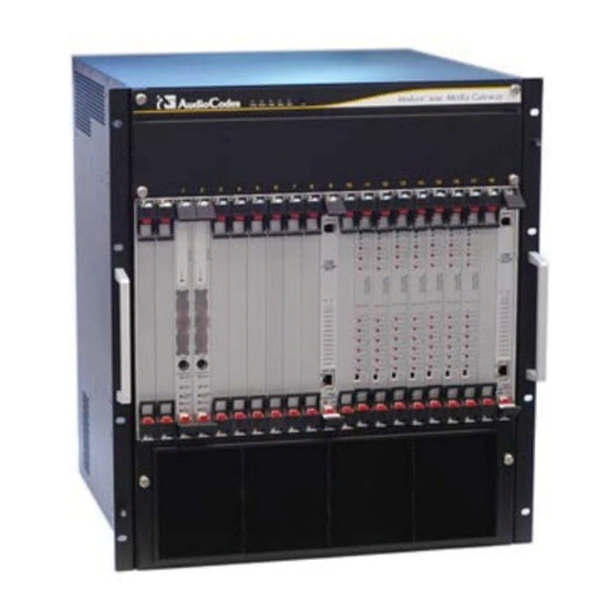
Sign In
Upload
Manuals
Brands
AudioCodes Manuals
Gateway
Mediant 8000
AudioCodes Mediant 8000 Manuals
Manuals and User Guides for AudioCodes Mediant 8000. We have
1
AudioCodes Mediant 8000 manual available for free PDF download: Installation, Operation & Maintenance Manual
AudioCodes Mediant 8000 Installation, Operation & Maintenance Manual (924 pages)
Brand:
AudioCodes
| Category:
Gateway
| Size: 12.62 MB
Table of Contents
Table of Contents
3
October
29
Related Documentation
30
1 Introduction
31
Figure 1-1: Mediant 8000 Block Diagram
31
Hardware Overview
33
2 Hardware Components
35
Table 2-1: Mediant 8000 Hardware Component
35
3 Front and Back Views
37
Figure 3-1: Mediant 8000 Front View
37
Figure 3-2: Mediant 8000 Back View
38
4 The Chassis
39
Figure 4-1: Midplane in Chassis
39
NEBS Compliancy
40
Midplane Keying
40
Table 4-1: Version Chassis Dimension
40
5 Power System
41
PEM/DC/8K Power Entry Module
41
Figure 5-1: PEM/DC/8K Power Entry Module Panel
41
PS/DC/8K Power Supply Module
42
DC Input Power
42
Figure 5-2: PS/DC/8K Power Supply Module
42
6 Cooling System
43
Air Flow
43
Figure 6-1: FM/8K Fan Tray Module
43
7 Alarm Indicators
45
Table 7-1: Alarm Indicator
45
8 TP-6310 Media Gateway Board
47
Figure 8-1: TP-6310 Board Front Panel
47
Table 8-1: TP-6310 Board Status LED Indicators
48
6310 /RTM - Rear Transition Module
49
Figure 9-1: 6310 RTM Front Panel
50
6310/RTM Redundant
51
Figure 9-2: 6310/RTM Redundant Front Panel
51
10 TP-8410 Media Gateway Board
53
Figure 10-1: TP-8410 Board Front Panel
53
Table 10-1: TP-8410 Board Leds
54
LED Array Display
55
8410 /RTM Rear Transition Module
57
Figure 11-1: 8410 RTM Panel
57
8410/RTM E1/T1 Trunk Connectors
58
Figure 11-2: 8410/RTM 100-Pin SCSI Connector
58
Table 11-1: 8410/RTM 100-Pin SCSI Connector
58
Figure 11-3: 8410/RTM 68-Pin SCSI Connector
59
Table 11-2: 8410/RTM 68-Pin SCSI Connector
60
8410/RTM Redundant
61
Figure 11-4: 8410/RTM Redundant Front Panel
61
12 System Controller (SC) Board
63
SC Rev.1 Board (Solaris OS)
64
Figure 12-1: SC Rev.1 Board Panel
64
Figure 12-2: SC Rev.1 Board Mini DIN 8 Serial Port Connector
65
SC Rev.1 Mini DIN 8 COM RS-232 Port
65
Status Leds
65
Table 12-1: SC Rev.1 Board LED Indicators
65
SC Rev.2 Board (Linux OS)
66
Figure 12-3: SC Rev.2 Board Panel
66
SC Rev.2 RS-232 Serial Port
67
Table 12-2: SC Rev.2 Board (Linux OS) RS-232 Connector Pinouts
67
USB Ports
67
VGA Port
67
Status Leds
68
Table 12-3: SC Rev.2 Board (Linux OS) LED Indicators
68
SA/RTM Synchronization and Alarm Rear Transition Module
69
Figure 12-4: SA/RTM Panel
69
SA/RTM RS-232 Console Port
70
Table 12-4: SA-RTM LED Indicators
70
Table 12-5: SA/RTM RS-232 Console Port Connector
70
Figure 12-5: RJ-48C Trunk Connectors
71
Table 12-6: SA/RTM Terminal Block Connector
71
Built-In LED Interface
72
Table 12-7: SA/RTM BITS Interface Leds
72
SA/RTM BITS (RJ48-C) Pin Signal Interface (Optional)
71
SA/RTM Terminal Block Connector
71
13 Ethernet Switch Board
73
ES/6600 es (Ethernet Switch) Board
73
Mediant
73
ES/6600 Board Panel
74
Figure 13-1: ES/6600 Board Panel
74
ES/6600 Leds
75
Table 13-1: ES/6600 Board Status Led Indicators
75
ES/6600 Physical Slots to Ethernet Port Mapping
76
Table 13-2: ES/6600 Physical Front Slots to Ethernet Port Mapping
76
ES/6600/RTM Rear Transition Module
78
Figure 13-2: ES/6600/RTM Panel
78
Table 13-3:ES/6600/RTM Port Pin Outs
79
ES (Ethernet Switch) Board
80
ES-2 Front Panel
81
Figure 13-3: ES-2 Board Panel
81
ES-2 Leds
82
Table 13-4: ES-2 Board Status Led Indicators
82
ES-2 Physical Slots to Ethernet Port Mapping
83
Table 13-5: ES-2 Physical Front Slots to Ethernet Port Mapping
83
Table 13-6: ES-2 Physical Rear Slots to Ethernet Port Mapping
84
ES-2 RTM Rear Transition Module
85
Figure 13-4: ES-2 RTM
85
Table 13-7: ES-2/RTM Port Pin Outs
86
Table 13-8: ES-2 RS-232 Pin Layout
86
14 Board Assembly Order
87
Table 14-1: Board Assembly Order
87
Getting Started
89
15 Site Preparation
91
Equipment Requirements
91
Table 15-1: Equipment Requirements
91
Cables
92
Table 15-2: Cabling Requirement
92
E1/T1 Cables for TP-8410
93
Table 15-3: Recommended E1/T1 Cable Parts for TP-8410 Board
93
Electrical Requirements
94
Table 15-4: Electrical Requirement
94
Environmental Requirements
95
Table 15-5: NEBS Requirement
95
Preparing the IP Network Connectivity
96
Allocating IP Addresses
97
Table 15-6: Allocating IP Addresses
97
Preparing the PSTN Network Connectivity
98
Preparing the STM-1/OC-3 PSTN Connections
98
Preparing the T3 PSTN Connections
98
Preparing the E1/T1 PSTN Connections
98
Installing the EMS Server and Client
98
16 Hardware Installation
99
Unpacking/Checking Contents
99
Mounting the Chassis on a Rack
100
Figure 16-1: Attaching the Chassis to the Rack
101
Earthing the Chassis
102
Figure 16-2: Chassis on the Rack - Front and Side Views
102
Lightning Protection
103
Powering up
103
Connecting the Mediant 8000 to the DC Power Supply
104
Figure 16-3: Connecting the Mediant 8000 to a DC Power Supply
104
Figure 16-4: Securing the PEM Plastic Cover Spacers (Hex)
105
Figure 16-5: Secure the PEM Plastic Cover Screws
106
Initial Power on
107
Table 16-1: PEM LED
107
17 The Command Line Interface (CLI)
109
Connecting to the CLI Via an RS-232 Serial Console
109
Figure 17-1: Using Putty for RS-232 Serial Connections
110
Table 17-1: RS-232 Serial Connection Properties
110
Figure 17-2: Putty RS-232 Serial Connection Settings
111
Connecting to the CLI Via the IP Internet Network
112
Connecting to the CLI Via Secure Shell (SSH)
112
Figure 17-3: Using Putty for SSH Connection
112
Command Line Interface Users
113
Table 17-2: Command Line Interface Users
114
Logging in as a Root User
115
Option 1
115
Option 2
115
Logging into the Command Line Interface
115
18 Connecting to the IP Network
117
Preparing the External Layer Switches or Routers
117
Configuring the Basic IP Network Parameters of SC Boards
118
Connecting IP Network Cables
121
Figure 18-1: Connecting the IP Network for an Initial Installation
121
19 Connecting to the PSTN Network
123
Connecting STM-1/OC-3 PSTN Cables
123
SFP Modules
123
Fiber Optic Cables
124
Figure 19-1: SFP Modules and Their Locks
124
Connecting the T3 PSTN Interfaces
125
Connecting E1/T1 PSTN Cables (TP-8410 Boards)
125
Figure 19-2: T3 - Male Connector MOLEX PN: 73100-0255
125
20 Connecting to External Telco Alarm Equipment
127
Figure 20-1: Normal Logic External Alarm Equipment Connection
127
Figure 20-2: Inverse Logic External Alarm Equipment Connection
128
21 Software Installation and Basic Configuration
129
Installing the Mediant 8000 Software
129
The Mediant 8000 Installation Package
130
Transferring the Mediant 8000 Installation Package to the SC Boards
131
Preparing for the Mediant 8000 Software Installation
133
Installing the Mediant 8000 Software on the SC Board to Operate as the Active Board
134
Installing the Mediant 8000 Software on the SC Board to Operate as the Standby Board
140
Peforming Basic Configuration of the Mediant 8000 Software
146
Performing Basic Configuration of the Mediant 8000 Software on the SC Board to Operate as the Active Board
147
Performing Basic Configuration of the Mediant 8000 Software on the SC Board to Operate as the Standby Board
150
Starting Mediant 8000 Software
153
Configuring Connectivity with the EMS Server
154
22 Advanced Configuration
155
Configuring and Operating the Media Gateway (Part 1)
157
23 Overview
159
Management Interfaces
159
Audiocodes Element Management System (EMS)
159
SNMP Management Interface
160
CLI Management Interface
160
Syslog Management Interface
160
Managed Objects, Administrative and Operational State
160
MO Tree Hierarchy
161
MO States
161
Figure 23-1: Sample MO Tree Hierarchy
161
Lock/Unlock Actions
162
Managed Objects (Mos) in the EMS
162
Figure 23-2: Graphical EMS Status Screen
163
Figure 23-3: Textual EMS Status Screen
163
Figure 23-4: Navigation Pane and Info Panel in EMS
164
Modifying the Media Gateway Configuration
165
Table 23-1: MO Attribute Provisioning Types
165
Figure 23-5: EMS Configuration Pane
166
Figure 23-6: Example Settings Screen-Trunk Settings
166
Faults and Alarms Monitoring
167
Figure 23-7: EMS Alarm Browser
167
Table 23-2: EMS-Alarm Severity Color
168
Mediant
168
Figure 23-8: Mos in the EMS Color-Ccoded According to Their Severity
169
Alarm Throttling
170
Table 23-3: MO Severity Colors in the EMS
170
24 SNMP Management Interface
171
Configuring Connectivity between the Media Gateway and the EMS Server171
171
Mediant
171
Configuring Connectivity between the Media Gateway and Additional SNMP Managers
175
25 Syslog Management Interface
177
Table 25-1: SNMP to Syslog Severity Mapping
177
Configuring Connectivity between the Media Gateway and the Syslog Server178
178
Securing the Syslog Management Interface
178
26 Connecting the Media Gateway to the IP Network
179
Establishing Connectivity with the EMS Server
180
Configuring Network Topology
183
Types of IP Network Traffic and Network Subnets
183
Figure 26-1: Network Subnets
184
Use of OAM, Control and Media Subnets by Mediant 8000 Boards
185
Connecting Mediant 8000 to IP Network
185
Configuring IP Network Interfaces
186
Figure 26-2: an Example of "Two O & CM" Subnet Configuration
187
Working with Vlans
188
Configuring VLAN Tags
188
Using Tagged Vlans for Subnet Separation
188
Configuring VLAN Tags for Media and Control Subnets
189
Configuring VLAN Tags for OAM Subnet
189
Media Link Aggregation
191
Benefits
191
Distribution Rules
191
Aggregated Link Failure Detection
193
Link Aggregation Control Protocol
193
Table 26-1: Aggregated Link Failure Detection
193
Configuring Media Link Aggregation
194
Table 26-2: Media Link Aggregation Settings
194
Configuring IP Network Connectivity on SC Boards
196
Additional OAM Subnet Configuration
197
Configuring IP Network Connectivity on Media Gateway Boards
198
IP Subnets
198
Configuring IP Subnets
199
Table 26-3: Subnet Properties
199
IP Network Profiles
200
Attaching IP Network Profile to the Media Gateway Board
201
Creating IP Network Profile
201
Configuring Media Gateway Board's IP Addresses
202
Additional Network Settings
203
Static Routes
203
Static Routes for SC Boards
203
Static Routes for Media Gateway (TP) Boards
204
Table 26-4: SC Static Route Properties
204
Table 26-5: TP Static Route Properties
205
Quality of Service
206
Table 26-6: Network Service Classes
206
Ethernet Frame Priority Header
207
Differentiated Services (Diffserv)
208
Table 26-7: Media Gateway Quality of Service Settings
208
Table 26-8: Network Profile Quality of Service Settings
209
Configuring Ipv6
210
Configuring Media Realms
210
Table 26-9: Media Realm Settings
211
Additional Network Services and Settings
212
Table 26-10: Additional Media Gateway Board Network Settings
212
Activating New Network Interfaces Configuration
214
Offline Network Configuration of ES/6600
214
Offline Network Configuration of ES-2
215
Online Network Configuration
215
Activating Offline Network Configuration
216
Connecting the Mediant 8000 to the IP Network
217
Ethernet Ports Allocation on the ES/6600 Board
217
Table 26-11: Ethernet Ports Allocation on ES/6600 Boards
217
Ethernet Ports Allocation on ES-2-SINGLE Boards
219
Table 26-12: Ethernet Ports Allocation on ES-2 Boards
219
External Layer 3 Ethernet Switches or Routers
221
Figure 26-3: Ethernet Port Allocation
221
Configuring HSRP/VRRP Protocols on External Layer 3 Switches
222
Configuring the Mediant 8000 for the HSRP Protocol
222
27 Working with the SC Boards
223
Redundancy Mode
223
SC Boards in the EMS
224
Figure 27-1: SC Boards in EMS
224
SC Board Actions
225
SC Board Hardware Revisions
225
The Operating System on the SC Boards
226
Installing the Solaris os on the SC Rev.1 Board
227
Verifying the Current Version of the Solaris os on the SC Board
227
Installation Requirements
228
Preparing the 'Install Image' on the Install Server (EMS)
228
Installing the Solaris 9 os on the SC Board
229
Installing the Linux os on the SC Rev.2 Board
231
Verifying the Current Version of the Linux os on the SC Board
231
Linux os Installation Requirements
232
Table 27-1: Linux os Installation Requirements
232
Re-Installing the Linux os Via the Remote Network Connection
233
Re-Installing the Linux os Via the RS-232 Serial Console
235
Console
238
Installing the Linux os from the USB Flash Drive Via the RS-232 Serial Console
238
Preparing the USB Flash Drive
238
Figure 27-2: Format New Volume
239
Figure 27-3: ISO2USB
240
Installing from the USB Flash Drive
241
Installing the Linux os from the USB CD/DVD Drive Via the
244
RS-232 Serial Console
244
28 Working with the Media Gateway Boards (TP-6310 and TP-8410)
245
Redundancy Model Overview
245
Media Gateway Boards in the EMS
246
Figure 28-1: Media Gateway Boards in the EMS
246
Hardware and Application Types
247
Media Gateway Board Actions
247
The Redundancy Model
249
Configuring Redundant Media Gateway Board
249
Redundancy Modes
250
Desired Redundancy Mode
251
Actual Redundancy Mode
252
Figure 28-2: Board Redundancy Status
253
Activity Switchover
254
Multiple Redundancy Groups
255
Table 28-1: Redundancy Group Parameters
256
Table 28-2: Media Gateway Board Redundancy Parameters
257
Automatic Switchback
258
Table 28-3: Automatic Switchback Parameters
258
Updating License Key
259
Mediant
259
29 Working with the es Boards
261
ES Redundancy Mode
261
ES Boards in the EMS
261
Figure 29-1: es Boards in the EMS
261
ES Board Actions - ES/6600
262
ES Board Actions - ES-2
262
Configuring and Operating the Media Gateway (Part 2)
263
30 Time and Date Configuration
265
Time Zone Settings
265
Using the EMS Server as the NTP Server
266
Using External NTP Servers
266
Figure 30-1: EMS Server Configured as NTP Server
266
External NTP Servers Setup - Option 1
267
Figure 30-2: External NTP Server Setup - Option 1
267
External NTP Servers Setup - Option 2
268
Figure 30-3: External NTP Server Configuration - Setup Option 2
268
NTP Synchronization and Status
269
Internal NTP Implementation
270
Figure 30-4: Internal NTP Implementation
270
Configuring NTP Servers
271
Table 30-1: NTP Server Configuration Parameters
271
Viewing NTP Servers' Status
273
Table 30-2: NTP Server Status Parameters
273
31 Configuring the MGCP/MEGACO Protocols
277
Media Gateway Controller
277
Media Gateway Controller in the EMS
277
MGCP Control Protocol
278
MEGACO Control Protocol
278
Media Gateway Controller Addressing
279
Via FQDN Name
279
Via IP Addresses
279
Endpoint Name Provisioning
280
Physical Terminations
280
Table 31-1: Physical Termination Types
280
Ephemeral Terminations (for MEGACO Only)
281
Example 1
281
Example 2
281
Example 3
281
Domain Name Provisioning
282
MEGACO Virtual Gateways
282
Configuring MGCP/MEGACO Call Control Settings
283
Configuring MEGACO Virtual Gateways
283
Table 31-2: Virtual Gateway Parameters
283
Configuring Media Gateway Controller
285
Table 31-3: Media Gateway Controller Parameters
285
Table 31-4: Media Gateway Controller Addressing Parameters
286
Table 31-5: Media Gateway Controller Endpoint Names Parameters
286
Table 31-6: MGC IP/FQDN Address Parameters
287
Associating Media Gateway Controller with Media Gateway Boards
288
Configuring Additional MGCP/MEGACO Settings
289
Table 31-7: Media Gateway Board's Call Control Parameters
289
32 V5.2 Access Gateway
293
Overview
293
Working with the V5.2 Access Gateway
294
V5.2 Interface Status and Maintenance Actions
294
V5.2 Link Status and Maintenance Actions
295
V5.2 User Ports Status
295
Configuring the V5.2 Access Gateway
296
Configuring Media Gateway Board's PSTN Parameters
296
Configuring Trunks for the V5.2 Access Gateway Application
296
Configuring V5.2 Interfaces
297
Table 32-1: V5.2 Interface Properties
297
Configuring V5.2 Links
298
Table 32-2: V5.2 Link Properties
298
Configuring V5.2 User Ports
299
Bringing V5.2 Interfaces "In Service
301
33 Configuring Security Settings
303
Figure 33-1: Security Features
304
Security Configuration Guidelines
305
Secure Operation Mode
306
Enabling Secure Operation Mode
307
Disabling Secure Operation Mode
308
Secure Access to the SNMP Management Interface
308
Secure Access to the CLI Interface
309
SCP and SFTP Protocols
309
SSH Protocol
309
Disabled Remote Root Login
309
Enabling a Direct Remote Root Login
310
Disabling a Direct Remote Root Login
311
OS Hardening
311
OS Security Patches (on SC Boards)
312
Installing os Security Patches from a Latest Installation Package
313
Installing the Latest os Security Patches from the "OS Security Patch Bundle
315
File System Integrity
316
Viewing the File System Integrity Status
316
Table 33-1: Filesystem Integrity Status Parameters
317
Scheduling File System Integrity Check
318
Restoring File System Integrity
319
Table 33-2: Filesystem Integrity Configuration Parameters of the Media Gateway
319
OS Auditing on SC Boards
320
Auditing Goal
320
Auditing Trail File
320
Analyzing the Audit Trail File on the Linux os
321
Analyzing the Audit Trail File on the Solaris os
321
OS Auditing on the Mediant 8000 Media Gateway
321
Public Key Infrastructure
325
Initial Configuration
326
Self-Signed Certificate
327
Figure 33-2: Generating X.509 Files
328
Generating a Certificate Signing Request (CSR)
329
Activating the New X.509 Certificates on the Media Gateway
331
Adding Certificates to the Auxiliary Files Repository
331
Table 33-3: Media Gateway Security Settings
332
Table 33-4: X.509 Files Status Parameters of the Media Gateway
333
Figure 33-3: Activating X.509 Certificates
335
Configuring an X.509 Certificate Expiration Date Reminder
336
Generating a New Private Key
337
Checking Certificate Revocation Status
338
Table 33-5: OCSP Server Settings
338
IPSEC and IKE
339
Figure 33-4: Ipsec Encryption
339
For Management Interfaces (on SC Boards)
339
IKE Protocol
339
For Call Control and Signaling Interfaces (on TP Boards)
340
IKE Protocol
340
IPSEC Protocol
340
Configuring IPSEC/IKE for Management Interfaces (on SC Boards)
341
Mediant
341
Table 33-6: SNMP Management Modes
341
Table 33-7: SC IPSEC Rule Parameters (SC Boards)
342
Table 33-8: SC IKE Proposal Parameters
345
Configuring IPSEC/IKE for Call Control and Signaling Interfaces (on TP Boards)
346
Table 33-9: TP IPSEC Profile Parameters
346
Table 33-10: TP IPSEC Rules Parameters (TP Boards)
347
Table 33-11: TP IKE Proposal Parameters
348
SIP over SSL/TLS (SIPS)
349
Media Security
350
Packet Cable Security
350
Secure RTP
350
Table 33-12: Media Gateway Board's Media Security (SRTP) Settings
351
Firewall Functionality on Media Gateway Boards
353
Firewall Rules
353
Table 33-13: Firewall Rule Parameters
354
Network Services on the Mediant 8000
357
Table 33-14: Network Services
357
Openboot PROM on SC Rev.1 Boards
358
CLI Login Banner
360
Administering Command Line Interface (CLI) Users
361
CLI Users Database and Operation Modes
361
Administering the ROOT User
362
Changing the ROOT User Password
362
Recovering the ROOT User Password
364
Administering the EMS User
365
Changing the Password of the EMS User
365
Figure 33-5: Synchronizing CLI Users Database with EMS Server
367
Synchronization Modes
367
Synchronizing the CLI Users Database with the EMS Server
367
CLI User Synchronization with the EMS Server
368
Administering the Local CLI User Database
369
Figure 33-6: Local CLI Users Database on SC Boards
369
Creating a New CLI User
370
Deleting a CLI User
372
Changing Password of the CLI User
373
Centralized AAA Servers
375
Centralized TACACS+ Servers
375
Figure 33-7: Working with Centralized TACACS+ Servers
377
Table 33-15: Centralized AAA Server Settings
380
Table 33-16: AAA Server Settings
380
Table 33-17: TACACS+ Settings
381
Centralized RADIUS Servers
384
Figure 33-8: Centralized User Authentication Via RADIUS Protocol
385
Table 33-18: RADIUS Settings
387
CLI Interface Access Control
389
Table 33-19: CLI Interface Access Control Parameters
389
Generating a Private/Public Key Pair
390
Password-Less Access to the CLI Interface
390
Figure 33-9: Putty Key Generator
391
Figure 33-10: Putty Key Generator-Public Key
392
Figure 33-11: Putty Key Generator-Generate Action
392
Figure 33-12: Putty Client-SSH Authentication
394
Figure 33-13: Putty Configuration-Auto-Login
395
Figure 33-14: Putty Configuration-Host Name
396
Intrusion Detection Events
398
Configuration Freeze and Configuration Change Event
399
34 Performance Measurements
401
PM Profiles
401
Real-Time Pms
401
Historic Pms
401
PM Threshold Alarms
401
Performance Monitoring Profiles
402
Figure 34-1: MG Background Monitoring
402
Figure 34-2: Do You Wish to Start Polling
403
Figure 34-3: Polling Started
403
Real-Time Performance Measurements
405
Figure 34-4: Select Screen
405
Figure 34-5: Real-Time Performance Measurement Display Window
406
Figure 34-6: MG Monitoring Window
407
History Performance Measurements
409
Figure 34-7: History Pms Select Screen
409
Figure 34-8: History Performance Measurements Display
410
Figure 34-9: History Performance Measurements Display-Results Screen
411
Performance Measurement Threshold Alarms
412
Figure 34-10: Threshold Alarms Parameters Screen
413
Table 34-1: PM Threshold Alarm Settings
413
35 Media Gateway Inventory
415
Figure 35-1: Mediant 8000 Inventory
415
36 Media Gateway Boards' Configuration Backdoor
417
Table 36-1: Configuration-Backdoor Parameters
418
Supported Actions
420
Usage Tips
420
37 Using Auxiliary Files
421
Table 37-1: Supported Auxiliary Files
421
Auxiliary Files Repository
422
Call Progress Tones (CPT) Files
422
Modifying the "Source" Call Progress Tones (CPT) File
423
The Call Progress Tones Section Format
423
The User-Defined Tones Section Format
425
Default Configuration
426
Table 37-2: Default Call Progress Tones
426
Editing the "Source" Call Progress Tones File
428
Converting the Call Progress Tones File to Binary Format
429
Figure 37-1: Call Progress Tones Screen
429
Pre-Recorded Tones (PRT) Files
430
Table 37-3: Pre-Recorded Tones (PRT) File Characteristics
430
Creating a Pre-Recorder Tones File
431
Figure 37-2: Prerecorded Tones File(S) Screen with Wav Files
432
Figure 37-3: File Data Dialog Box
432
Voice Prompts Files
433
Creating a Voice Prompts File
433
Figure 37-4: Voice Prompts Screen
433
Figure 37-5: Select Files Window
434
Figure 37-6: Voice Prompts Window with Wav Files
435
Figure 37-7: File Data Window
436
CAS Files
437
CAS File Syntax
437
Actions
438
Functions
438
INIT Variables
438
States
438
Table 37-4: Example - ST_DIAL State in cas File
438
Reserved Words
440
State's Line Structure
440
Next State
445
Converting cas File to Binary Format
451
Figure 37-8: Call Associated Signaling (CAS) Screen
452
External Coders Files
453
Modifying the "Source" External Coders File
453
Coders Support Level
454
New Coders Introduced with the Table
454
Converting External Coders File to Binary Format
455
Dial Plan Prefix Tags for IP-To-Tel Routing
456
Mediant
456
38 Configuring the PSTN Subsystem
459
Configuring Media Gateway Board's PSTN Settings
459
Table 38-1: Media Gateway Board's PSTN Parameters
459
Configuring STM-1/OC-3 Interfaces
460
Figure 38-1: TP-6310 Board Status Screen
461
Table 38-2: PSTN Fiber Group Properties
462
Configuring T3 Interfaces
463
Channelized T3
464
Configuring the E1/T1 Trunks
465
Status in the EMS
465
Supported Actions
466
Trunks Configuration
467
Table 38-4: Trunk Properties
468
Viewing Trunk Channels Status
470
Table 38-5: Trunk PSTN Alarm
471
Configuring the SS7 Subsystem
472
SIGTRAN (or UAL)
473
Supported SS7 Architectures
473
SS7 M2UA (SG Side) Architecture
474
SS7 MTP3/M3UA Architecture
474
SS7 M2TN Tunneling Architecture
475
Configuring the M2UA (SG Side) Application
476
Table 38-7: SS7 Data Link Properties - Data Link General Info Tab
478
Table 38-8: SS7 Data Link Properties - Data Link MTP Tab
479
Table 38-9: UAL Group Properties
480
Table 38-10: UAL Interface Properties
481
M2UA (SG Side) Operational Status
482
Online Provisioning
482
Redundant Configuration
482
Advanced Configuration
483
Configuring the MTP3/M3UA Application
485
Table 38-12: MTP3 Group Properties
490
Table 38-13: SS7 Node Properties
491
Table 38-14: SS7 Linkset Properties
493
Table 38-15: SS7 Routeset Properties
494
Table 38-17: SS7 Route Properties
495
Table 38-20: Media Gateway Board's MTP3/M3UA Properties
497
MTP3/M3UA Operational Status
498
Online Provisioning
498
Redundant Configuration
499
Advanced Configuration
503
STP Functionality (Alias Point Code)
503
Configuring the M2TN Application
504
Advanced Configuration
506
Online Provisioning
506
Redundant Configuration
506
Configuring the CAS/ISDN Subsystem
507
Configuring the CAS/ISDN Application
508
Table 38-23: E1/T1 Trunk's ISDN/DPNSS Parameters
509
Table 38-24: E1/T1 Trunk's cas Parameters
512
Configuring the IUA/DUA Application
513
Online Provisioning
515
ISDN Operational Status
515
Redundant Configuration
515
Configuring TDM Clock Synchronization
516
Stand Alone Board Clock Mode
516
Configuring the Media Gateway Software
517
Connecting the Media Gateway to the External Equipment
517
Timing Module BITS Sync Clock Mode
519
Configuring Media Gateway Software
520
Connecting Media Gateway to the External Equipment
520
Table 38-26: TM External if Settings Parameters
521
Timing Module Line Sync Clock Mode
522
Connecting the Media Gateway to the External Equipment
523
Configuring Media Gateway Software
524
39 Configuring the Media Settings
527
Table 39-2:Media Gateway Board's RTP/RTCP Settings
532
Table 39-3: Media Gateway Board's Fax/Modem Settings
534
Table 39-4:Media Gateway Board's Caller ID Settings
535
Table 39-5:Media Gateway Board's Coder Settings
537
Table 39-7:Media Gateway Board's no Op Settings
538
DSP Templates
539
AMR Coder Policy
540
Configuring Pre-Defined AMR Coder Rate Policy
541
Table 39-10: AMR Coder Profile Settings
542
Configuring and Operating the Media Gateway (Part 3)-SIP Subsystem
545
40 General SIP Configuration
547
The SIP Proxy
547
SIP Proxy Set
547
Redundancy Mechanisms
548
DNS Service Records (SRV)
548
SIP Proxy Sets
548
Table 40-1: SIP Proxy Set Parameters
549
Table 40-2: SIP Proxy Set Settings
553
The SIP Registrar
558
SIP Protocol Settings
563
Table 40-6: SIP Protocol Settings
566
Table 40-7: SIP Routing Settings
578
Table 40-8: SIP Supplementary Services Settings
582
Table 40-9: SIP PSTN Settings
587
Table 40-10: SIP Media Settings
601
Mediant
602
Table 40-11:SIP Media Server Settings
604
Table 40-12:SIP Radius Settings
606
Configuring Coder Groups
608
Configuring Coders Table
609
Table 40-14: Coder Parameters
610
IP Groups Table
611
Configuring the IP Group Table
611
Table 40-15: IP Group Parameters
612
Account Group
622
Configuring Account Group
622
SIP Routing DNS Table
625
Configuring the Internal DNS Table
625
SIP SRV to IP Table
626
Configuring the SIP SRV to IP Table
626
Table 40-18: SIP SRV to IP Table Parameters
627
SRD Table
628
Configuring the SRD Table
629
SIP Interfaces Table
630
Configuring the SIP Interfaces Table
630
NAT Translation Table
632
Configuring the NAT Translation Table
632
Least Cost Routing (LCR) Table
633
Configuring the Routing Rule Groups Table
634
Configuring the Cost Group Table
635
Configuring the Time Band Table
636
SIP Message Policy Table
637
Configuring the SIP Message Policy Table
637
Table 40-22: SIP Message Policy Parameter
638
Routing Based on LDAP Active Directory Queries
639
Configuring LDAP Server Parameters
640
Querying the AD and Routing Priority
642
Configuring Query Attribute Key
644
Configuring AD-Based Routing Rules
645
Mediant
646
Table 40-28: AD-Based Tel-To-IP Routing Rule Configuration Examples
647
41 PSTN Gateway and IP-To-IP Applications
649
Trunk Groups Table
650
Table 41-2: Trunk Group Parameters
651
Trunk Group Settings Table
653
Manipulation Tables
658
Table 41-4: GW Inbound/Outbound Manipulation Set ID Parameter
659
Table 41-5: Calling Name Manipulation Table for IP to Tel Table Parameter
660
Configuring the Calling Name Manipulation Table for Tel to IP Routing
661
Configuring the Redirect Number Manipulation IP to Tel Routing
662
Configuring the Redirect Number Manipulation Tel to IP Routing
663
Table 41-8: Redirect Number Manipulation Tel to IP Table Parameter
664
Operation Rules
665
Dialing Plan Notation
666
The Routing Tables
668
Telephone to Ip/Outbound Routing Table
669
Configuring Telephone to Ip/Outbound Routing
671
Table 41-11: Telephone to IP / Outbound Routing Table "Matching Rules
672
Table 41-12: Telephone to IP / Outbound Routing Table "Destination Rules
673
IP to Telephone/Inbound Routing Table
675
Configuring IP to Telephone/Inbound Routing
676
Table 41-13: IP to Telephone / Inbound Routing Table "Matching Rules
677
Reasons for Alternative Routing
679
Table 41-15: Alternative Routing Parameters
680
SIP to ISDN and ISDN to Release Cause Mapping
681
Table 41-16: SIP to ISDN Cause Mapping Parameters
682
Profiles Tables
683
Tel Profile Table
684
IP Profile Table
689
Table 41-19: IP Profiles Parameters
690
42 Stand-Alone Survivability (SAS) Application
715
The SAS Configuration
716
SAS Registration Manipulation
723
43 Session Border Controller (SBC) Application
725
Topology Hiding
726
The SBC Configuration
727
SIP Network Definitions
737
SIP Interfaces
738
SIP Dialog Initiation Process
739
Determining Source and Destination URL
740
Figure 43-4: SBC Application Classification Process
741
Table 43-2: SBC Classification Parameters "Matching Rules
742
Table 43-3: SBC Classification Parameters "Operation Rules
743
SBC Condition Table
744
SBC Routing
745
Figure 43-5: SBC Application IP to IP Routing Types
746
Configuring the SBC IP to IP Routing Table
747
Table 43-6: SBC IP to IP Routing Table "Destination Rules
749
Configuring SBC Alternative Route Reasons Table
753
SBC Inbound and Outbound Manipulation
754
SBC IP to IP Inbound Manipulation Table
755
Table 43-9: SBC IP to IP Inbound Manipulation Table "Matching Rules
756
Table 43-10: SBC IP to IP Inbound Manipulation Table "Operation Rules
757
SBC IP to IP Outbound Manipulation Table
758
Table 43-12: SBC IP to IP Outbound Manipulation Table "Operation Rules
760
SBC Message Manipulation
761
Figure 43-8: SBC Message Manipulation
762
Configuring the SBC Message Manipulation Table
763
User Registration
765
Registrations Database
766
Routing Using Registrations Database
767
SBC Admission Control
768
SBC Media Handling
770
Media Anchoring Without Transcoding (Transparent)
771
Media Anchoring with Transcoding
772
Transcoding Modes
774
Maintenance
775
44 Media Gateway Software Backup/Restore Procedures
777
Creating the Media Gateway Software Backup
778
Figure 44-2: Backup Files in the EMS
779
Restoring the Media Gateway Software from Backup
783
Figure 44-4: Select Backup File
784
Automatic Backups
788
45 Hardware Replacement
791
Emtpy Slots Cover Requirements
792
SC Board Replacement Procedure
793
Installing the Operating System (OS) on the Replaced SC Board
794
Installing the Software on the Replaced SC Board
795
Replacing the Media Gateway Board's RTM Module
796
Connecting Cables to Media Gateway's RTM Module
797
Mediant
798
Troubleshooting the Newly Installed Media Gateway Board
799
SA/RTM Replacement Procedure
800
Ethernet Switch Board Replacement Procedure
801
Replacing the Ethernet Switch RTM Module
802
Troubleshooting the ES/6600 Board Installation
803
Power Supply Modules Replacement
804
Figure 45-5: Removing the PS from the Chassis
805
Replacing the Power Entry Module
806
Replacing the Fan Tray Modules
807
Replacing Air Filters
808
46 Online Software Upgrade
811
Hitless Upgrade Mode
812
Pre-Upgrade Configuration Backup
813
Preparing the IP Network
814
Pre-Installing os Patches
817
Configuring the EMS and ROOT Passwords of the Mediant 8000 in the EMS
818
Adding the Media Gateway Software to the EMS Server
819
Performing the Online Software Upgrade
820
Welcome Questionnaire
821
Transferring the SC Software Package to the SC Boards
823
Upgrading the Media Gateway Boards
826
After Completing the Online Software Upgrade
827
Rollback
828
Performing a Manual Rollback to the Previous Software Configuration
829
Recovery from a Network Failure or EMS Server/Client Crash
831
Diagnostics and Troubleshooting
833
47 Troubleshooting Strategy
835
48 Recovering the OAM VLAN Settings
843
49 Collecting Advanced Media Gateway Board Logs
845
Displaying Voip Board Log Files
846
Filtering Syslog Messages and Debug Recordings
848
Table 49-1: SIP Logging Filter Properties
849
Media Gateway Board's Debug Recording Traces and Logging
850
Collecting Debug Recording Traces on the Standby SC Board
851
Collecting Call Data Records (Cdrs)
852
Table 49-2: CDR Report Level
853
Collecting Call Data Records (Cdrs) on MEGACO Boards
854
Collecting the Media Gateway Board's INI File
855
50 Accessing Advanced Status- Media Gateway Board Via WEB
857
51 Collecting Traces from the Ethernet Switch Board's Mirror Port
859
Figure 51-1: IP Packets
860
Mediant
861
Table 51-1: ES/6600 and ES-2 Mirror Filter Properties
862
Table 51-2: Additional ES/6600 Mirror Filter Properties
864
Configuring Mirroring on es Boards' Port
867
Configuring Mirror Destination
868
Starting Mirroring on es Board
869
52 Internal System Controller (SC) Software Logs
871
Log Files Storage
872
Viewing Log Files
873
Operating System Logs
874
53 Information Needed When Contacting Technical Support
877
Appendices
879
A Examples of IP Network Connectivity Configuration
881
A.2 Example 2: Three Subnets, VLAN Tags, One Physical Interface
885
B Appendix - Configuring HSRP/VRRP
889
Figure B-1: HSRP/VRRP Configuration
890
B.2 Configuring the Mediant 8000 Subnets
891
Mediant
892
B.2.8 Gateway Parameters Provisioning
893
B.3.3 Cisco L3 Switch-HSRP
894
B.3.4 Example Configuration Output
895
B.3.5 "Show Running-Config" of 3560_G3
899
Figure B-2: HSRP/VRPP Test State 1
900
Figure B-3: HSRP/VRPP Test State 2
901
Figure B-4: HSRP/VRPP Test State 3
902
Figure B-5: HSRP/VRPP Test State 4
903
C Appendix: Testing Installation and Basic Configuration
905
D Appendix - List of Notification Traps
911
54 Index
913
Advertisement
Advertisement
Related Products
AudioCodes Mediant 800
AudioCodes Mediant 800B
AudioCodes Mediant 800 MSBG
AudioCodes Mediant 800C
AudioCodes Mediant 800C SBC
AudioCodes Mediant 600
AudioCodes Mediant 1000
AudioCodes Mediant 2000
AudioCodes Mediant 1000B
AudioCodes Mediant TP-1610 H.323
AudioCodes Categories
Gateway
IP Phone
Network Router
Controller
Adapter
More AudioCodes Manuals
Login
Sign In
OR
Sign in with Facebook
Sign in with Google
Upload manual
Upload from disk
Upload from URL