AudioCodes Mediant 800 MSBG Installation Manual
Multi-service business gateway, sip protocol
Hide thumbs
Also See for Mediant 800 MSBG:
- User manual (890 pages) ,
- Cli reference manual (160 pages) ,
- Release notes (178 pages)

Related Manuals for AudioCodes Mediant 800 MSBG


Summary of Contents for AudioCodes Mediant 800 MSBG
- Page 1 Mediant™ 800 MSBG Multi‐Service Business Gateway SIP Protocol Installation Manual Version 6.2 February 2011 Document # LTRT‐10205 ...
-
Page 3: Table Of Contents
Installation Manual Contents Table of Contents Introduction ......................9 Installing the Device ..................11 2.1 Physical Description ....................11 2.1.1 Physical Dimensions ....................11 2.1.2 Front Panel ......................11 2.1.3 Rear Panel ......................13 ... - Page 4 Mediant 800 MSBG 3.8.2 Loading ini and Auxiliary Files ................60 Monitoring the Device ..................61 4.1 Front-Panel LEDs ....................61 4.2 Web Interface ......................62 4.2.1 Viewing Alarms ....................... 62 4.2.2 Viewing Channel Status ..................63 ...
- Page 5 Installation Manual Contents List of Figures Figure 1-1: Summary of Installation Steps....................9 Figure 2-1: Front Panel .......................... 11 Figure 2-2: Rear Panel .......................... 13 Figure 2-3: Rubber Foot Attached to Underside of Device..............15 Figure 2-4: Peeled-off Rubber Foot ....................... 15 ...
- Page 6 Mediant 800 MSBG Figure 3-32: Configuration File Page ..................... 55 Figure 3-33: Start Software Upgrade Wizard Screen ................58 Figure 3-34: End Process Wizard Page ....................59 Figure 3-35: Load Auxiliary Files Page ....................60 Figure 4-1: Current Alarms in Active Alarms Page ................62 ...
- Page 7 This document is subject to change without notice. Date Published: February-07-2011 Trademarks AudioCodes, AC, AudioCoded, Ardito, CTI2, CTI², CTI Squared, HD VoIP, HD VoIP Sounds Better, InTouch, IPmedia, Mediant, MediaPack, NetCoder, Netrake, Nuera, Open Solutions Network, OSN, Stretto, TrunkPack, VMAS, VoicePacketizer, VoIPerfect, VoIPerfectHD, What’s Inside Matters, Your Gateway To VoIP and 3GX are trademarks or...
- Page 8 Mediant 800 MSBG Related Documentation Document Name SIP Release Notes Mediant 800 MSBG SIP User's Manual MSBG Series CLI Reference Guide Product Reference Manual Note: Throughout this manual, unless otherwise specified, the term device refers to Mediant 800 MSBG. Note: Open source software may have been added and/or amended for this product.
-
Page 9: Introduction
Installation Manual 1. Introduction Introduction This manual provides you with step-by-step procedures for initial and basic setup of the device, including hardware installation and software configuration. The flowchart below summarizes these steps. Figure 1-1: Summary of Installation Steps Note: For detailed information on how to fully configure the device, refer to the device's User’s Manual. - Page 10 Mediant 800 MSBG Reader’s Notes Installation Manual Document #: LTRT-10205...
-
Page 11: Installing The Device
Installation Manual 2. Installing the Device Installing the Device This section describes the device's hardware installation, which includes the following: Physical description of the device (refer to 'Physical Description' on page 11) Unpacking the shipped carton and verifying contents (refer to 'Unpacking the Package Contents' on page 13) Mounting the device (refer to 'Mounting the Device' on page 15) Cabling the device (refer to 'Cabling the Device' on page 17) -
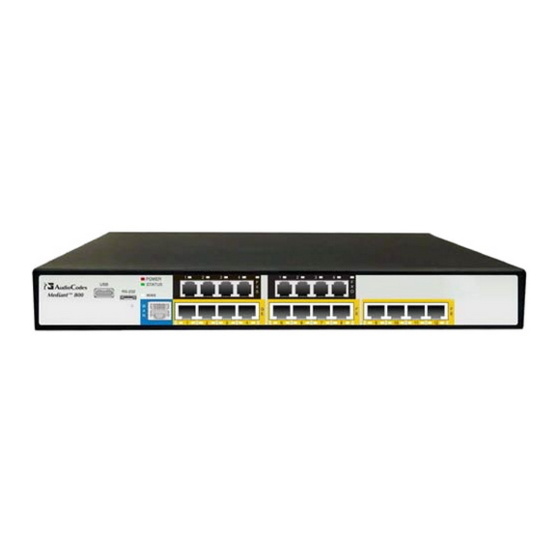
Page 12: Table 2-2: Front-Panel Description
Mediant 800 MSBG Table 2-2: Front-Panel Description Item Description Label POWER / LEDs indicating the status of the power, reboot/initialization, and WAN STATUS / interface. FXS / FXO / These I/O interfaces can include the following interface groups, depending BRI / Digital on the ordered model: FXS interfaces, providing four RJ-11 ports per group. -
Page 13: Rear Panel
Installation Manual 2. Installing the Device 2.1.3 Rear Panel The device's rear panel is shown in the figure below and described in the subsequent table. Figure 2-2: Rear Panel Note: The figure above is used only as an example. The OSN server ports are available only if ordered. -
Page 14: Unpacking The Package Contents
One FXS Lifeline cable adapter (only for models with FXS interfaces) • T1 WAN splitter cable (only for models with T1 WAN interface) • One AC power cable Check, retain and process any documents. Notify AudioCodes or your local supplier of any damage or discrepancies. Installation Manual Document #: LTRT-10205... -
Page 15: Mounting The Device
Installation Manual 2. Installing the Device Mounting the Device The device can be mounted in one of the following ways: Placed on a desktop (refer to 'Desktop Mounting' on page 15) Installed in a standard 19-inch rack (refer to '19-Inch Rack Mounting' on page 16) Warning: Do not place any equipment directly on top of the device or adjacent to its sides (at least 13-cm separation). -
Page 16: 19-Inch Rack Mounting
Mediant 800 MSBG 2.3.2 19-Inch Rack Mounting The device can be installed in a standard 19-inch rack by implementing one of the following mounting methods: Placing it on a pre-installed shelf in a 19-inch rack (refer to 'Using a Pre-installed Rack Shelf' on page 16). -
Page 17: Using Mounting Brackets
Installation Manual 2. Installing the Device 2.3.2.2 Using Mounting Brackets The procedure below describes how to mount the device in a 19-inch rack. Rack mounting involves placing the device on a pre-installed rack shelf and then attaching the device's mounting brackets (to the device and rack frame). The purpose of the mounting brackets is to secure the device to the rack. -
Page 18: Cabling The Device
Mediant 800 MSBG Cabling the Device This section describes the cabling of the device, which includes the following: Connecting to earth/ground (refer to ‘Grounding the Device’ on page 19) Protective Earthing The equipment is classified as Class I EN60950 and UL60950 and must be earthed at all times. -
Page 19: Grounding The Device
Installation Manual 2. Installing the Device 2.4.1 Grounding the Device The device must be connected to earth (grounded) using an equipment-earthing conductor. Protective Earthing The equipment is classified as Class I EN60950 and UL60950 and must be earthed at all times. For Finland: "Laite on liltettava suojamaadoituskoskettimilla varustettuun pistorasiaan."... -
Page 20: Connecting To Wan
Mediant 800 MSBG 2.4.2 Connecting to WAN The type of WAN port interface depends on the ordered model: RJ-45 port (4-twisted pair copper cabling), providing 1 Gigabit Ethernet (GbE) interface (refer to ‘Gigabit Ethernet Copper Cabling’ on page 20) RJ-48c Channel Service Unit/Data Service Unit (DSU/CSU) dual T1 WAN port for connecting up to two T1 lines (refer to ‘T1 WAN DSU/CSU Cabling’... -
Page 21: T1 Wan Dsu/Csu Cabling
Installation Manual 2. Installing the Device 2.4.2.2 T1 WAN DSU/CSU Cabling The procedure below describes how to connect to the WAN through a dual T1 line interface (according to ANSI T1.403-1999). The dual T1 WAN DSU/CSU port interface transmits and receives data using IP over Point-to-Point Protocol (PPP), IP over High-Level Data Link Control (HDLC), or IP over Multilink Point-to-Point Protocol (MLP) framing. -
Page 22: Shdsl Wan Cabling
Mediant 800 MSBG 2.4.2.3 SHDSL WAN Cabling The SHDSL port has four wire-pairs, supporting up to four SHDSL WAN ports on a single physical connector (RJ-45). SHDSL port specifications: Conforms to ITU G.991.2 Annexes A, B, E, F and G SHDSL Up to 5,696 Kbps over a single wire pair Up to 22,784 Kbps over four wire pairs bonding, according to SHDSL.bis (ITU G.991.2... -
Page 23: Connecting To Lan
Installation Manual 2. Installing the Device 2.4.3 Connecting to LAN The device provides up to four RJ-45 10/100/1000Base-T (Gigabit) LAN ports and eight RJ- 45 10/100Base-TX (Fast Ethernet) LAN ports for connection to the LAN (e.g., computers, switches, and IP phones). These ports support half- and full-duplex modes, auto- negotiation, and straight or crossover cable detection. -
Page 24: Connecting To Fxs/Fxo Interfaces
Mediant 800 MSBG The RJ-45 connector pinouts are described in the table below: Table 2-6: RJ-45 Connector Pinouts for GbE/FE with PoE Signal Name Ethernet signal pair (10/100/1000Base-T) and PoE NEG Ethernet signal pair (10/100/1000Base-T) and PoE POS Ethernet signal pair (1000Base-T) -
Page 25: Figure 2-13: Connecting Fxs And Fxo Ports (Example Hardware Configuration 4 Fxs/4 Fxo)
Installation Manual 2. Installing the Device To connect the FXS/FXO interfaces: Connect one end of an RJ-11 cable to the FXS or FXO port (labeled FXS and FXO respectively) . Figure 2-13: Connecting FXS and FXO Ports (Example Hardware Configuration 4 FXS/4 FXO) Connect the other end of the cable to the required telephone interface: •... -
Page 26: Connecting To Analog Lifeline Phone
Mediant 800 MSBG 2.4.5 Connecting to Analog Lifeline Phone The procedure below describes how to cable the Lifeline phone connection. This is only applicable if the device is housed with an FXS interfaces. The device's FXS interfaces provide an analog Lifeline phone connection for FXS Port 1. -
Page 27: Connecting To Isdn Bri Lines
Installation Manual 2. Installing the Device 2.4.6 Connecting to ISDN BRI Lines The procedure below describes how to cable the ISDN BRI lines. This is applicable only if the device is housed with BRI interfaces. The device provides up to four BRI S/T ports (supporting up to 8 voice channels). These ports connect to ISDN terminal equipment such as ISDN telephones. -
Page 28: Connecting To E1/T1 Trunks
Mediant 800 MSBG 2.4.7 Connecting to E1/T1 Trunks The procedure below describes the cabling of the device's E1/T1 trunk. Warning: To protect against electrical shock and fire, use a 26 AWG min wire to connect T1 or E1 ports to the PSTN. -
Page 29: Figure 2-20: Cabling Osn Server Ports
Installation Manual 2. Installing the Device To connect the OSN server's port interfaces: Connecting computer peripherals: on the rear panel, connect a USB plug to one of the USB (Standard-A type) ports (labeled USB), and then connect the other end of the USB cable to the peripheral device. -
Page 30: Important Notes When Installing Centos Ver. 4.7
When installing CentOS, ensure that you type linux irqpoll at the boot: prompt. For CentOS to identify the OSN server’s Gigabit Ethernet (GE) interfaces: Obtain the following files from AudioCodes: ♦ Binary compiled CentOS 4.7 driver for Intel e1000e Ethernet controller on Mediant 800 MSBG (e1000e.ko) -
Page 31: Connecting The Serial Interface To A Pc
Installation Manual 2. Installing the Device 2.4.9 Connecting the Serial Interface to a PC The device provides an RS-232 serial interface port on its front panel. The serial cable adapter used for connecting the RS-232 interface is shown below: Figure 2-21: RS-232 Cable Adapter To connect the device's serial interface port to a PC: Connect one end of the crossover RS-232 cable (depicted as P3 in the figure above) to the device's RS-232 port (located on the front panel and labeled RS-232). -
Page 32: 2.4.10 Powering Up The Device
Mediant 800 MSBG 2.4.10 Powering up the Device The device receives power from a standard alternating current (AC) electrical outlet. The connection is made using the supplied AC power cord. Warnings: • The device must be connected to a socket-outlet providing a protective earthing connection. -
Page 33: Maintenance
Installation Manual 2. Installing the Device Maintenance This section discusses maintenance procedures. 2.5.1 Replacing the Power Fuse The device contains a fuse that protects the device from excessive current. The fuse is located on the rear panel, below the power socket. To replace the fuse, use only one of the following fuses described in the table below: Table 2-7: Permitted Fuses Manufacturer... -
Page 34: Figure 2-24: Extracted Power Fuse
Mediant 800 MSBG Carefully remove the fuse from the fuse cavity. Figure 2-24: Extracted Power Fuse Insert the new fuse securely into the fuse cavity until you hear a click sound. Reconnect the power cord and verify that the Power LED is lit green. -
Page 35: Configuring The Device
Installation Manual 3. Configuring the Device Configuring the Device This section describes initial, basic setup configuration for the device, using the device's embedded Web server (Web interface). Notes: • The device is supplied with application software (cmp file) already residing on its flash memory. This software is set to factory defaults. •... -
Page 36: Figure 3-1: Login Screen
Mediant 800 MSBG To initially access the device’s Web interface: Disconnect the device from the network and reconnect it to a PC, using one of the following methods: • Direct connection between the PC and device: Connect any one of the device's LAN ports directly to the PC's network interface, using a straight-through Ethernet cable. -
Page 37: Basic Setup Configuration
Installation Manual 3. Configuring the Device Basic Setup Configuration Basic setup depends on whether you want to implement both the VoIP and data-routing functionalities, or only the VoIP functionality. 3.2.1 VoIP and Data-Routing Functionalities For implementing the both VoIP and data-routing functionalities, perform the following basic procedures: Configure the VoIP and management LAN IP address and the data-routing LAN IP address (refer to 'Assigning LAN IP Addresses' on page 37) -
Page 38: Figure 3-3: Multiple Interface Table Page
Mediant 800 MSBG 3.2.1.1.1 VoIP and Management LAN Interface The procedure below describes how to assign an IP address to the LAN VoIP and Management interface. Notes: • The VoIP and Management interface must be in the same subnet as the data-routing interface. -
Page 39: Configuring Data-Routing Dhcp Server
Installation Manual 3. Configuring the Device To define the device's LAN data-routing IP address: Access the device's Web interface with the IP address that you assigned to the VoIP and Management interface (refer to “VoIP and Management LAN Interface” on page 38). -
Page 40: Assigning Data-Routing Wan Ip Address
Mediant 800 MSBG Define the IP address pool. Figure 3-6: Configuring the DHCP Server Click OK. If required, refresh the address by disconnecting the cable and then reconnecting it again, or by performing the following in the Windows’ command line interface:... -
Page 41: Figure 3-7: Configuring The Wan Ip Address
Installation Manual 3. Configuring the Device Figure 3-7: Configuring the WAN IP Address From the 'Connection Type' drop-down lists, select the required connection type for the WAN, and then configure the IP address (e.g., 100.33.2.105). Configure the WAN interface operating mode for Network Address Port Translation (NAPT): Click the Click here for Advanced Settings link, and then select the Routing tab;... -
Page 42: Assigning Wan Interface To Voip Network
Mediant 800 MSBG 3.2.1.4 Assigning WAN Interface to VoIP Network Once you have defined the WAN IP address for the data-routing interface (in Section 3.2.1.3), you need to associate it with VoIP traffic (i.e., SIP signaling and media / RTP interfaces). -
Page 43: Figure 3-11: Assigning Wan Interface To Media Realm
Installation Manual 3. Configuring the Device Open the 'SIP Media Realm Table' page (Configuration tab > VoIP menu > Media submenu > Media Realm Configuration) and define media interface(s) on the WAN interface. Figure 3-11: Assigning WAN Interface to Media Realm Define SRDs and associate them with these SIP signaling and media interfaces. -
Page 44: Configuring Data-Routing Quality Of Service
Mediant 800 MSBG 3.2.1.5 Configuring Data-Routing Quality of Service This section describes how to configure the device to guarantee appropriate handling of VoIP services, which are delay-sensitive. VoIP traffic needs to be prioritized over other classes of traffic. This is achieved by configuring Quality of Service (QoS). -
Page 45: Figure 3-14: Defining Traffic Shaping
Installation Manual 3. Configuring the Device From the 'Device' drop-down list, select 'Default WAN device', and then click OK; the following page appears: Figure 3-14: Defining Traffic Shaping Under the ‘Tx Traffic Shaping’ group, specify the total WAN bandwidth (in Kbps) allocated by your ISP in the ‘Tx Bandwidth’... -
Page 46: Figure 3-16: Defining Shaping Class (For Voip Tx Traffic)
Mediant 800 MSBG Click the newly added class name; the following page appears: Figure 3-16: Defining Shaping Class (for VoIP Tx Traffic) Configure the following: From the 'Queue Priority' drop-down list, select '0 (Highest)', i.e., the highest priority. In the 'Bandwidth - Reserved' field, enter "1000" (i.e., 1 Mbps). -
Page 47: Figure 3-18: Match Rules Page
Installation Manual 3. Configuring the Device 3.2.1.5.3 Defining VoIP Traffic Matching Rules Once you have defined the VoIP Tx traffic shaping class (e.g., “VOIP Tx”) in 'Defining VoIP Tx Shaping Class' on page 50, you need to define traffic matching rules (QoS outbound rules) for VoIP RTP media traffic as well as for SIP signaling traffic, and then assign the shaping class to these traffic rules. -
Page 48: Figure 3-19: Qos Output Traffic Matching Rules
Mediant 800 MSBG Under the 'QoS Output Rules' table, click the New button corresponding to 'WAN Ethernet Rules'; the following page appears: Figure 3-19: QoS Output Traffic Matching Rules Add a new output traffic matching rule for VoIP SIP signaling to the WAN: From the 'Protocol' drop-down list, select 'SIP';... -
Page 49: Figure 3-21: Defining Sip Ports (E.g. Tcp)
Installation Manual 3. Configuring the Device Figure 3-21: Defining SIP Ports (e.g. TCP) Define the protocol (TCP and UDP) and their ports, and then click OK. Click OK again. Perform steps 2b through 2e to configure ports for outgoing SIP packets. Under the 'Operation' group, select the 'Set Tx Class Name' check box, and then from the corresponding drop-down list, select the traffic shaping class 'VOIP Tx', which you defined in 'Defining VoIP Tx Shaping Class' on page 50. -
Page 50: Figure 3-23: Matching Rule For Received Rtp Traffic
Mediant 800 MSBG Add a new traffic matching rule for transmitted (Tx) VoIP RTP packets to the WAN. Perform the steps 2 through 3, except for the 'Protocol' group, select the protocol 'RTP' and only port 'UDP', as shown below. -
Page 51: Enabling Remote Http/S Web Management
Installation Manual 3. Configuring the Device 3.2.1.6 Enabling Remote HTTP/S Web Management If you want to access the device’s Web interface remotely through HTTP or HTTPS, you need to define the WAN HTTP/S port. To define WAN HTTP/S port for remote Web management: Open the 'WEB Security Settings' page (Configuration tab >... -
Page 52: Figure 3-27: Multiple Interface Table For Network Without Vlans
Mediant 800 MSBG Configure VoIP IP network interfaces in the ‘Multiple Interface’ table (Configuration tab > VoIP menu > Network Settings > IP Settings) - refer to ‘VoIP and Management LAN Interface’ on page 38. Note: For the VoIP network interface, ensure that the Default Gateway is defined with an IP address other than the default IP address (in the ‘Multiple Interface’... -
Page 53: Configuring Router And Sip Call Routing
Installation Manual 3. Configuring the Device Configuring Router and SIP Call Routing The SIP VoIP call routing as well as router configurations depend on the network environment or architecture in which the device is deployed and the required features. For example, the device can be implemented for one of the following call routing applications: Tel-to-IP/IP-to-Tel, IP-to-IP, or SBC. -
Page 54: Changing Login User Name And Password
Mediant 800 MSBG (Optional) To gracefully lock the device, click the LOCK button, from the 'Graceful Option' drop-down list select 'Yes', and then define the time (in seconds) after which the device locks. Click the Reset button. Changing Login User Name and Password To prevent unauthorized access to the Web interface, two Web user accounts (login accounts) are available (primary and secondary) with assigned user name and password. -
Page 55: Backing Up And Restoring Configuration
Installation Manual 3. Configuring the Device Backing Up and Restoring Configuration You can save a copy/backup of the device's current configuration settings as an ini file to a folder on your PC. The saved ini file includes only parameters that were modified and parameters with other than default values. -
Page 56: Restoring Factory Default Settings
Mediant 800 MSBG To load (or restore) the ini file: To load the Voice ini file to the device, perform the following: Click the Browse button, navigate to the folder in which the ini file is located, select the file, and then click Open; the name and path of the file appear in the field beside the Browse button. -
Page 57: Upgrading The Device
Installation Manual 3. Configuring the Device Upgrading the Device You can upgrade the device with the following files, using the device's Web interface: Firmware (cmp) file using the Web interface's Software Upgrade Wizard (refer to ‘Upgrading Firmware’ on page 57). Auxiliary and ini files using the 'Load Auxiliary Files' page (refer to 'Loading ini and Auxiliary Files' on page 60). -
Page 58: Figure 3-33: Start Software Upgrade Wizard Screen
Mediant 800 MSBG To upgrade firmware using the Software Upgrade Wizard: Stop all traffic on the device using the Graceful Lock feature (refer to the warning bulletin above). Open the 'Software Upgrade Wizard' (Maintenance tab > Software Update menu >... -
Page 59: Figure 3-34: End Process Wizard Page
Installation Manual 3. Configuring the Device You can now choose to either: • Click Reset; the device resets, utilizing the new cmp and ini file you loaded up to now as well as utilizing the other auxiliary files. • Click Back; the 'Load a cmp file' page is opened again. •... -
Page 60: Loading Ini And Auxiliary Files
Mediant 800 MSBG 3.8.2 Loading ini and Auxiliary Files You can load the device with a configuration file (i.e., ini file) and Auxiliary files (e.g., Call Progress Tones or Dial Plan files) for enhanced provisioning. For a detailed description of the Auxiliary files, refer to the device's User's Manual. -
Page 61: Monitoring The Device
Installation Manual 4. Monitoring the Device Monitoring the Device You can monitor the operating status of the device by viewing one of the following: Front-panel LEDs (refer to 'Front-Panel LEDs' on page 61) Home page of the Web interface (refer to 'Web Interface' on page 62) Front-Panel LEDs The device’s front-panel LEDs are described in the table below. -
Page 62: Web Interface
Mediant 800 MSBG Web Interface The Web interface’s Home page allows online monitoring of the device. This is provided by a graphical display of the device’s front panel showing color-coded icons, depicting the status of ports/channels and other interfaces. In addition, currently active alarms can also be viewed. -
Page 63: Viewing Channel Status
Installation Manual 4. Monitoring the Device 4.2.2 Viewing Channel Status The 'Home' page displays channel port icons that indicate the voice channels' operating status. You can use these port icons to drill down to view detailed channel status. For a detailed description of the 'Home' page, refer to the device's User's Manual. -
Page 64: Viewing Data-Routing Information
Mediant 800 MSBG 4.2.3 Viewing Data-Routing Information You can monitor the status of various data routing elements in the Web interface, using the Data Status menu under the Status & Diagnostics tab. These monitored elements include, for example: Traffic within the local network (LAN) and between the LAN and the Internet (WAN) -... - Page 65 Installation Manual 4. Monitoring the Device Reader’s Notes Version 6.2 February 2011...
- Page 66 Installation Manual Ver. 6.2 www.audiocodes.com...
Need help?
Do you have a question about the Mediant 800 MSBG and is the answer not in the manual?
Questions and answers