Table of Contents
Advertisement
Quick Links
Advertisement
Table of Contents

Related Manuals for D-Link DXS-1210-10TS


Summary of Contents for D-Link DXS-1210-10TS
-
Page 1: User Manual
User Manual DXS-1210 Series L2 10 Gigabit Ethernet Switch Series Rev.A2... -
Page 2: Table Of Contents
D-Link DXS-1210 Series User Manual Table of Contents Table of Contents ............................. i About This Guide ............................. 1 Terms/Usage ..............................1 Copyright and Trademarks ..........................1 Product Introduction ........................... 2 DXS-1210-10TS ............................. 3 Front Panel ..............................3 Rear Panel ..............................3 DXS-1210-12TC ............................. - Page 3 Management > Telnet/Web ........................36 Management > Session Timeout ......................37 Management > D-Link Discover Protocol Settings................... 37 L2 Features > FDB > Static FDB > Unicast Static FDB ................38 L2 Features > FDB > Static FDB > Multicast Static FDB ................. 38 L2 Features >...
- Page 4 D-Link DXS-1210 Series User Manual L2 Features > Asymmetric VLAN ......................40 L2 Features > VLAN Interface ........................40 L2 Features > Auto Surveillance VLAN > Auto Surveillance Properties ..........42 L2 Features > Auto Surveillance VLAN > MAC Settings and Surveillance Device ......... 43 L2 Features >...
- Page 5 D-Link DXS-1210 Series User Manual QoS > Queue Settings ..........................77 QoS > CoS to Queue Mapping ........................ 78 QoS > Port Rate Limiting .......................... 78 QoS > Queue Rate Limiting ........................79 QoS > Port Trust State ..........................79 QoS >...
- Page 6 D-Link DXS-1210 Series User Manual Emission (EMI) Certifications ......................... 125 Safety Certifications..........................126 Features ..............................126 L2 Features ............................126 L3 Features ............................126 D-Link Green Technology ........................126 VLAN ..............................126 QoS (Quality of Service) ......................... 126 Security ..............................127...
-
Page 7: About This Guide
Reproduction in any manner whatever without the written permission of D-Link Corporation is strictly forbidden. Trademarks used in this text: D-Link and the D-LINK logo are trademarks of D-Link Corporation; Microsoft and Windows are registered trademarks of Microsoft Corporation. Other trademarks and trade names may be used in this document to refer to either the entities claiming the marks and names or their products. -
Page 8: Product Introduction
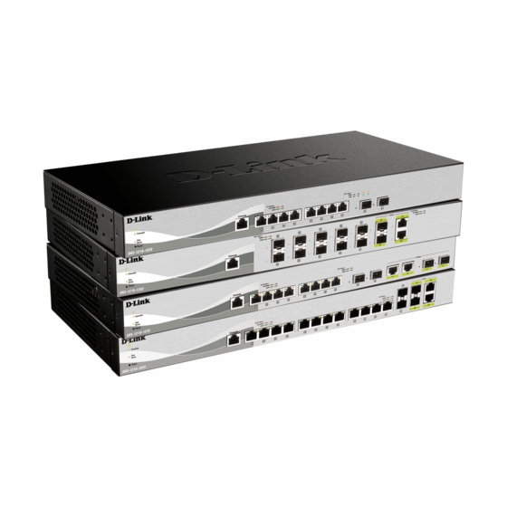
QoS and versatile management. Flexible Port Configurations: The DXS-1210 Series is D-Link’s latest 10G switch which provides 8-port, 10-port 10GBASE-T and 12-port SFP+ models. The DXS-1210 Series switches, have the advantage of using intuitive feature-rich software and utilizing a neat and simplified Web GUI allowing users to access and configure the Switch from everywhere via a web browser. -
Page 9: Dxs-1210-10Ts
8-Port 10GBASE-T and 2-Port SFP + Fiber port L2 10 Gigabit Ethernet Switch. Front Panel Figure 1.1 – DXS-1210-10TS Front Panel Power LED : The Power LED lights up when the Switch is connected to a power source. Console: The console LED lights up when the console port is connected. -
Page 10: Rear Panel
D-Link DXS-1210 Series User Manual CAUTION: The MiniGBIC ports should use UL listed Optical Transceiver product, Rated Laser Class I. 3.3Vdc. Reset: By pressing the Reset button, the Switch will change back to the default configuration and all changes will be lost. -
Page 11: Dxs-1210-16Tc
D-Link DXS-1210 Series User Manual DXS-1210-16TC 12-Port 10G SFP+ fiber port, 2-port 10GBASE-T/SFP+ and 2-port 10BGASE-T/SFP+ combo port L2 10 Gigabit Ethernet Switch. Front Panel Figure 1.7 – DXS-1210-16TC Front Panel Power LED : The Power LED lights up when the Switch is connected to a power source. -
Page 12: Hardware Installation
D-Link DXS-1210 Series User Manual Hardware Installation This chapter provides unpacking and installation information for the D-Link DXS-1210 Series Switch. Safety Cautions To reduce the risk of bodily injury, electrical shock, fire and damage to the equipment, observe the following precautions: •... -
Page 13: Step 1: Unpacking
D-Link DXS-1210 Series User Manual • Install the power supply before connecting the power cable to the power supply. • Unplug the power cable before removing the power supply. • If the system has multiple sources of power, disconnect power from the system by unplugging all power cables from the power supplies. -
Page 14: Step 3 - Plugging In The Ac Power Cord
D-Link DXS-1210 Series User Manual Then, use the screws provided with the equipment rack to mount the switch in the rack. Figure 2.3 – Mount the Switch in the rack or chassis Step 3 – Plugging in the AC Power Cord The Switch can now be connected to the AC power. -
Page 15: Getting Started
This chapter introduces the management interface of D-Link DXS-1210 Series Switch. Management Options The D-Link DXS-1210 Series Switch can be managed through any port by using the Web-based Management, or through any PC using CLI commands. Each switch must be assigned its own IP Address, which is used for communication with the Web-Based Management or a SNMP network manager. -
Page 16: Smart Wizard
English. Figure 3.3 – Login Dialog Box Smart Wizard After a successful login, the Smart Wizard will guide you through essential settings of the D-Link DXS-1210 Series Switch. Please refer to the Smart Wizard Configuration section for details. Web-based Management By clicking the Exit button in the Smart Wizard, you will enter the Web-based Management interface. -
Page 17: Configuration
Smart Wizard Configuration After a successful login, the Smart Wizard will guide you through essential settings of the D-Link DXS-1210 Series Switch. If you do not plan to change anything, click Exit to leave the Wizard and enter the Web Interface. -
Page 18: User Accounts Settings
D-Link DXS-1210 Series User Manual Figure 4.2 – SNMP Settings in Smart Wizard User Accounts Settings The User Accounts Settings page allows you to quickly specify the user account function. Enter the User Name, Privilege, Password Type and Password. Click Apply & Save to save the configuration. -
Page 19: Web-Based Management
Click the D-Link logo at the upper-left corner of the screen to be redirected to the local D-Link website. Tool Bar > Save Menu The Save Menu provides Save Configuration and Save Log functions. -
Page 20: Tool Bar > Tool Menu
D-Link DXS-1210 Series User Manual Figure 4.6 – Save Configuration Destination: Select the destination to save the configuration to. Startup-config: Check the box to enable the startup configuration function. Click the Apply button to save your settings. Tool Bar > Tool Menu The Tool Menu offers global functions controls such as Reset, Reboot Device, Configuration Backup and Restore, Firmware Backup and Upgrade. -
Page 21: Firmware Upgrade & Backup > Firmware Upgrade From Http
D-Link DXS-1210 Series User Manual Firmware Upgrade & Backup > Firmware Upgrade from HTTP To upgrade the firmware of Switch from a firmware file, select a Source URL, firmware Destination URL and click Upgrade. The specified firmware file will be uploaded to the Switch via HTTP. -
Page 22: Configuration Upgrade & Backup > Configuration Restore From Tftp
D-Link DXS-1210 Series User Manual Figure 4.14 – Tool Menu > Configuration Upgrade & Backup > Configuration Restore from HTTP Startup-config: Check the box to enable the startup configuration function. Configuration Upgrade & Backup > Configuration Restore from TFTP To load the Switch’s configuration from a saved configuration file using TFTP, enter the TFTP server IP address, destination image and source URL, then click Restore. -
Page 23: Log Backup > Log Backup To Tftp
D-Link DXS-1210 Series User Manual Log Backup > Log Backup to TFTP To save the log to a file using TFTP, enter the TFTP server IP address and destination URL then click Backup. Figure 4.19 – Tool Menu > Log Backup > Log Backup to TFTP TFTP Server IP: Select IPv4 or IPv6 and enter the IP address. -
Page 24: Tool Bar > Smart Wizard
Tool Bar > Online Help The Online Help provides two ways of online support: D-link Support Site will lead you to the D-Link website where you can find online resources such as updated firmware; User Guide can offer an immediate reference for the feature definition or configuration guide. - Page 25 D-Link DXS-1210 Series User Manual Figure 4.24 – User Guide Micro Site...
-
Page 26: Function Tree
D-Link DXS-1210 Series User Manual Function Tree All configuration options on the switch are accessed through the Setup menu on the left side of the main window. Click on the setup item that you want to configure. The following sections provide more detailed description of each feature and function. -
Page 27: System > Peripheral
D-Link DXS-1210 Series User Manual Figure 4.27 – System > System Information System > Peripheral The Peripheral page allows user to configure the environment trap settings and environment temperature threshold settings. System Information Settings: Enter a System Name, System Location and System Contact. -
Page 28: System > Port Configuration > Port Status
D-Link DXS-1210 Series User Manual Figure 4.29 – System > Port Configuration > Port Settings From Port / To Port: Select the appropriate port range to be configured. State: Enable or disable the physical port. Auto Downgrade: To enable or disable automatically downgrading the advertised speed, in-case a link cannot be established at the available speed. -
Page 29: System > Port Configuration > Error Disable Settings
D-Link DXS-1210 Series User Manual Figure 4.30 – System > Port Configuration > Port Status System > Port Configuration > Error Disable Settings The Error Disable Settings page allows you to configure the sending of SNMP notifications for error disable state. -
Page 30: System > Port Configuration > Jumbo Frame
D-Link DXS-1210 Series User Manual System > Port Configuration > Jumbo Frame The Jumbo Frame page allows you to view and configure the Jumbo Frame size and settings. Jumbo frames are Ethernet frames with more than 1,518 bytes of payload. The Switch supports jumbo frames with a maximum frame size of up to 9216 bytes. -
Page 31: System > System Log > System Log Server Settings
D-Link DXS-1210 Series User Manual System > System Log > System Log Server Settings The System Log Server Settings page allows you to view and configure the system log’s server settings. Figure 4.34 – System > System Log > System Log Server Settings IP Address: Select and enter the IPv4 address or IPv6 Address. -
Page 32: System > Time And Sntp > Time Zone Settings
D-Link DXS-1210 Series User Manual Time (HH:MM:SS): Enter the current time in hours, minutes, and seconds. Data (DD/MM/YYYY): Enter the current day, month, and year to update the system clock. Click the Apply button to save your settings. System > Time and SNTP > Time Zone Settings The Time Zone Settings page allows you to configure time zones and Daylight Saving Time settings for SNTP. -
Page 33: System > Time And Sntp > Sntp Settings
D-Link DXS-1210 Series User Manual From: Year – Select the year that the daylight saving time will start. From: Time In HH MM – Select the time of the day that daylight saving time will start. To: Date of the Month – Select the date of the month that daylight saving time will end. -
Page 34: Management > User Accounts Settings
D-Link DXS-1210 Series User Manual Range Name: Enter a name for the time range. The name can be up to 32 characters long. From Week / To Week: Select the starting and ending days of the week that will be used for this time range. -
Page 35: Management > Password Encryption
D-Link DXS-1210 Series User Manual Management > Password Encryption The Password Encryption page allows you to enable or disable password encryption. Figure 4.42 – Management > Password Encryption Password Encryption State: Specify to enable or disable the password encryption. Password Type: Specify the password encryption type to Encrypted-SHA1 or Encrypted-MD5. -
Page 36: Management > Snmp > Snmp View Table Settings
D-Link DXS-1210 Series User Manual SNMP Authentication Trap: Tick this option to control the sending of SNMP authentication failure notifications. An authenticationFailuretrap is generated when the device receives an SNMP message that is not properly authenticated. The authentication method depends on the version of SNMP being used. For SNMPv1 or SNMPv2c, authentication failure occurs if packets are formed with an incorrect community string. -
Page 37: Management > Snmp > Snmp Group Table Settings
D-Link DXS-1210 Series User Manual Figure 4.45 – Management > SNMP > SNMP Community Table Settings Key Type: Select the key type for the SNMP community. Select either Plain Text or Encrypted. Community Name: Select an alphanumeric string of up to 32 characters that is used to identify members of an SNMP community. -
Page 38: Management > Snmp > Snmp Engine Id Local Settings
D-Link DXS-1210 Series User Manual SNMPv2c - SNMPv2 supports both centralized and distributed network management strategies. It includes improvements in the Structure of Management Information (SMI) and adds some security features. SNMPv3 - SNMPv3 provides secure access to devices through a combination of authentication and encryption. -
Page 39: Management > Snmp > Snmp Host Table Settings
D-Link DXS-1210 Series User Manual User Name: Enter a SNMP user name of up to 32 characters. Group Name: Enter the SNMP group of the SNMP user. SNMP Version: Select the SNMP version of the user. The options to choose are v1, v2c and v3. -
Page 40: Management > Rmon > Rmon Global Settings
D-Link DXS-1210 Series User Manual AuthNoPriv – Select to require authorization, but with no encryption of packets sent between the Switch and a remote SNMP manager. AuthPriv – Select to require authorization, and packets sent between the Switch and a remote SNMP manger will be encrypted. -
Page 41: Management > Rmon > Rmon Alarm Settings
D-Link DXS-1210 Series User Manual The History Control Configuration contains the following fields: Port: Select the port from which the RMON information was taken. Index (1 - 65535): Indicates the history control entry number. Buckets Requested (1 ~ 50): Enter the number of buckets that the device saves. -
Page 42: Management > Telnet/Web
D-Link DXS-1210 Series User Manual Figure 4.54 – Management > RMON > RMON Event Settings The RMON Events Page contains the following fields: Index (1~ 65535): Enter the event index. Description: Enter an event description. Type: Select the event type. The possible values are: None –... -
Page 43: Management > Session Timeout
30 minutes. Click the Apply button to save your settings. Management > D-Link Discover Protocol Settings The D-Link Discover Protocol Settings page allows you to configure and display D-Link Discovery Protocol (DDP). Figure 4.57 – Management > D-Link Discover Protocol Settings D-Link Discovery Protocol State: Enter the enable or disable the D-Link Discovery Protocol state. -
Page 44: L2 Features > Fdb > Static Fdb > Unicast Static Fdb
D-Link DXS-1210 Series User Manual L2 Features > FDB > Static FDB > Unicast Static FDB The Unicast Static FDB page allows you to view and configure the static unicast forwarding settings on the Switch. Figure 4.58 – L2 Features > FDB > Static FDB > Unicast Static FDB Port / Drop: Allows the selection of the port number on which the MAC address entered resides. -
Page 45: L2 Features > Fdb > Mac Address Table
D-Link DXS-1210 Series User Manual Aging Time: Enter the MAC address table’s aging time value. This value must be between 10 and 1000000 seconds. Entering 0 will disable MAC address aging. By default, this value is 300 seconds. Aging Destination Hit: Select to enable or disable the aging destination hit function. -
Page 46: L2 Features > 802.1Q Vlan
D-Link DXS-1210 Series User Manual Click the Clear All button to clear all dynamic MAC addresses. Click the View All button to display all the MAC addresses recorded in the MAC address table. L2 Features > 802.1Q VLAN The 802.1Q VLAN page allows you to view and configure the VLAN settings on this switch. - Page 47 D-Link DXS-1210 Series User Manual Figure 4.65 – L2 Features > VLAN Interface Unit: Select the switch unit that will be used for this configuration. Click the VLAN Detail button to view more detailed information about the VLAN on the specific interface.
-
Page 48: L2 Features > Auto Surveillance Vlan > Auto Surveillance Properties
D-Link DXS-1210 Series User Manual Ingress Checking: Select to enable or disable the ingress checking function. Native VLAN: Tick the option to enable the native VLAN function. VID (1-4094): After ticking the Native VLAN check box, this option will be available. Enter the VLAN ID used for this configuration. -
Page 49: L2 Features > Auto Surveillance Vlan > Mac Settings And Surveillance Device
D-Link DXS-1210 Series User Manual Port Settings: From Port/To Port: Specify the port range used for the configuration. State: Specify to enable or disable the state of the port. Click the Apply button to save your settings. L2 Features > Auto Surveillance VLAN > MAC Settings and Surveillance Device The MAC Settings and Surveillance Device page is used to configure the user-defined surveillance device OUI and display the surveillance VLAN information. -
Page 50: L2 Features > Voice Vlan > Voice Vlan Port
D-Link DXS-1210 Series User Manual Figure 4.71 – L2 Features > Voice VLAN > Voice VLAN Global Settings Voice VLAN State: Select to enable or disable Voice VLAN. VLAN ID (1-4094): Enter the voice VLAN ID. The value is range from 1 to 4094. -
Page 51: L2 Features > Voice Vlan > Voice Vlan Device
D-Link DXS-1210 Series User Manual Figure 4.73 – L2 Features > Voice VLAN > Voice VLAN OUI OUI Address: Specify the OUI MAC address. Mask: Specify the OUI MAC address matching bitmask. Description: Enter the description for the user-defined OUI with a maximum of 32 characters. - Page 52 D-Link DXS-1210 Series User Manual for STP are also used for RSTP. This section introduces some new Spanning Tree concepts and illustrates the main differences between the two protocols. The IEEE 802.1 Multiple Spanning Tree (MSTP) provides various load balancing techniques by allowing multiple VLANs to be mapped to a single spanning tree instance, providing multiple pathways across the network.
-
Page 53: L2 Features > Stp > Stp Port Settings
D-Link DXS-1210 Series User Manual Priority (0-61440): Enter the STP priority value. This value is between 0 and 61440. By default, this value is 32768. The lower the value, the higher the priority. Click the Apply button to save your settings. - Page 54 D-Link DXS-1210 Series User Manual Figure 4.77 – L2 Features > STP > STP Port Settings From Port/To Port: Enter a consecutive group of ports to be configured starting with the selected port. Cost: This is the STP port cost, which is used to calculate the spanning tree topology. tf represents the relative interface bandwidth and is the desirability of the link.
-
Page 55: L2 Features > Stp > Mst Configuration Identification
D-Link DXS-1210 Series User Manual Hello Time: The interval between two transmissions of BPDU packets sent by the Root Bridge to indicate to all other switches that it is indeed the Root Bridge. The default value is 2. Click the Apply button to save your settings. -
Page 56: L2 Features > Stp > Mstp Port Information
D-Link DXS-1210 Series User Manual Figure 4.79 – L2 Features > STP > STP Instance Click the Edit button to re-configure the specific entry. L2 Features > STP > MSTP Port Information The MSTP Port Information page allows you to configure the MSTP Interface settings. - Page 57 D-Link DXS-1210 Series User Manual Click the Apply button to save your settings. NOTE: STP and LBD should be disabled on the ring ports before enabling ERPS. Enter instance ID 1 and click Apply to create ERPS physical ring. Then the following page will be displayed.
-
Page 58: L2 Features > Erps(G.8032) > Erps Profile
D-Link DXS-1210 Series User Manual Click the Apply button to save your settings. Click the Back button to return to the previous page. Click Show Status button to display the ERPS status information. Figure 4.84 – L2 Features > ERPS(G.8032) > ERPS – Show Status L2 Features >... -
Page 59: L2 Features > Loopback Detection
D-Link DXS-1210 Series User Manual Figure 4.87 – L2 Features > ERPS(G.8032) > ERPS Profile - Edit Revertive: Specifies whether to enable or disable to the original state after a failure, for example, when the RPL was blocked. Guard Time (10-2000): Specifies the guard time of the R-APS function. The value is between 10 and 2000 milliseconds. -
Page 60: L2 Features > Link Aggregation
D-Link DXS-1210 Series User Manual Enabled VLAN ID List: Enter the VLAN ID for loopback detection. This only takes effect when VLAN-based is selected in the Mode drop-down list. Interval (1-32767): Set a Loop Detection Interval between 1 and 32767 seconds. The default is 2 seconds. -
Page 61: L2 Features > L2 Multicast Control > Igmp Snooping > Igmp Snooping Settings
D-Link DXS-1210 Series User Manual L2 Features > L2 Multicast Control > IGMP Snooping > IGMP Snooping Settings With Internet Group Management Protocol (IGMP) snooping, the DXS-1210 Series Switch can make intelligent multicast forwarding decisions by examining the contents of each frame’s Layer 2 MAC header. - Page 62 D-Link DXS-1210 Series User Manual Figure 4.91 – L2 Features > L2 Multicast Control > IGMP Snooping > IGMP Snooping – Show Detail Click the Modify button to edit the information in the following window: Figure 4.92 L2 Features > L2 Multicast Control > IGMP Snooping > IGMP Snooping – Modify The following parameters can be configured: Fast Leave: Select to enable or disable the IGMP snooping fast leave function.
-
Page 63: L2 Features > L2 Multicast Control > Igmp Snooping > Igmp Snooping Groups Settings
D-Link DXS-1210 Series User Manual L2 Features > L2 Multicast Control > IGMP Snooping > IGMP Snooping Groups Settings The IGMP snooping Groups Settings page allows you to configure and view the IGMP snooping static group, and view IGMP snooping group. -
Page 64: L2 Features > L2 Multicast Control > Igmp Snooping > Igmp Snooping Statistics Settings
D-Link DXS-1210 Series User Manual Figure 4.94 – L2 Features > L2 Multicast Control > IGMP Snooping > IGMP Snooping Mrouter Settings VID (1-4094): Enter the VLAN ID in the range 1 to 4094. Configuration: Select the port configuration type. -
Page 65: L2 Features > L2 Multicast Control > Mld Snooping > Mld Snooping Setting
D-Link DXS-1210 Series User Manual Find Type: Select the interface to be searched. The options are VLAN and Port. VID (1-4094): Enter the VLAN ID. Click the Find button to locate a specific entry based on the information entered. Click the Find All button to view all the entries. - Page 66 D-Link DXS-1210 Series User Manual Figure 4.97 – L2 Features > L2 Multicast Control > MLD Snooping > MLD Snooping Setting – Show Detail The window displays the detail information about MLD snooping VLAN. Click the Modify button to edit the information in the following window.
-
Page 67: L2 Features > L2 Multicast Control > Mld Snooping > Mld Snooping Groups Setting
D-Link DXS-1210 Series User Manual L2 Features > L2 Multicast Control > MLD Snooping > MLD Snooping Groups Setting The MLD Snooping Groups Settings page allows you to configure and view the MLD snooping static group, and view MLD snooping group. -
Page 68: L2 Features > L2 Multicast Control > Mld Snooping > Mld Snooping Statistics Settings
D-Link DXS-1210 Series User Manual VID (1-4094): Enter the VLAN ID. Configuration: Select the port configuration type. Port: Select to configure the port as being connected to a multicast-enabled router. Forbidden Port: Select to configure the port as not being connected to a multicast-enabled router. -
Page 69: L2 Features > Lldp > Lldp Global Settings
D-Link DXS-1210 Series User Manual be flooded based on the VLAN domain. When selecting the Forward All option, all multicast packets will be flooded based on the VLAN domain. When selecting the Filter Unregistered option, registered packets will be forwarded based on the forwarding table and all unregistered multicast packets will be filtered. -
Page 70: L2 Features > Lldp > Lldp Port Settings
D-Link DXS-1210 Series User Manual Message TX Interval (5-32768): This parameter indicates the interval at which LLDP frames are transmitted on behalf of this LLDP agent. The default value is 30 seconds. Message TX Hold Multiplier (2-10): This parameter is a multiplier that determines the actual TTL value used in an LLDPDU. -
Page 71: L2 Features > Lldp > Lldp Basic Tlvs Settings
D-Link DXS-1210 Series User Manual Figure 4.105 – L2 Features > LLDP >LLDP Management Address List Management Address: Select IPv4, IPv6 or All address to be displayed. Click Find and the table will update and display the values required. Subtype: Displays the managed address subtype (e.g. MAC or IPv4) Address: Displays the IP address. -
Page 72: L2 Features > Lldp > Lldp Dot3 Tlvs Settings
D-Link DXS-1210 Series User Manual Figure 4.107 – L2 Features > LLDP > LLDP Dot1 TLVs Settings From Port / To Port: Select the range of ports to be configured. Port VLAN: Select to enable or disable the port VLAN ID TLV to send. The Port VLAN ID TLV is an optional fixed length TLV that allows a VLAN bridge port to advertise the port’s VLAN identifier (PVID) that will be... -
Page 73: L2 Features > Lldp > Lldp-Med Port Settings
D-Link DXS-1210 Series User Manual From Port/To Port: A consecutive group of ports may be configured starting with the selected port. MAC/PHY Configuration/Status: Select whether the MAC/PHY Configuration Status is enabled on the port. The possible field values are: Enabled: Enables the MAC/PHY Configuration Status on the port. -
Page 74: L2 Features > Lldp > Lldp Local Port Information
D-Link DXS-1210 Series User Manual Figure 4.110 – L2 Features > LLDP > LLDP Statistics Information The following statistics can be viewed: LLDP Statistics Information: Displays the counters that refer to the whole switch. Last Change Time: Displays the time of the last change. It also displays the amount of time that has elapsed since the change was detected. -
Page 75: L2 Features > Lldp > Lldp Neighbor Port Information
D-Link DXS-1210 Series User Manual Figure 4.111 – L2 Features > LLDP > LLDP Local Port Information Port: Displays the port number. Port ID Subtype: Displays the port ID subtype. Port ID: Displays the port ID (Unit number/Port number). Port Description: Displays the port description. -
Page 76: L3 Features > Arp > Arp Aging Time
D-Link DXS-1210 Series User Manual Figure 4.113 – L2 Features > LLDP > LLDP Neighbors Port Information Click the Find button to locate a specific entry based on the information entered. Click the Clear button to remove the specified port of LLDP neighbor port or click Clear All button to remove all LLDP neighbor ports. -
Page 77: L3 Features > Ipv4 Interface
D-Link DXS-1210 Series User Manual Figure 4.116 – L3 Features > ARP > ARP Table Interface VLAN (1-4094): Select and enter the interface’s VLAN ID. IP address: Select and enter the IP address to be displayed. Mask: Enter the mask address for the specified IP address. -
Page 78: L3 Features > Ipv4 Static/Default Route
D-Link DXS-1210 Series User Manual Click the Back button to return to the previous window. State: Select to enable or disable the IPv4 interface’s global state. Click the Apply button to save your settings. IP Settings: Get IP From: Select Static or DHCP. When the Static option is selected, users can enter the IPv4 address of this interface manually. -
Page 79: L3 Features > Ipv4 Route Table
D-Link DXS-1210 Series User Manual IP Address: Specify the network address for the IPv4 static route. Mask: Specify the mask address for the IPv4 static route. If this is a default route, select the Default Route checkbox. Gateway: Enter the gateway address for IPv4 route. If this is a default route, then this is the default gateway. -
Page 80: L3 Features > Ipv6 Neighbor
D-Link DXS-1210 Series User Manual Click the Find button to display the specific entry. Click the Detail button to view and configure more detailed settings for the IPv6 interface entry. After clicking the Detail button, the following window will be appeared. -
Page 81: L3 Features > Ipv6 Static/Default Route
D-Link DXS-1210 Series User Manual Figure 4.126 – L3 Features > IPv6 Neighbor Interface VLAN (1-4094): Enter the VLAN ID of the IPv6 neighbor. IPv6 Address: Specifies the neighbor IPv6 address. MAC Address: Specifies the link layer MAC address. Click the Apply button to save your settings. -
Page 82: Qos > Port Default Cos
D-Link DXS-1210 Series User Manual Figure 4.128 – L3 Features > IPv6 Route Table IPv6 Address: Select and enter the IPv6 address to display here. IPv6 Address/Prefix Length: Select and enter the IPv6 address and prefix length to display here. Select the Longer Prefixes option to display the route and all of the more specific routes. -
Page 83: Qos > Port Scheduler Method
D-Link DXS-1210 Series User Manual QoS > Port Scheduler Method The Port Scheduler Method page allows you to view and configure the port scheduler method settings. Figure 4.130 – QoS > Port Scheduler Method From Port / To Port: Select the range of ports to be configured. -
Page 84: Qos > Cos To Queue Mapping
D-Link DXS-1210 Series User Manual From Port / To Port: Select the range of ports to be configured. Queue ID: Select the queue ID value. The range is between 0 and 7. WRR Weight (0-127): Enter the WRR weight value. The value is between 0 and 127. -
Page 85: Qos > Queue Rate Limiting
D-Link DXS-1210 Series User Manual limit for ingress packets is configured. When Output is selected, the rate limit for egress packets is configured. Rate Limit: Enter the Rate Limit for the specified port. When Bandwidth is selected, enter the input/output bandwidth value used in the space provided. -
Page 86: Qos > Dscp Cos Mapping
D-Link DXS-1210 Series User Manual Figure 4.135 – QoS > Port Trust State From Port / To Port: Select the range of ports to be configured. Trust State: Select the trust state to be CoS or DSCP. Click the Apply button to save your settings. -
Page 87: Acl > Acl Configuration Wizard
D-Link DXS-1210 Series User Manual Click the Apply button to save your settings. ACL > ACL Configuration Wizard The ACL Configuration Wizard page allows you to create a new ACL access list or configure an existing ACL access list. Figure 4.137 – ACL > ACL Configuration Wizard Create: Select Create and enter the ACL Name with a maximum of 32 characters. - Page 88 D-Link DXS-1210 Series User Manual Figure 4.139 – ACL > ACL Configuration Wizard – Create MAC ACL The Add ACL Profile MAC ACL contains the following fields: Sequence No.(1-65535): Select the ACL rule number. The value is between 1 and 65535. Select Auto Assign to automatically generate an ACL rule number for this entry.
- Page 89 D-Link DXS-1210 Series User Manual To define the IPv4 ACL: Select IPv4 and then click the Next button. Click the IPv4 Address, Port, IPv4 DSCP and TCP Flag tabs to display the following page: Figure 4.140 – ACL > ACL Configuration Wizard – Create IPv4 ACL Sequence No.
- Page 90 D-Link DXS-1210 Series User Manual Destination Port: Select the destination port value. IP Precedence: Select the IP precedence value. Options to choose from are 0 (routine), 1 (priority), 2 (immediate), 3 (flash), 4 (flash-override), 5 (critical), 6 (internet), and 7 (network).
- Page 91 D-Link DXS-1210 Series User Manual Action: Select the action for the rule. The values are Permit and Deny. After selecting ICMP as the Protocol Type, click the IPv4 Address, ICMP and IPv4 DSCP tabs to display the following page: Figure 4.143 – ACL > ACL Configuration Wizard – Create IPv4 ACL-ICMP Source: Select the source information.
- Page 92 D-Link DXS-1210 Series User Manual Figure 4.144 – ACL > ACL Configuration Wizard – Create IPv4 ACL-EIGRP Source: Select the source information. The values are Any, Host and IP. Destination: Select the destination information. The values are Any, Host and IP.
- Page 93 D-Link DXS-1210 Series User Manual Figure 4.145 – ACL > ACL Configuration Wizard – Create IPv4 ACL-ESP Source: Select the source information. The values are Any, Host and IP. Destination: Select the destination information. The values are Any, Host and IP.
- Page 94 D-Link DXS-1210 Series User Manual Figure 4.146 – ACL > ACL Configuration Wizard – Create IPv4 ACL-GRE Fragments: Select the Fragments option to include packet fragment filtering. Source: Select the source information. The values are Any, Host and IP. Destination: Select the destination information. The values are Any, Host and IP.
- Page 95 D-Link DXS-1210 Series User Manual Figure 4.147 – ACL > ACL Configuration Wizard – Create IPv4 ACL-IGMP Fragments: Select the Fragments option to include packet fragment filtering. Source: Select the source information. The values are Any, Host and IP. Destination: Select the destination information. The values are Any, Host and IP.
- Page 96 D-Link DXS-1210 Series User Manual Figure 4.148 – ACL > ACL Configuration Wizard – Create IPv4 ACL-OSPF Fragments: Select the Fragments option to include packet fragment filtering. Source: Select the source information. The values are Any, Host and IP. Destination: Select the destination information. The values are Any, Host and IP.
- Page 97 D-Link DXS-1210 Series User Manual Figure 4.149 – ACL > ACL Configuration Wizard – Create IPv4 ACL-PIM Fragments: Select the Fragments option to include packet fragment filtering. Source: Select the source information. The values are Any, Host and IP. Destination: Select the destination information. The values are Any, Host and IP.
- Page 98 D-Link DXS-1210 Series User Manual Figure 4.150 – ACL > ACL Configuration Wizard – Create IPv4 ACL-VRRP Fragments: Select the Fragments option to include packet fragment filtering. Source: Select the source information. The values are Any, Host and IP. Destination: Select the destination information. The values are Any, Host and IP.
- Page 99 D-Link DXS-1210 Series User Manual Figure 4.151 – ACL > ACL Configuration Wizard – Create IPv4 ACL-IP in IP Fragments: Select the Fragments option to include packet fragment filtering. Source: Select the source information. The values are Any, Host and IP.
- Page 100 D-Link DXS-1210 Series User Manual Figure 4.152 – ACL > ACL Configuration Wizard – Create IPv4 ACL-PCP Fragments: Select the Fragments option to include packet fragment filtering. Source: Select the source information. The values are Any, Host and IP. Destination: Select the destination information. The values are Any, Host and IP.
- Page 101 D-Link DXS-1210 Series User Manual Figure 4.153 – ACL > ACL Configuration Wizard – Create IPv4 ACL-Protocol ID Fragments: Select the Fragments option to include packet fragment filtering. Source: Select the source information. The values are Any, Host and IP.
- Page 102 D-Link DXS-1210 Series User Manual Figure 4.154 – ACL > ACL Configuration Wizard – Create IPv4 ACL-None Fragments: Select the Fragments option to include packet fragment filtering. Source: Select the source information. The values are Any, Host and IP. Destination: Select the destination information. The values are Any, Host and IP.
- Page 103 D-Link DXS-1210 Series User Manual Figure 4.155 – ACL > ACL Configuration Wizard – Create IPv6 ACL-TCP Source Port: Select the source port value. Destination Port: Select the destination port value. IPv6 DSCP (0-63): Select the DSCP value. And the range is between 0 and 63.
- Page 104 D-Link DXS-1210 Series User Manual Figure 4.156 – ACL > ACL Configuration Wizard – Create IPv6 ACL-UDP Source Port: Select the source port value. Destination Port: Select the destination port value. Source: Select the source information. The values are Any, Host and IP.
- Page 105 D-Link DXS-1210 Series User Manual Figure 4.157– ACL > ACL Configuration Wizard – Create IPv6 ACL-ICMP Source: Select the source information. The values are Any, Host and IP. Destination: Select the destination information. The values are Any, Host and IP.
- Page 106 D-Link DXS-1210 Series User Manual Figure 4.158 – ACL > ACL Configuration Wizard – Create IPv6 ACL-Protocol ID Source: Select the source information. The values are Any, Host and IP. Destination: Select the destination information. The values are Any, Host and IP.
- Page 107 D-Link DXS-1210 Series User Manual After selecting PCP as the Protocol Type, click the IPv6 Address, IPv6 DSCP and Flow Label tabs to display the following page: Figure 4.160 – ACL > ACL Configuration Wizard – Create IPv6 ACL-PCP Source: Select the source information. The values are Any, Host and IP.
- Page 108 D-Link DXS-1210 Series User Manual Figure 4.161 – ACL > ACL Configuration Wizard – Create IPv6 ACL-SCTP Source: Select the source information. The values are Any, Host and IP. Destination: Select the destination information. The values are Any, Host and IP.
-
Page 109: Acl > Acl Access List
D-Link DXS-1210 Series User Manual Source: Select the source information. The values are Any, Host and IP. Destination: Select the destination information. The values are Any, Host and IP. DSCP (0-63): Enter the DSCP value. And the range is between 0 and 63. -
Page 110: Acl > Acl Interface Access Group
D-Link DXS-1210 Series User Manual ACL > ACL Interface Access Group The ACL Interface Access Group page allows you to view and configure the interface access group settings. Figure 4.165 – ACL > ACL Interface Access Group From Port / To Port: Select the range of ports to be configured. -
Page 111: Security > Port Security > Port Security Global Settings
D-Link DXS-1210 Series User Manual Security > Port Security > Port Security Global Settings The Port Security Global Settings page allows you to view and configure the global port security settings. Port Security is a feature that prevents unauthorized computers (with source MAC addresses) unknown to the Switch from connection and gaining access to the network. -
Page 112: Security > Port Security > Port Security Address Entries
D-Link DXS-1210 Series User Manual State: Select to enable or disable the port security state of specified ports. Maximum (1-6556): Enter the maximum number of secure MAC addresses that will be allowed on the specified ports. The value is between 1 and 6656. -
Page 113: Security > 802.1X > 802.1X Port Settings
D-Link DXS-1210 Series User Manual Click the Apply button to save your settings. Security > 802.1X > 802.1X Port Settings The 802.1X Port Settings page allow you to configure the port settings. Figure 4.171 – Security > 802.1X > 802.1X Port Settings From Port / To Port: Select the range of ports to be configured. -
Page 114: Security > 802.1X > Authentication Sessions Information
D-Link DXS-1210 Series User Manual Click the Apply button to save your settings. Security > 802.1X > Authentication Sessions Information The Authentication Sessions Information page is used to view and configure the authentication session information. Figure 4.172 – Security > 802.1X > Authentication Sessions Information From Port / To Port: Select the port to be queried. -
Page 115: Security > 802.1X > Authenticator Diagnostics
D-Link DXS-1210 Series User Manual Security > 802.1X > Authenticator Diagnostics The authenticator Diagnostics is used to view and clear the authenticator diagnostics information. Figure 4.175 – Security > 802.1X > Authenticator Diagnostics Port: Select the port to be queried. -
Page 116: Security > Radius > Radius Server Settings
D-Link DXS-1210 Series User Manual Dead Time: Enter the dead time value here. This value must be between 1 and 1440 minutes. By default, this value is 0 minutes. When this option is 0, the unresponsive server will not be marked as dead. This setting can be used to improve the authentication processing time by setting the dead time to skip the unresponsive server host entries. -
Page 117: Security > Radius > Radius Statistic
D-Link DXS-1210 Series User Manual Click the Apply button to save your settings. Security > RADIUS > RADIUS Statistic The RADIUS Statistic page is used to view and clear the RADIUS statistics information. Figure 4.181 – Security > RADIUS > RADIUS Statistic Group Server Name: Select the RADIUS group server name from this list here. -
Page 118: Security > Network Access Authentication > Network Access Authentication Port Settings
D-Link DXS-1210 Series User Manual General Settings: Deny MAC–Move: Select to enable or disable the Deny MAC-Move feature here. This option controls whether authenticated hosts can move between switch ports and whether a host configured for multi- authenticate mode can move to another port. -
Page 119: Security > Network Access Authentication > Network Access Authentication Sessions Information
D-Link DXS-1210 Series User Manual From Port / To Port: Select the range of ports to be configured. Host Mode: Select the host mode option that will be associated with the selected port(s) here. Options to choose from are Multi Host and Multi Auth. If the port is operated in the multi-host mode, and if one of the hosts is authenticated, then all other hosts are allowed to access the port. -
Page 120: Security > Dhcp Server Screening > Dhcp Server Screening Global Settings
D-Link DXS-1210 Series User Manual Security > DHCP Server Screening > DHCP Server Screening Global Settings DHCP Server Screening function allows you to restrict an illegal DHCP server by discarding DHCP packets from distrusted ports. Figure 4.186 – Security > DHCP Server Screening > DHCP Server Screening Global Settings DHCP Server Screening Global Settings: Trap State: Select to enable or disable the trap state. -
Page 121: Security > Safeguard Engine
Click the Apply button to save your settings. Security > Safeguard Engine D-Link’s Safeguard Engine is a robust and innovative technology that automatically throttles the impact of packet flooding into the switch's CPU. This function helps to protect the the Switch from being interrupted by malicious viruses or worm attacks. -
Page 122: Security > Traffic Segmentation Settings
D-Link DXS-1210 Series User Manual Click the Apply button to save your settings. Security > Traffic Segmentation Settings This feature provides administrators to limit traffic flow from a single port to a group of ports on a single Switch. This method of segmenting the flow of traffic is similar to using VLANs to limit traffic, but is more restrictive. -
Page 123: Security > Dos Attack Prevention Settings
D-Link DXS-1210 Series User Manual a storm event is cleared. Click the Apply button to save your settings. Storm Control Polling Settings: Interval (1-300): Enter the interval value. The range is from 1 to 300. Retries (0-360): Enter the retry value. The range is from 0 to 360. -
Page 124: Security > Ssl > Ssl Global Setting
D-Link DXS-1210 Series User Manual Figure 4.193 – Security > DoS Attack Prevention Settings DoS Attack Prevention Settings: DoS Type Selection: Tick the DoS type to be prevented. State: Select to enable or disable the DoS attack prevention state. Action: Select the action for the DoS attack. -
Page 125: Oam > Cable Diagnostics
D-Link DXS-1210 Series User Manual Figure 4.195 – Security > SSL > SSL Service Policy Policy Name: Enter a policy name for SSL. Click the Add button to save your settings. Click the Find button to locate a specific entry based on the information entered. -
Page 126: Monitoring > Statistics > Port
D-Link DXS-1210 Series User Manual Monitoring > Statistics > Port This page allows you to display the port traffic statistics. Figure 4.197 – Monitoring > Statistics > Port From Port / To Port: Select the range of ports to be configured. -
Page 127: Monitoring > Statistics > Port Counters
D-Link DXS-1210 Series User Manual Click the Back button to return to the previous window. Click the Refresh button to refresh the display table. Monitoring > Statistics > Port Counters The Port Counters page allows you to display port counter statistics. -
Page 128: Monitoring > Mirror Settings
D-Link DXS-1210 Series User Manual Figure 4.201 – Monitoring > Statistics > Counters From Port / To Port: Select the range of ports to be viewed. Click the Find button to locate a specific entry based on the information entered. -
Page 129: Green > Power Saving
D-Link DXS-1210 Series User Manual Figure 4.203 – Monitoring > Mirror Settings Session Number: Select the mirror session number for the entry. Destination: Select the destination port for mirror settings. Source: Select the range of ports to be the source port and Frame Type to be mirrored. -
Page 130: Green > Eee
D-Link DXS-1210 Series User Manual Click the Delete button to remove the specified entry. After clicking the Power Saving Shutdown Settings tab, the following page will appear. Figure 4.205 – Green > Power Saving – Shutdown Settings From Port / To Port: Select the range of ports to be configured. -
Page 131: Appendix A - Technical Specifications
1000BASE-T transceivers supported: internal universal power supply - DGS-712 (1000BASE-TX) Acoustic Value: SFP transceivers: - DXS-1210-10TS: 44.6dB (2 Fans) - DEM-310GT (1000BASE-LX, 10km) - DXS-1210-12TC: 44.9dB (2 Fans) - DEM-311GT (1000BASE-SX, 550m) - DXS-1210-12SC: 39.2dB (2 Fans) - DEM-312GT2 (1000BASE-SX, 2km) - DXS-1210-16TC: 39.2dB (2 Fans) -
Page 132: Safety Certifications
ERPS Loopback Detection Be able to classify packets according to 802.3ad Link Aggregation: follow contents: - DXS-1210-10TS: up to 8 groups per - 802.1p priority device and 8 ports per group - VLAN - DXS-1210-12TC: up to 8 groups per... -
Page 133: Security
D-Link DXS-1210 Series User Manual TCP/UDP port number 802.1p DSCP IPv6 traffic class IPv6 flow label Security Port Security: Support 64 MACs per port IP and MAC ACL Broadcast Storm Control D-Link Safeguard Engine DHCP Server Screening over IPv4 or...
Need help?
Do you have a question about the DXS-1210-10TS and is the answer not in the manual?
Questions and answers