Table of Contents
Advertisement
Available languages
Available languages
Quick Links
Advertisement
Table of Contents

Related Manuals for D-Link DXS-1100-10TS


Summary of Contents for D-Link DXS-1100-10TS
- Page 1 Quick Installation Guide Краткое руководство по установке EasySmart Switch with 8 10GBase-T ports and 2 10GBase-X SFP+ ports / Настраиваемый коммутатор EasySmart с 8 портами 10GBase-T и 2 портами 10GBase-X SFP+ DXS-1100-10TS...
-
Page 2: Package Contents
Introduction This Quick Installation Guide gives instructions for setting up the D-Link DXS-1100-10TS switch. The model you have purchased may appear slightly different from those shown in the illustrations. For more detailed information about the device, its components, making network connections and technical specifications, please refer to the User Manual. -
Page 3: Desktop Or Shelf Installation
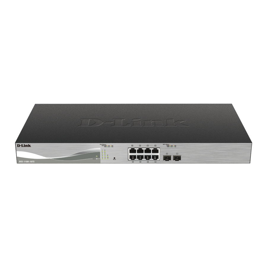
Front Panel Overview LED Indicators LED Indicative Colour Status Description Power Green Solid Light Power on Light off Power off Fan Error Solid light The fan has runtime failure and is brought offline Link/Act/Speed Green/Amber Solid Green When there is a secure 10Gbps connection (or link) at any of the ports (for port) Blinking Green When there is reception or transmission (i.e. -
Page 4: Rack Installation
Rack Installation The switch can be mounted in a standard size 19-inch rack, which can be placed in a wiring closet with other equipment. To install, attach the mounting brackets to the switch’s side panels (one on each side) and secure them with the screws provided. - Page 5 Plugging in the AC Power Cord with Power Cord Clip A) With the rough side facing down, insert the Tie Wrap into the hole below the power socket. B) Plug the AC power cord into the power socket of the Switch. C) Slide the Retainer through the Tie Wrap until the end of the cord.
- Page 6 D) Circle the tie of the Retainer around the power cord and into the locker of the Retainer. E) Fasten the tie of the Retainer until the power cord is secured. F) Users may now connect the power cord (AC 100/240 V) to an electrical outlet.
-
Page 7: Managing The Device
Managing the Device Management Options The DXS-1100-10TS can be managed through any port by using the Web-based Management. Each switch must be assigned its own IP Address, which is used for communication with the Web-Based Management or a SNMP network manager. The PC should have an IP address in the same subnet as the switch. -
Page 8: D-Link Network Assistant (Dna)
NOTE: please be sure to uninstall any existing DNA from your PC before installing the latest DNA. Additional Information For more detailed information on how to set up and configure the DXS-1100-10TS, please refer to the User Manual. -
Page 9: Комплект Поставки
или группу технической поддержки D-Link. Введение В этом кратком руководстве по установке даны инструкции по настройке коммутатора DXS-1100-10TS. Приобретенная модель может незначительно отличаться от показанной на рисунках. За более подробной информацией об устройстве, его компонентах, настройке подключения к сети и... -
Page 10: Установка Коммутатора
Обзор устройства Индикаторы Индикатор Цвет Режим Описание Power Зеленый Горит постоянно Устройство включено Не горит Устройство выключено Fan Error Красный Горит постоянно Ошибка в работе вентилятора, вентилятор отключен Link/Act/Speed (на Зеленый/ Горит постоянно К порту подключено устройство, скорость соединения порт) Оранжевый... -
Page 11: Подключение Питания
Установка в стойку Коммутатор может быть установлен в 19-дюймовую стойку, которая, как правило, размещается в серверной комнате вместе с другим оборудованием. Прикрепите кронштейны к боковым панелям коммутатора и зафиксируйте их с помощью входящих в комплект поставки винтов. Установите коммутатор в стойку и закрепите его с помощью винтов от стойки. Подключение... - Page 12 Закрепление кабеля питания с помощью фиксатора А) Вставьте кабельную стяжку в отверстие, расположенное под разъемом питания. В) Вставьте кабель в разъем питания. C) Наденьте фиксатор на кабельную стяжку.
- Page 13 D) Оберните ремешок фиксатора вокруг кабеля питания, затем проденьте ремешок в замок фиксатора. E) Зафиксируйте кабель, затянув ремешок фиксатора. F) Подключите кабель питания (AC 100/240 В) к соответствующему разъему на задней панели коммутатора и к электрической розетке.
-
Page 14: Управление Устройством
Управление устройством Функции управления Управлять устройством можно при помощи Web-интерфейса. Каждому коммутатору необходимо назначить свой IP-адрес, который используется для управления через Web-интерфейс или по SNMP. IP-адрес компьютера должен находиться в той же подсети, что и IP-адрес коммутатора. Доступ к коммутатору через... -
Page 15: Дополнительная Информация
вручную нажмите кнопку Exit. D-Link Network Assistant (DNA) D-Link Network Assistant (DNA) – это программа для обнаружения коммутаторов в том же сегменте сети, в котором находится ПК. Данная утилита поддерживает Windows 2000, Vista, XP, 7. Утилиту DNA можно скачать на сайте компании... -
Page 16: Технические Характеристики
Технические характеристики Аппаратное обеспечение Интерфейсы • 8 портов 10GBase-T • 2 порта 10GBase-X SFP+ Индикаторы • Power/Fan (на устройство) • Link/Activity/Speed (на порт) Функционал Стандарты и функции • IEEE 802.3u 100Base-TX • IEEE 802.3ab 1000Base-T • IEEE 802.3az • IEEE 802.3an 10GBase-T •... - Page 17 Тел.: +7 (4912) 575-305...
Need help?
Do you have a question about the DXS-1100-10TS and is the answer not in the manual?
Questions and answers