Table of Contents
Advertisement
Advertisement
Table of Contents

Related Manuals for D-Link DXS-5000-54S


Summary of Contents for D-Link DXS-5000-54S
- Page 2 Information in this document is subject to change without notice. Reproduction in any manner whatsoever, without the written permission of D-Link Corporation, is strictly forbidden. Trademarks used in this text: D-Link and the D-LINK logo are trademarks of D-Link Corporation; Microsoft and Windows are registered trademarks of Microsoft Corporation.
-
Page 3: Intended Readers
This manual is intended for advanced level users that are familiar with network management concepts and terminology. For all practical reasons, the DXS-5000-54S, DQS-5000-32S, DQS-5000-54SQ28, and DQS-5000- 32Q28 will simply be referred to as the switch throughout this manual. -
Page 4: Safety Cautions
5000 Series Data Center Switches Hardware Installation Guide Safety Cautions To greatly reduce the risk of physical injury, electrical shock, fire, and damage to equipment, observe the following precautions. Observe and follow service markings: • Do not attempt to service any product, except when it is explained in the system’s documentation. •... -
Page 5: General Precautions For Rack-Mountable Products
5000 Series Data Center Switches Hardware Installation Guide • 115 V / 60 Hz is used mostly in North and South America as well as Far Eastern countries like as South Korea and Taiwan • 100 V / 50 Hz is used mostly in Eastern Japan and 100 V / 60 Hz in Western Japan •... - Page 6 5000 Series Data Center Switches Hardware Installation Guide • When unpacking a static-sensitive component from its shipping carton, do not remove the component from the antistatic packing material until ready to install the component in the system. Just before unwrapping the antistatic packaging, be sure to discharge static electricity from your body.
-
Page 7: Table Of Contents
Switch to a Server ..............................20 Switch Management ..............................21 Management Options ..............................21 Connecting to the Console Port ..........................21 Installing D-Link OS .............................. 23 Creating a User Account ..........................25 Configuring the IP Address..........................25 Installing Other Operating Systems Using ONIE ....................26 Appendix A - Technical Specifications ........................ -
Page 8: Introduction
Side Panel Switch Description The D-Link 5000 Series Data Center Switches are a series of high-performance switches that feature high port density, routing, and ultra-low latency, designed to be deployed as Top-of-Rack (ToR), End-of-Row (EoR), or leaf- spine switches in data center applications. Combined with ONIE support and increased cost-efficiency, the 5000 Series form a flexible long-term solution for managing and expanding data center infrastructures in a Software-defined Networking (SDN) environment. - Page 9 5000 Series Data Center Switches Hardware Installation Guide Port Description 100G QSFP28 Ports 32 100G fiber optic access ports. RJ-45 console port for accessing the command line interface (CLI) of this Console Port switch for configuration, management, and monitoring. Management Port RJ-45 port for out-of-band management to configure the switch without being connected to the network.
-
Page 10: Led Indicators
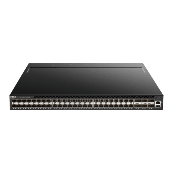
5000 Series Data Center Switches Hardware Installation Guide Figure 1-4 Front panel view of the DXS-5000-54S Port Description 10G SFP+ Ports 48 10G fiber optic access ports. 40G QSFP+ Ports 6 40G fiber optic access ports. Mini-USB console port for accessing the command line interface (CLI) of this Console Port switch for configuration, management, and monitoring. -
Page 11: Rear Panel
5000 Series Data Center Switches Hardware Installation Guide Description The fans are powered off. Solid green The fans are operating normally. Solid amber Indicates a fan has failed. Check the FAN Status LED on the rear panel to identify which fan is malfunctioning. Solid green The diagnostic test was successfully completed. -
Page 12: Fan Modules
5000 Series Data Center Switches Hardware Installation Guide The power supply modules are hot-swappable, they can be inserted and removed while the switch is powered on. This feature offers load-sharing, and enhances the reliability and capacity of this switch. However, in the event that a power failure might occur and no UPS is used, as a precaution, unplug the power cord from the switch. -
Page 13: Installation
5000 Series Data Center Switches Hardware Installation Guide Installation Installation Guidelines Installing the Switch into a Rack Installing Transceivers into the Transceiver Ports Installing Power Modules into the Power Module Slots Installing Fan Modules into the Fan Module Slots Installation Guidelines This section will discuss the hardware installation guidelines that the user must follow in order to properly and safely install this switch into the appropriate environment. -
Page 14: Installing Transceivers Into The Transceiver Ports
5000 Series Data Center Switches Hardware Installation Guide Figure 2-2 Installing the switch in a rack Installing Transceivers into the Transceiver Ports The 5000 Series supports a combination of Small Form-Factor pluggable (SFP) or Quad-Small Form-Factor pluggable (QSFP) ports, including SFP, SFP+, SFP28, QSFP+, and QSFP28. The SFP+ ports also support other transceiver form factors like SFP, SFP+, and WDM transceivers. -
Page 15: Installing Power Modules Into The Power Module Slots
5000 Series Data Center Switches Hardware Installation Guide Appendix A - Technical Specifications. Figure 2-3 Installing SFP transceivers Insert a compatible SFP transceiver into an available SFP port. Installing Power Modules into the Power Module Slots The power supply modules are hot-swappable and can be replaced during operation as long as the remaining module is installed and operating. -
Page 16: Removing A Power Supply
5000 Series Data Center Switches Hardware Installation Guide Figure 2-4 Green label port-side exhaust power supply module Figure 2-5 Blue label port-side intake power supply module Removing a Power Supply Hold the PSU handle and press the release latch to unlock the PSU from the switch. Pull the PSU module out of the switch. -
Page 17: Installing Fan Modules Into The Fan Module Slots
5000 Series Data Center Switches Hardware Installation Guide Installing Fan Modules into the Fan Module Slots The fan modules are hot swappable and can be replaced during operation as long as the remaining modules are installed and operating. Depending on whether you plan on positioning the ports in a hot or cold aisle, you can order a fan module with port- side intake (E) or port-side exhaust (I) airflow. -
Page 18: Installing A Fan Module
5000 Series Data Center Switches Hardware Installation Guide Figure 2-10 Removing a fan module Installing a Fan Module Align the fan module with the switch bay. Slide the fan module into the switch and push until it is firmly slotted into the bay. Secure the captive screw. -
Page 19: Grounding The Switch
5000 Series Data Center Switches Hardware Installation Guide Grounding the Switch It is recommended that a compliant system is installed as part of the chassis to reduce or prevent the risk of shock hazards, greatly reduce the risk of equipment damage or reduce the potential of data corruption. Warning: This equipment must be grounded. -
Page 20: Switch Connections
5000 Series Data Center Switches Hardware Installation Guide Switch Connections Switch to another Switch Switch to a Server Switch to another Switch Two or more switches can also be interlinked using fiber optic cables or direct-attached cables via the switch’s SFP+, SFP28, QSFP+, and QSFP28 access ports. -
Page 21: Switch Management
D-Link OS: For more detailed information about the D-Link OS CLI, refer to the 5000 Series CLI Reference Guide. Pluribus Networks OS: For more detailed information about the Pluribus Networks OS CLI, refer to the... - Page 22 After correctly configuring the terminal, plug the power cable into the power connector on the back of the switch. You will be presented with an option to select an operating system to boot the switch in, either D-Link OS or...
-
Page 23: Installing D-Link Os
NOTE: D-Link OS and all third-party operating systems must be activated first. Refer to the OS license activation information for more details on how to activate the OS. In the OS selection window, do not press any key. The system will automatically boot the Linux-based D-Link OS after a few seconds. - Page 24 Figure 4-5 D-Link OS Boot Screen If this is the first time logging into D-Link OS, enter the command sudo license install [activation code] to activate the operating system. Refer to the license activation information for the required information. The switch will need to be rebooted to continue.
-
Page 25: Creating A User Account
Creating a User Account When logging into the switch using D-Link OS, there is no preconfigured default username and password. One of the first and most important tasks will be to create user accounts. Logging in using a predefined administrator-level username will give the user privileged access to the switch's management software. -
Page 26: Installing Other Operating Systems Using Onie
Use the following procedure for installing/upgrading the switch to install the OS on the switch. Below is an example of installing D-Link OS over TFTP. In the OS selection, select ONIE and press Enter. - Page 27 5000 Series Data Center Switches Hardware Installation Guide ONIE:/ # onie-discovery-stop discover: ONIE embed mode detected. Stopping: discover... done. ONIE:/ # install_url tftp://192.168.3.15/onie-installer-x86_64-nc2x_rangely-1.0.3-rc-DLink-DXS-5000- Figure 4-12 ONIE OS Installation When the OS installation is successful, the switch will automatically reboot. The newly installed OS will now appear in the OS selection menu.
-
Page 28: Appendix A - Technical Specifications
5000 Series Data Center Switches Hardware Installation Guide Appendix A - Technical Specifications General DXS-5000-54S DQS-5000-32S DQS-5000-32Q28 DQS-5000-54SQ28 32 x 100G QSFP28 ports 48 x 25G SFP28 ports Interfaces 48 x 10G SFP+ ports 32 x 40G QSFP+ ports 1 x USB 2.0 port... - Page 29 5000 Series Data Center Switches Hardware Installation Guide Optional D-Link OS Activation Licenses DXS-5K-54S-DC-LIC License to activate the D-Link OS on the DXS-5000-54S DQS-5K-32S-DC-LIC License to activate the D-Link OS on the DQS-5000-32S DQS-5K-32Q28-DC-LIC License to activate the D-Link OS on the DQS-5000-32Q28...
- Page 30 5000 Series Data Center Switches Hardware Installation Guide DEM-435XT-DD 10GBASE-LRM, multi-mode, 200 m (with DDM) Optional WDM (Bidi) SFP+ Transceivers DEM-436XT-BXD 10GBASE-LR, single-mode, 20 km (TX: 1330 nm, RX: 1270 nm) (without DDM) DEM-436XT-BXU 10GBASE-LR, single-mode, 20 km (TX: 1270 nm, RX: 1330 nm) (without DDM) Optional 40G QSFP+ Transceivers DEM-QX01Q-SR4 40GBASE-SR4, multi-mode, OM3: 100 m / OM4: 150 m...
-
Page 31: Appendix B - Cables And Connectors
5000 Series Data Center Switches Hardware Installation Guide Appendix B - Cables and Connectors Console Cable A console cable is used when a user wants to connect to the console port of the switch, to access the command line interface. The following diagrams and tables show the standard RS-232-to-RJ-45/Mini-USB receptacle/connector and their pin assignments. -
Page 32: Regulatory Statements
5000 Series Data Center Switches Hardware Installation Guide Regulatory Statements Federal Communication Commission Interference Statement This equipment has been tested and found to comply with the limits for a Class A digital device, pursuant to part 15 of the FCC Rules. - Page 33 5000 Series Data Center Switches Hardware Installation Guide SICHERHEITSVORSCHRIFTEN Die folgenden allgemeinen Sicherheitsvorschriften dienen als Hilfe zur Gewährleistung Ihrer eigenen Sicherheit und zum Schutz Ihres Produkts. Weitere Details finden Sie in den Benutzeranleitungen zum Produkt. • Statische Elektrizität kann elektronischen Komponenten schaden. Um Schäden durch statische Aufladung zu vermeiden, leiten Sie elektrostatische Ladungen von Ihrem Körper ab, (z.
- Page 34 5000 Series Data Center Switches Hardware Installation Guide ISTRUZIONI PER LA SICUREZZA Le seguenti linee guida sulla sicurezza sono fornite per contribuire a garantire la sicurezza personale degli utenti e a proteggere il prodotto da potenziali danni. Per maggiori dettagli, consultare le istruzioni per l’utente del prodotto. •...
- Page 35 D-Link designs and builds its products to be as environmentally friendly as possible, by using recyclable, low toxic materials in both products and packaging. D-Link recommends that you always switch off or unplug your D-Link products when they are not in use. By doing so you will help to save energy and reduce CO2 emissions.
- Page 36 D-Link raadt aan om steeds uw D-Link producten uit te schakelen of uit de stekker te halen wanneer u ze niet gebruikt. Door dit te doen bespaart u energie en beperkt u de CO2-emissies.
- Page 37 D-Link og miljøet Hos D-Link forstår vi oss på og er forpliktet til å minske innvirkningen som vår drift og våre produkter kan ha på miljøet. For å minimalisere denne innvirkningen designer og lager D-Link produkter som er så miljøvennlig som mulig, ved å bruke resirkulerbare, lav-toksiske materialer både i produktene og forpakningen.
- Page 38 D-Link och miljön På D-Link förstår vi och är fast beslutna att minska den påverkan våra verksamheter och produkter kan ha på miljön. För att minska denna påverkan utformar och bygger D-Link sina produkter för att de ska vara så miljövänliga som möjligt, genom att använda återvinningsbara material med låg gifthalt i både produkter och förpackningar.
-
Page 39: Warranty & Technical Support
The customer must submit with the product as part of the claim a written description of the Hardware defect or Software nonconformance in sufficient detail to allow D-Link to confirm the same, along with proof of purchase of the product (such as a copy of the dated purchase invoice for the product) if the product is not registered. - Page 40 D-Link, the sellers, or the liquidators expressly disclaim their warranty obligation pertaining to the product. While necessary maintenance or repairs on your Product can be performed by any company, we recommend that you use only an Authorized D-Link Service Office. Improper or incorrectly performed maintenance or repair voids this Limited Warranty.
- Page 41 5000 Series Data Center Switches Hardware Installation Guide Product Registration Register your D-Link product online at http://support.dlink.com/register/ Product registration is entirely voluntary and failure to complete or return this form will not diminish your warranty rights.
- Page 42 This guide is only for initial configuration. Please refer to the user manual to learn more or visit http://www.mydlink.com for more information. Also feel free to contact us. U.S. and Canadian customers can contact D-Link Technical Support through our website. http://support.dlink.com Canada...
- Page 43 5000 Series Data Center Switches Hardware Installation Guide Europe customers TECHNICAL SUPPORT TECHNISCHE UNTERSTÜTZUNG ASSISTANCE TECHNIQUE ASISTENCIA TÉCNICA SUPPORTO TECNICO TECHNISCHE ONDERSTEUNING POMOC TECHNICZNA TECHNICKÁ PODPORA TECHNICKÁ PODPORA dlink.com/support TECHNIKAI TÁMOGATÁS TEKNISK SUPPORT TEKNISK SUPPORT TEKNISK STØTTE TEKNINEN TUKI ASSISTÊNCIA TÉCNICA ΤΕΧΝΙΚΉ...
- Page 44 Indonesia - www.dlink.co.id Malaysia - www.dlink.com.my Philippines - www.dlink.com.ph Vietnam - www.dlink.com.vn Korea customers Tel : +82-2-2028-1810 Monday to Friday 9:00am to 6:00pm Web : http://d-link.co.kr E-mail : g2b@d-link.co.kr New Zealand customers Tel: 0800-900-900 24/7 Technical Support Web: http://www.dlink.co.nz E-mail: support@dlink.co.nz...
- Page 45 08600 DLINK (for South Africa only) Monday to Friday 8:30am to 9:00pm South Africa Time Web: http://www.d-link.co.za E-mail: support@za.dlink.com D-Link Middle East - Dubai, U.A.E. customers Plot No. S31102, Jebel Ali Free Zone South, P.O.Box 18224, Dubai, U.A.E. Tel: +971-4-8809022...
- Page 46 5000 Series Data Center Switches Hardware Installation Guide +966 1121 70009 General Inquiries: info.sa@me.dlink.com Tech Support: support.sa@me.dlink.com Pakistan customers Islamabad Office: 61-A, Jinnah Avenue, Blue Area, Suite # 11, EBC, Saudi Pak Tower, Islamabad - Pakistan Tel.: +92-51-2800397, 2800398 Fax: +92-51-2800399 Karachi Office: D-147/1, KDA Scheme # 1, Opposite Mudassir Park, Karsaz Road,...
- Page 47 5000 Series Data Center Switches Hardware Installation Guide Morocco customers M.I.T.C Route de Nouaceur angle RS et CT 1029 Bureau N° 312 ET 337 Casablanca , Maroc Phone : +212 663 72 73 24 Email: support.na@me.dlink.com Lebanon RMA center customers Dbayeh/Lebanon PO Box:901589 Tel: +961 4 54 49 71 Ext:14...
- Page 48 Обновления программного обеспечения и документация доступны на Интернет-сайте D-Link. D-Link предоставляет бесплатную поддержку для клиентов в течение гарантийного срока. Клиенты могут обратиться в группу технической поддержки D-Link по телефону или через Интернет. Техническая поддержка компании D-Link работает в круглосуточном режиме ежедневно, кроме официальных праздничных дней. Звонок...
- Page 49 5000 Series Data Center Switches Hardware Installation Guide Офисы Россия Հայաստան Москва, Графский переулок, 14 Երևան, Դավթաշեն 3-րդ Тел. : +7 (495) 744-00-99 թաղամաս, 23/5 E-mail: mail@dlink.ru Հեռ.՝ +374 (10) 39-86-67 Էլ. փոստ՝ info@dlink.am Україна Київ, вул. Межигірська, 87-А Latvija Тел.: +38 (044) 545-64-40 Rīga, Lielirbes iela 27 E-mail: ua@dlink.ua...
- Page 50 Soporte Técnico Para Usuarios En Latino America Por favor revise el número telefónico del Call Center de su país en http://www.dlinkla.com/soporte/call-center Soporte Técnico de D-Link a través de Internet Horario de atención Soporte Técnico en www.dlinkla.com e-mail: soporte@dlinkla.com & consultas@dlinkla.com...
- Page 51 5000 Series Data Center Switches Hardware Installation Guide Clientes de Brasil Caso tenha dúvidas na instalação do produto, entre em contato com o Suporte Técnico D-Link. Acesse o site: www.dlink.com.br/suporte...
- Page 52 台灣服務時間:週一至週五 : 9:00~21:00 週六日及國定假日 ( 不含農曆春節 ) 10:00~19:00 台灣網站: http://www.dlink.com.tw 台灣電子郵件: dssqa_service@dlink.com.tw 產品保固期限、台灣區維修據點查詢,請參考 http://www.dlink.com.tw 網頁說明。 香港、澳門 D-Link 技術諮詢專線 香港技術諮詢服務專線 (852) 8100 8892 香港服務時間:週一至週五 9:00AM~1:00PM 及 2:00PM~6:00PM 週六 9:00AM~1:00PM 香港網站: http://www.dlink.com.hk 香港電子郵件: service@cn.synnex-grp.com 香港、澳門維修據點查詢請參考 http://www.dlink.com.hk/contact.html 網頁說明 如果您是其他地區的用戶,請參考 D-Link 網站 www.dlink.com 查詢全球各地分公司的 聯絡資訊以取得相關支援服務。...
- Page 53 5000 Series Data Center Switches Hardware Installation Guide Pelanggan Indonesia Update perangkat lunak dan dokumentasi pengguna dapat diperoleh pada situs web D-Link. Dukungan Teknis untuk pelanggan: Tel: 0800-14014-97 (Layanan Bebas Pulsa) Dukungan Teknis D-Link melalui Internet: Pertanyaan Umum: sales@id.dlink.com Bantuan Teknis: support@id.dlink.com Website : http://www.dlink.co.id 日本のお客様 この度は弊社製品をお買い上げいただき、誠にありがとうございま...
- Page 54 8. What category best describes your company? Aerospace Engineering Education Finance Hospital Legal Insurance/Real Estate Manufacturing Retail/Chain store/Wholesale Government Transportation/Utilities/Communication System house/company Other________________________________ 9. Would you recommend your D-Link product to a friend? Don't know yet 10.Your comments on this product? __________________________________________________________________________________________ __________________________________________________________________________________________...
Need help?
Do you have a question about the DXS-5000-54S and is the answer not in the manual?
Questions and answers