Icom IC-M700PRO Instruction Manual
Ssb radio telephone
Hide thumbs
Also See for IC-M700PRO:
- Service manual (74 pages) ,
- Servise manual (53 pages) ,
- Instruction manual (28 pages)
Table of Contents
Advertisement
Quick Links
Download this manual
See also:
Service Manual
Advertisement
Table of Contents

Related Manuals for Icom IC-M700PRO


Summary of Contents for Icom IC-M700PRO
- Page 1 INSTRUCTION MANUAL SSB RADIO TELEPHONE iM700PRO...
-
Page 2: Important
DEFINITION Personal injury, fire hazard or electric RWARNING shock may occur. Icom, Icom Inc. and the Icom logo are registered trademarks of Icom Incorporated (Japan) in Japan, the United States, the United Equipment damage may occur. CAUTION Kingdom, Germany, France, Spain, Russia, Australia, New Zealand, If disregarded, inconvenience only. -
Page 3: Table Of Contents
■ Antenna ····························································19 D MN-100/MN-100L ANTENNA MATCHERS 19 2 PANEL DESCRIPTION ·········································2 D AT-130 AUTOMATIC ANTENNA TUNER ···19 ■ Front panel ·························································2 D Non-Icom tuner ············································19 ■ Display ································································4 ■ Mounting ···························································20 D Mounting location ········································20 3 SELECTING A CHANNEL/FREQUENCY ············5 D Mounting example ·······································20... -
Page 4: Operating Rules And Guidelines
OPERATING RULES AND GUIDELINES ❑ CALL PROCEDURES ❑ LOGS Calls must be properly identified and time limits must q All distress, emergency and safety calls must be re- be respected. corded in complete detail. Log data activity is usu- ally recorded in 24 hour time. Universal Time (UTC) q Give your call sign each time you call another ves- is frequently used. -
Page 5: Panel Description
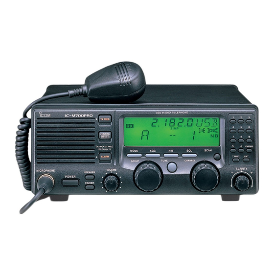
PANEL DESCRIPTION ■ Front panel This function is not installed in the IC-M700PRO. RADIO TELEPHONE iM 700PRO TX FREQ 2182KHz RESET [ALARM] [TX FREQ] CH/FREQ FOR ALARM TX MODE SCAN T ONLY TUNE GROUP CHANNEL CLARITY VOLUME MICROPHONE SPEAKER POWER DIMMER u ANTENNA TUNE SWITCH [TUNE] (p. - Page 6 PANEL DESCRIPTION ■ Front panel (Continued) This function is not installed in the IC-M700PRO. RADIO TELEPHONE iM 700PRO TX FREQ 2182KHz RESET [ALARM] [TX FREQ] CH/FREQ FOR ALARM TX MODE SCAN T ONLY TUNE GROUP CHANNEL CLARITY VOLUME MICROPHONE SPEAKER...
-
Page 7: Display
NOISE BLANKER INDICATOR (p. 9) Flashes while the connected antenna tuner, such Appears when the [NB] switch is turned ON. as Icom’s AT-130, is being tuned. o AGC OFF INDICATOR (p. 9) • Tuning starts when transmitting on a new frequency or Appears when the [AGC] switch is pushed to indi- pushing the [TUNE] switch. -
Page 8: Selecting A Channel/Frequency
SELECTING A CHANNEL/FREQUENCY ■ Memory mode/VFO mode The transceiver has 2 operating modes: memory mode and VFO mode. The memory mode is used to select preprogrammed marine channels in one of the 3 chan- nel groups; The VFO mode is used to select frequen- cies around preprogrammed channels. -
Page 9: D Scan Function
SELECTING A CHANNEL/FREQUENCY D Scan function The scan function allows you to automatically search for signals with a group of channels. There are 2 scan types (selectable in the set mode) as follows: Channel scan Scan operation q Rotate the [GROUP] selector to select the group you wish to scan. -
Page 10: Resetting The Cpu
SELECTING A CHANNEL/FREQUENCY ■ Resetting the CPU Under some circumstances, the transceiver’s internal CPU may cause erroneous indications on the display. If this happens, reset the CPU as follows: Group A, channel 1 is While pushing [ENT] and [0], push [POWER] to turn selected after resetting power ON. -
Page 11: Receive And Transmit
RECEIVE AND TRANSMIT ■ Basic voice receive and transmit w Select the desired channel to be received with the [GROUP] and [CHANNEL] selectors. • When receiving a signal, the S-meter shows the signal q Check the following in advance: strength. ➥... -
Page 12: Functions For Receive
RECEIVE AND TRANSMIT ■ Functions for receive D Squelch function The squelch function detects signals with voice com- Push [SQL] to toggle the function ON or OFF. ponents and squelches (mutes) unwanted signals, such as unmodulated beat signals. This provides D U P quiet standby. -
Page 13: Cw Operation
➥ FSK shift frequency and FSK polarity can be pin 3 adjusted in the set mode (p. 12). ➥ Some transceivers may operate 1.7 kHz higher Ground ACC(1) socket than the IC-M700PRO’s J2B mode, even when FSK terminal unit the same displayed frequencies are in use. -
Page 14: Set Mode
■ Set mode contents (1) Antenna tuner The transceiver has several tuner control systems for AT-130 (default) use with an optional Icom antenna tuner. Select the condition, depending on the antenna tuner you are using. AT-120 ☞ N OTE: An internal switch selection may be re- quired when using a non-Icom tuner (p. - Page 15 SET MODE (4) Scan speed Fastest scan speed Selects scan speed as follows: (default) (unit: sec./ch) Slowest scan speed Faster Slower (5) CW/FSK narrow filter Passband: This selects the passband width for CW (A1A), FSK 2.3 kHz/ 6 dB or J2B mode. (default) ☞...
- Page 16 (10) ID number setting for remote control NMEA ID: 1 When connecting an external controller, such as a personal computer, 2-digit ID codes are required to access the transceiver. The IC-M700PRO adopts the NMEA0183 format, and uses a “proprietary sentence” (default: 2) for remote control.
- Page 17 SET MODE (14) Group B channel inhibit Minimum number of This item allows you to set the number of usable channels set for channels in channel group B, up to a maximum of 50 Group B: 1 channels. Maximum number of channels set for Group B: 50 (default) (15) Group C channel inhibit...
-
Page 18: Connections And Installation
CONNECTIONS AND INSTALLATION ■ Connections on the rear panel R CAUTION: NEVER remove the line fuse from the DC power cable. External speaker Optional AT-130 12 V battery u TUNER RECEPTACLE q ANTENNA CONNECTOR (p. 19) Connects a control cable to an optional AT-130 Connects a 50 ø... -
Page 19: Connector Information
CONNECTIONS AND INSTALLATION ■ Connector information SPECIFICATIONS ACC(1) PIN PIN NAME DESCRIPTION CW and FSK keying input. Input level: Less than 0.6 V for transmit. Connects to ground. Connected in parallel with ACC(2) pin 2. Input/output pin. Ground level: –0.5 to 0.8 V SEND Goes to ground when transmitting. - Page 20 CONNECTIONS AND INSTALLATION ■ Connector information (Continued) REMOTE PIN PIN NAME DESCRIPTION SPECIFICATIONS Modulation input from an external Input impedance: 600 ø MOD+ terminal unit. Input level: Approx. 1.3 mV rms MOD– Coaxial ground for MOD+. AF detector output for an external Output impedance: 600 ø...
-
Page 21: Ground Connection
2 ground points may cause electrolysis. Undesirable ground points CAUTION: The IC-M700PRO has a negative (these points may cause electrolysis) ground. NEVER connect the IC-M700PRO to a • Engine block “positive ground system,” otherwise the transceiver • Keel bolt will not function. -
Page 22: Antenna
An optional OPC-566 is available Coaxial cable D Non-Icom tuner Some non-Icom tuners may be used with the IC- M700PRO. Please consult your dealer or marina if you wish to use one. The following internal settings may be required for connection. -
Page 23: Mounting
CONNECTIONS AND INSTALLATION ■ Mounting WARNING: NEVER D Mounting location mount the transceiver Select a location that provides easy access to the front overhead. The weight of the transceiver is approxi- panel for navigation safety, has good ventilation and mately 7.9 kg. (17.4 lb), but its apparent weight will is not subject to sea spray. -
Page 24: Disassembling The Transceiver
Follow the case and cover opening procedures Front sealing shown here when you want to adjust a setting for non-Icom tuner control. Rear sealing q Remove the 9 screws from the rear panel, then re- move the rear frame and rear sealing. -
Page 25: Troubleshooting
TROUBLESHOOTING What appears to be equipment malfunction may not be damaging or difficult to solve. Check the following chart before making any adjustments or sending the transceiver to an Icom Service Center. PROBLEM POSSIBLE CAUSE SOLUTION REF. ÷ ÷ p. 18 Power does not come ON Power cable is improperly connected. -
Page 26: Specifications
Icom transceiver. mum of insertion loss. Icom is not responsible for the destruction or damage to an Icom transceiver in the event the Icom transceiver is used with equipment that is not manufactured or approved by... - Page 27 MEMO...
- Page 28 A5472H-1EX-3a Printed in Japan 1-1-32 Kamiminami, Hirano-ku, Osaka 547-0003 Japan © 1997–2017 Icom Inc.
Need help?
Do you have a question about the IC-M700PRO and is the answer not in the manual?
Questions and answers