Table of Contents
Advertisement
Quick Links
Advertisement
Table of Contents

Related Manuals for Icom M700PROE


Summary of Contents for Icom M700PROE
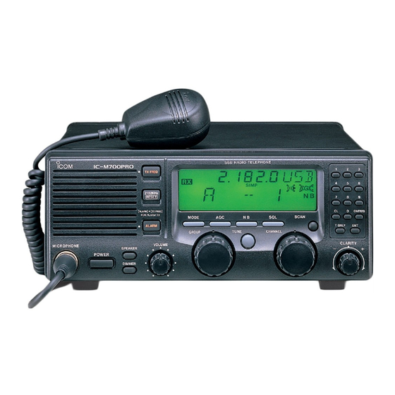
- Page 1 INSTRUCTION MANUAL SSB RADIO TELEPHONE iM700PRO...
-
Page 2: Important
RWARNING! NEVER mount the transceiver over- USE an Icom microphone and/or handset only (sup- head. The weight of the transceiver is approximately 8 plied or optional). Other brands may have different pin kg., but its apparent weight will increase several fold assignments and may damage the transceiver. -
Page 3: Versions
IN CASE OF EMERGENCY (for maritime operation) If your vessel requires assistance, contact other ves- sels and the Coast Guard by sending a distress call on 2182 kHz. ➀ Push [2182kHz] to select the emergency fre- 1. “MAYDAY, MAYDAY, MAYDAY.” quency. -
Page 4: Table Of Contents
3 SELECTING A CHANNEL/FREQUENCY ..5–7 D Non-Icom tuner ......19 I Memory mode/VFO mode ....5 I Mounting . -
Page 5: Operating Rules And Guidelines
OPERATING RULES AND GUIDELINES ❑ CALL PROCEDURES ❑ LOGS ➀ Calls must be properly identified and time limits must All distress, emergency and safety calls must be be respected. recorded in complete detail. Log data activity is usu- ally recorded in 24 hour time. Universal Time (UTC) ➀... -
Page 6: Panel Description
Tunes the connected tuner to the antenna. handset. • Activates only when an optional antenna tuner such as Icom’s AT-130 is connected. NOTE: No audio is output via the speaker when the microphone or handset is not connected. NOTE: When selecting “automatic tuning” in set... - Page 7 PANEL DESCRIPTION !1 KEYPAD !8 ALARM SWITCH [ALARM] (p. iii) ➥ Emits a distress alarm signal from the speaker. No function*. ➥ Transmits a distress alarm or alarm testing signal when pushed together with the [TX FREQ] Toggles between memory mode and VFO CH/FREQ switch.
-
Page 8: I Display
Appears when the [AGC] switch is pushed to indi- Flashes while the connected antenna tuner, such as cate the AGC function is deactivated. Icom’s AT-130, is being tuned. !1 MODE READOUT • Tuning starts when transmitting on a new frequency or Shows the selected operating mode (type of emis- pushing the [TUNE] switch. -
Page 9: Selecting A Channel/Frequency
SELECTING A CHANNEL/FREQUENCY I Memory mode/VFO mode The transceiver has 2 operating modes: memory mode and VFO mode. Memory mode is used to select pre- programmed marine channels in one of the 3 channel groups; VFO mode is used to select frequencies around preprogrammed channels. -
Page 10: D Scan Function
SELECTING A CHANNEL D Scan function The scan function allows you to automatically search channels within a group for signals. There are 2 scan types (selectable in set mode) as follows: Scan operation Channel scan ➀ Rotate the [GROUP] selector to select the group you wish to scan. -
Page 11: I Resetting The Cpu
SELECTING A CHANNEL I Resetting the CPU Under some circumstances the transceiver’s internal CPU may cause erroneous indications on the display. If this happens, reset the CPU as follows: While pushing [ENT] + [0], push [POWER] to turn Group A, channel 1 is power on. -
Page 12: Receive And Transmit
RECEIVE AND TRANSMIT I Basic voice receive and transmit ➁ Select the desired channel to be received with the [GROUP] and [CHANNEL] selectors. ➀ • When receiving a signal, the S-meter shows the signal Check the following in advance: ➥ Microphone is connected. strength. -
Page 13: I Functions For Receive
RECEIVE AND TRANSMIT I Functions for receive D Squelch function Push [SQL] to toggle the function on and off. The squelch function detects signals with voice com- ponents and squelches (mutes) unwanted signals such as unmodulated beat signals. This provides D U P quiet standby. -
Page 14: I Cw Operation
RECEIVE AND TRANSMIT I CW operation The transceiver has the following CW keying features CW key connection selectable in set mode as described on page 12. ➥ Full break-in (receiving is possible while transmitting) ➥ Delay keying (automatic transmission with keying) ➥... -
Page 15: Set Mode
(1) Connected antenna tuner The transceiver has several tuner control systems for AT-130 (default) use with an optional Icom antenna tuner. Select the condition depending on the connected antenna tuner. AT-120 NOTE: Internal switch selection may be required when using a non-Icom tuner (p. 19). - Page 16 SET MODE (4) Scan speed Fastest scan speed Selects scan speed as follows: (default) (unit: sec./ch) Slowest scan speed Faster Slower (5) CW/FSK narrow filter Passband: This item selects the passband width for CW (A1A), 2.3 kHz/–6 dB FSK or J2B mode. (default) ✍...
- Page 17 SET MODE (9) LCD contrast Lowest contrast The LCD contrast can be adjusted through 10 levels to suit transceiver mounting angle, location and am- bient lighting. (default: 7) Highest contrast (10) ID number setting for remote control NMEA ID: 1 When connecting an external controller such as a personal computer, 2-digit ID codes are required to access the transceiver.
- Page 18 SET MODE (14) Group B channel inhibit Minimum number of This item allow you to set the number of usable chan- channels set for nels in channel group B, up to a maximum of 50 Group B: 1 channels. Maximum number of channels set for Group B: 50 (default) (15) Group C channel inhibit...
-
Page 19: Connections And Installation
CONNECTIONS AND INSTALLATION I Connections on rear panel External speaker Optional AT-130 12 V battery q ANTENNA CONNECTOR (p. 19) u TUNER RECEPTACLE Connects a 50 Ω HF band antenna with a 50 Ω Connects a control cable to an optional AT-130 matched coaxial cable and a PL-259 plug. -
Page 20: I Connector Information
CONNECTIONS AND INSTALLATION I Connector information ACC(1) SPECIFICATIONS PIN PIN NAME DESCRIPTION CW and FSK keying input. Input level: Less than 0.6 V for transmit. Connects to ground. Connected in parallel with ACC(2) pin 2. Input/output pin. Ground level: –0.5 to 0.8 V SEND Goes to ground when transmitting. - Page 21 CONNECTIONS AND INSTALLATION REMOTE SPECIFICATIONS PIN PIN NAME DESCRIPTION Input impedance: 600 Ω Modulation input from an external MOD+ terminal unit. Input level: Approx. 1.3 mV rms MOD– Coaxial ground for MOD+. Output impedance: 600 Ω AF detector output for an external terminal unit.
-
Page 22: I Ground Connection
CONNECTIONS AND INSTALLATION I Ground connection The transceiver and antenna tuner MUST have an Good ground points adequate ground connection. Otherwise, the overall • Ship’s ground terminal efficiency of the transceiver and antenna tuner instal- • External ground plate lation will be reduced. Electrolysis, electrical shocks •... -
Page 23: I Antenna
An optional OPC-566 is available Coaxial cable D Non-Icom tuner Some non-Icom tuners may be used with the IC- M700PRO. Please consult your dealer or marina if you wish to connect one. The following internal set- tings may be required for connection. -
Page 24: I Mounting
CONNECTIONS AND INSTALLATION I Mounting R WARNING: D Mounting location NEVER mount the transceiver over- head. The weight of the transceiver is approximately Select a location that provides easy access to the front 8 kg., but its apparent weight will increase several panel for navigation safety, has good ventilation and is fold due to wave shocks or vibration. -
Page 25: I Installing Internal Options
Follow the case and cover opening procedures Front sealing shown here when you want to install an option or ad- just a setting for non-Icom tuner control. Rear sealing ➀ Remove the 9 screws from the rear panel, then re- move the rear frame and rear sealing. -
Page 26: Troubleshooting
TROUBLESHOOTING What appears to be equipment malfunction may not be damaging or difficult to solve. Check the following chart before making any adjustments or sending the trans- ceiver to an Icom Service Center. PROBLEM POSSIBLE CAUSE SOLUTION REF. Power does not come on •... -
Page 27: Specifications And Options
SPECIFICATIONS AND OPTIONS I Specifications TRANSMITTER • Output power: 150 W (60 W above 24 MHz) • Spurious emissions: –75 dB typical GENERAL • Carrier suppression: 65 dB typical • Frequency coverage: • Unwanted sideband suppression: 70 dB typical Receive 500 kHz–29.999 MHz •... - Page 28 Count on us! A-5472H-1EX Printed in Japan 1-1-32 Kamiminami, Hirano-ku, Osaka 547-0003 Japan Copyright 1997 by Icom Inc.
Need help?
Do you have a question about the M700PROE and is the answer not in the manual?
Questions and answers