
Related Manuals for Compit SOLARCOMP 951


Summary of Contents for Compit SOLARCOMP 951
- Page 1 OLAR CONTROLLER FOR SOLAR COLLECTORS Installation and Operating Instructions for model u7.x, Rev. 1, April 2014...
- Page 2 Safety Instructions Before installation read these Operation and Installation Instructions carefully and • become familiar with warranty terms and conditions. Faulty installation, use or main tenance of the controller will result in losing warranty rights. Any installation work can only be carried out after power supply has been discon •...
- Page 3 Introduction 951 has been designed for control of solar heating systems. OLAR Basic features of the controller include: Graphic display – it makes the operation of the controller easy. It helps to identify • the system operation variant used and system parameters. Heat meter –...
- Page 4 List of System Operation Variants Variant no. 1 Tank loaded from the solar panel – system with two sensors. Circulation pump control. Variant no. 2 Tank loaded from the solar panel – system with three sensors. Circulation pump control. Variant no. 3 Tank loaded from the solar panel –...
- Page 5 Variant no. 6 Two tanks loaded from the solar panel. Switching between tanks with a valve. Circulation pump control. Schemat 7 Two tanks loaded from the solar panel – system with two solar pumps. Circulation pump control. Variant no. 8 Tank loaded from the solar panel –...
- Page 6 Variant no. 11 Two tanks loaded from a two-panel unit. Two solar pump unit control. Selecting of the loaded tank with a diverter valve. Variant no. 12 Tank loaded from a two-panel unit. Two solar pump unit control. Circulation pump control.
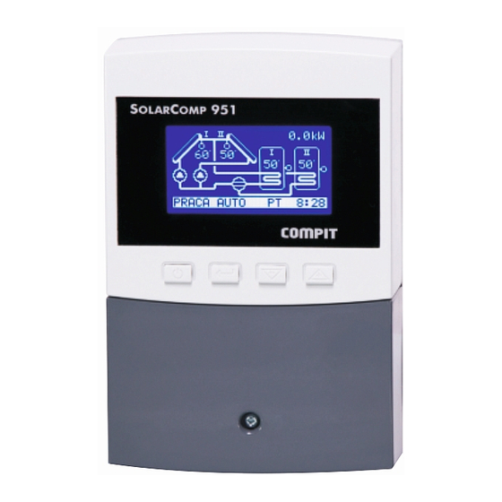
- Page 7 Control Panel Description 103mm display buttons connector cover cover holding screw Fig. 1: Control panel button arrangement Controller Operation Function Buttons ON/OFF button It is used to move up one menu level or to move back to the information window with the solar system diagram.
- Page 8 Basic Readings When the controller is on, the display shows the current system operation variant and readings of the measured temperature and power obtained from the collector. The information bar at the bottom of the display provides information current operation mode as well as the symbol of the current day of the week and time.
- Page 9 ΔT34 - T3-T4 temperature difference (variant no. 6). E.BOILER – meter of energy obtained from the CH boiler (variant no. 10). COMPIT Controller’s name. SolarComp 951 ver 4.0 Software version. Menu Structure When is pressed in the main window mode, the controller will display the...
- Page 10 Group A. Operation mode A. OPERATION MODE buttons to highlight the desired option √ AUTOMATIC MODE DEFROSTING and then press to save the change and return to the HOLIDAY MODE previous level. SHUT-DOWN AUTOMATIC MODE – the controller automatically controls the solar system. DEFROSTING –...
- Page 11 Group B. User Settings buttons to highlight the desired option and then press access the editing mode. Press to move up one menu level. B. USER SETTINGS Set temperature of the solar tank. 01. DHW TANK SET Default setting: 50°C. TEMPERATURE 50°C MIN 0...
- Page 12 B. USER SETTINGS Function blocking tank loading from the boiler when the solar 08. BOILER BLOCKED WHEN pump is working. PANEL ACTIVE Parameter available only in variant no. 3. Default setting: YES. B. USER SETTINGS Cooling with the boiler. 09. COOLING WITH BOILER If the solar tank is overheated, P2 pump activation starts heat discharge to the boiler.
- Page 13 Group C. Clock Settings buttons to highlight the desired option and then press access the editing mode. Press to move up one menu level. C. CLOCK SETTINGS Clock set-up. Repeat pressing to switch between day, 01. TIME hour and minute settings. WEDNESDAY 8:57.05 C.
- Page 14 Group D. Service Settings Service settings are protected with an access code. Entering the right code enables service settings editing. buttons to highlight the desired option and then press access the editing mode. Press to go up one menu level. D.
- Page 15 D. SERVICE SETTINGS Solar panel protection temperature; when exceeded, the solar 06.PANEL PROT. TEMP. pump is activated. This function protects the collector from (forced operation) overheating. Selecting 0 disables the function. 110°C Default setting: 110°C MIN 0 MAX 199 D. SERVICE SETTINGS Panel overheat temperature;...
- Page 16 D. SERVICE SETTINGS Solar pump operation time after starting panel defrosting 14.DEFROSTING TIME mode. Default setting: 120s 120s MIN 0 MAX 600 D. SERVICE SETTINGS Activating the detection of gravity heat convection from the 15.HEAT CONVECTION tank. DETECTION Default setting: NO. D.
- Page 17 D. SERVICE SETTINGS TYPE OF SOLAR THERMAL FLUID 20.SOLAR FLUID TYPE Water ERGOLID EKO -15°C 12 Transtherm EKO -35°C ERGOLID EKO -20°C 13 Termsol EKO concentrate MIN 0 MAX 22 ERGOLID EKO -25°C 14 Termsol EKO -15°C ERGOLID EKO -35°C 15 Termsol EKO -20°C Transtherm N -15°C 16 Termsol EKO -25°C...
- Page 18 D. SERVICE SETTINGS Controller’s address in the monitoring network. 26. RS485 NETWORK Default setting: 10 ADDRESS MIN 0 MAX 99 D. SERVICE SETTINGS Transmission speed. 27. RS485 NETWORK Default setting: 1200 SPEED 2400 MIN 1200 MAX 9600 D. SERVICE SETTINGS Restoring default settings.
- Page 19 System Operation Variants Variant no. 1 Tank loaded from the solar panel – system with two sensors. • Circulation pump control. • Tank loading The solar pump (P1) can work at the time set in parameter C.02 PANEL ACTIVE. Outside those times the solar pump’s operation is blocked. The tank is loaded until temperature T2 reaches the value set in parameter B.01 DHW TANK SET TEMPERATURE.
- Page 20 Variant no. 2 Tank loaded from the solar panel – system with three sensors. • Circulation pump control. • Tank loading The solar pump (P1) can work at the time set in parameter C.02 PANEL ACTIVE. Outside those hours the solar pump’s operation is blocked. The tank is loaded until temperatures T2 or T3 reaches the value set in parameter B.01 DHW TANK SET TEMPERATURE.
- Page 21 Variant no. 3 Tank loaded from the solar panel – system with three sensors. • Circulation pump control. • Additional heating of the tank with a heating coil. • Tank loading The loading of the tank is described on page 20. Heating coil operation The coil can additionally heat the tank at the times set in parameter C.03 HEATING COIL ON.
- Page 22 Variant no. 4 Tank loaded from the solar panel – system with three sensors. • Circulation pump control. • Excess tank heat discharge control. • Tank loading The loading of the tank is described on page 20. Heat discharge The temperature for starting the discharge of excess heat is determined in parameter D.08 T3 FOR HEAT DISCHARGE.
- Page 23 Variant no. 5 Tank loaded from the solar panel – system with three sensors. • Circulation pump control. • Heat transfer to auxiliary tank (based on temperature difference). • Tank loading The loading of the tank is described on page 20. Heat transfer Heat transfer depends on T3-T4 temperature difference and temperature T4.
- Page 24 Variant no. 6 Two tanks loaded from the solar panel. • Switching between tanks with a valve. • Circulation pump control. • Tank loading First the primary tank is loaded (1). The auxiliary tank (2) can be loaded when tank 1 temperature reaches the value set in parameter B.01 DHW TANK SET TEMPERATURE.
- Page 25 Variant no. 7 Two tanks loaded from the solar panel – system with two solar pumps. • Circulation pump control. • Tank loading First the primary tank is loaded (1). The auxiliary tank (2) can be loaded when tank 1 temperature reaches the value set in parameter B.01 DHW TANK SET TEMPERATURE.
- Page 26 Variant no. 8 Tank loaded from the solar panel – system with three sensors. • Solar tank loaded from an additional heat source based on temperature difference. • Circulation pump control. • Tank loading The loading of the tank is described on page 20. Tank heating from the CH boiler The set tank temperature, for which heating from the CH boiler is on, is determined in parameter B.07 BOILER LOADED DHW SET TEMPERATURE.
- Page 27 Variant no. 9 Tank loaded from the solar panel – system with three sensors. • Central heating return support control. • Circulation pump control. • Tank loading The loading of the tank is described on page 20. CH support CH support involves pre-heating of central heating return. This is done by means of the switching valve.
- Page 28 Variant no. 10 Tank loaded from the solar panel – system with two sensors. • P2 pump control. • Counting energy obtained from an auxiliary heat source (e.g. CH boiler). • Circulation pump control. • Tank loading The loading of the tank is described on page 19. P2 pump control P2 pump is started when the temperature measured with T2 sensor reaches the value set in parameter D09.
- Page 29 Variant no. 11 Two tanks loaded from two solar panels. • Tank loading The loading of tanks can take place at the times set in parameter C.02 PANEL ACTIVE. Outside those hours the pumps’ operation is blocked. First tank 1 is loaded. Loading of tank 2 can be started only after tank 1 has been heated up to the set temperature.
- Page 30 Variant no. 12 Tank loaded from two solar panels. • Circulation pump control. • Tank loading The loading of tanks can take place at the times set in parameter C.02 PANEL ACTIVE. Outside those hours the pumps’ operation is blocked. The tank is loaded until temperature T2 or T3 reaches the temperature set in parameter B.01 DHW TANK SET TEMPERATURE.
- Page 31 Variant no. 13 Tank loaded from the solar panel – system with three sensors. • Valve control diverting DHW through flow water heater. • Circulation pump control. • Tank loading The loading of the tank is described on page 20. Switching valve control The valve directs water through the flow water heater until temperature T3 reaches the value set in parameter B.04 HEATER SET TEMPERATURE.
- Page 32 Variant no. 14 Tank loaded from the solar panel – system with three sensors. • Pool loading control – system with a switching valve. • Circulation pump control. • Tank and pool loading Heating of the pool can be activated in parameter B.02 POOL HEATING ALLOWED. The pool can be heated when the temperature of the primary tank reaches the value set in parameter B.01 DHW TANK SET TEMPERATURE.
- Page 33 Variant no. 15 Tank loaded from two solar panels – system with a switching valve. • Circulation pump control. • Tank loading The controller switches the valve so that the tank is loaded from the warmer solar panel. Tank loading takes place as a function of temperature difference T1-T2 or T4-T2. If such difference exceeds the value set in D.02 PANEL-TANK DELTA FOR PUMP ON, then the controller starts P1 pump.
- Page 34 Mulfunctions Sensor failure signal can mean that the sensor is not connected. When several sensors fail, information on the last sensor failure is displayed. Solar panel sensor T1 failure. T1panel SENSOR Temperature reading is replaced by “!!!” FAILURE Tank sensor T2 failure. T2tank SENSOR Temperature reading is replaced by “!!!”...
- Page 35 Controller Installation and Commissioning Controller Mounting 103mm Undo the screw holding the • connector’s cover and remove the cover. Place the controller against the • wall and mark the location of display the bottom bolt. Mark the location of the top •...
- Page 36 Wiring Diagram NOTE! Any electrical connections must be made by duly authorised and qualified persons after power supply has been disconnected! 14 15 16 17 18 19 20 21 T1 T2 T3 T4 RS485 230V~ Zawór Grzałka 9 10 11 12 Uwaga! Podanie napięcia na zaciski 22 23 24 25 1-12 powoduje uszkodzenie regulatora...
- Page 37 Connection Diagram - Examples RS485 T2 T3 T4 A IMP 1 2 3 4 5 13 14 15 16 17 18 19 20 21 230V~ 50Hz 9 10 11 12 22 23 24 25 T2 T3 T4 Fig. 5: Sample Connection Diagram 951 model u7.x, Rev.
- Page 38 RS485 T2 T3 T4 A IMP 1 2 3 4 5 13 14 15 16 17 18 19 20 21 230V~ 50Hz 9 10 11 12 22 23 24 25 T2 T3 T4 Fig. 6: Connecting sensors and components to the controller in systems with a distribution valve. 951 model u7.x, Rev.
- Page 39 RS485 T2 T3 T4 A IMP 1 2 3 4 5 13 14 15 16 17 18 19 20 21 230V~ 50Hz 9 10 11 12 22 23 24 25 Stycznik Grzałka T2 T3 230V~ 50Hz Fig. 7: Connecting sensors and components in systems with a heating coil. Heating coil control requires a control coil 230V/50Hz compatible contactor.
- Page 40 Technical Data Power supply: 230V, 50Hz Current: I < 0.02A Fuse type WTA-F 2A Maximum rated current: 0.6A 2(0.6)A 2(0.6)A Protection type: IP20 Ambient temperature: 0..55°C Storage temperature: 0..55°C Relative humidity: 5 – 80% without vapour condensation Flow meter input: Frequency max.
- Page 41 Wielkoborska 77a 42-200 Częstochowa hereby declares that the product SolarComp 951 Microprocessor Controller meets the following requirements when applied in conformity with its intended use and according to the Manufacturer’s Installation and Operating Instructions: 1. Directive 2006/95/EC (LVD) of the European Parliament and of the Council of...
- Page 42 951 model u7.x, Rev. 1 OLAR...
- Page 43 NOTE: After selecting code 199, service parameters can be edited. SERVICE PARAMETERS SHOULD NOT BE MADE AVAILABLE TO THE USER! 951 model u7.x, Rev. 1 OLAR...
Need help?
Do you have a question about the SOLARCOMP 951 and is the answer not in the manual?
Questions and answers