Table of Contents
Advertisement
Quick Links
Advertisement
Table of Contents

Subscribe to Our Youtube Channel
Related Manuals for Compit R510


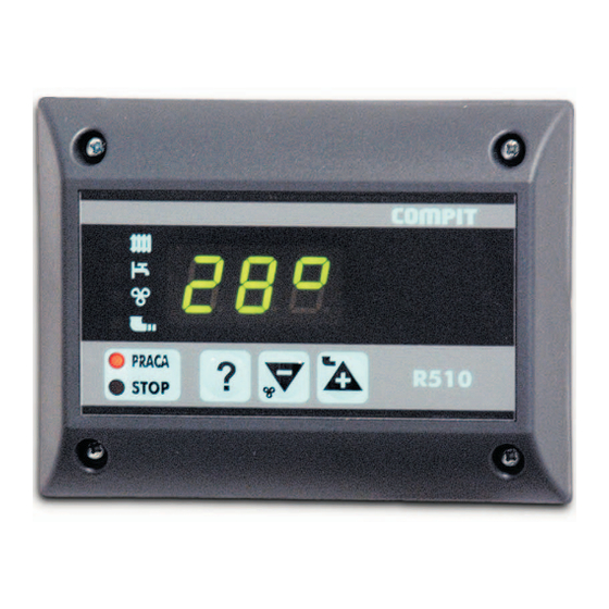
Summary of Contents for Compit R510
- Page 1 Operating Instructions COAL FEED SYSTEM BOILER WITH DO- MESTIC HOT WATER LOADING Sensor type: T2001 Outputs: 230V/50Hz Temperature setting range: 0 to +99°C Resolution: 1° www.compit.eu COMPIT, ul.Wielkoborska 77a, 42-200 Czêstochowa,tel./fax (34) 362 88 95 Str. 1...
- Page 2 Electric shock hazard! returned to a local distributor on purchase of new equipment. The wiring system to which COMPIT controller is con- Appropriate recycling should be carried out so as to avoid nected should be protected with appropriate safety fuses.
- Page 3 OPERATION R510 controller has been designed to maintain the boiler temperature and hot water tank temperature set by the user. The device controls the feeder, the blower and both central heating and domestic hot water pumps. The blower speed, which controls the amount of air used for combustion, can be freely adjusted.
-
Page 4: Operation Mode
Central heating boiler operation OPERATION mode When in the OPERATION mode, the feeder engages cyclically in START-UP mode order to feed in a new portion of coal for burning. The feeder oper- To proceed to the START-UP mode leave the SWITCH-OFF mode ating time and feeding break time are determined in the controller by pressing “PRACA/STOP”... -
Page 5: Maintenance Mode
MAINTENANCE mode THE BOILER IS SWITCHED OFF when the user presses In the MAINTENANCE mode the amount of the heat pro- the “PRACA/STOP” key and holds for over 3 seconds while in the duced is reduced to a minimum necessary for maintaining com- OPERATION or MAIINTENANCE mode. - Page 6 OPERATION WITH ROOM THERMOSTAT CAUTION: When the boiler temperature exceeds the maximum value, the CH and DHW pumps are enabled in order to reduce the Opening of the W terminal lowers the set temperature of the boiler temperature. boiler to minimum. The CH pump is also switched off after the DHW tank loading time set in F18 elapses –...
- Page 7 shorter by half and while in the MAINTENANCE mode the In the START-UP mode the “+” key is used to start the feeder and coal feed time is doubled. the “-” key is used to start the blower. A3 – boiler burn-out - the EMERGENCY relay is switched on. The LEDs are off.
- Page 8 MAINTENANCE mode – the OPERATION LED flashes. This mode Press the “?” key for the display to switch between the parameter allows for maintaining the combustion only. The controller number and its value. When the parameter number is displayed, controls the feeder and blower in cycles as set in “F7”, “F8” you will see letter F in the initial position followed by number of the and “F11”.
-
Page 9: List Of Parameters
LIST OF PARAMETERS F6 - Access code for other controller param- eters. NOTE: Inappropriate parameter setting may result in faulty boiler operation and in extreme situations in the boiler failure. User parameters – accessible with 99 code FACTORY DEFAULTS F7 - t0: feeder operating time in the OP- If the controls unit operation is disturbed due to faulty set- ERATION mode (setting range 1 to 500s in tings it is possible to set default parameters. - Page 10 SERVICE parameters – accessible with the service code F19 - feeder maximum temperature (setting range 0 to 99°C in 1°C steps). F13 - DHW priority, 0 - off, 1 - on, CH pump is off while loading the tank. F14 - set boiler temperature for loading the DHW tank (setting range 0 to 90°C in 1°C steps).
-
Page 11: Wiring Diagrams
WIRING DIAGRAMS INPUTS: 17, 18 - T3 sensor – DHW temperature 19, 20 - T2 sensor – feeder temperature 20, 21 - T1 sensor – CH boiler temperature 22, 23 - W input – room thermostat OUTPUTS: 1, 2 - 230 V~ power supply 3, 4 - main safety device (maximum 6,3 A fuse) - Page 12 display panel connection Fig. Controls unit connection diagram Pk2 Pk3 Str. 12...
- Page 13 MOUNTING The control panel is fitted to the boiler with four metal screws. The size of the panel and the position of mounting holes is pre- sented below: The controller consists of two modules: control panel and E510 operating module. The operating module is placed in a hous- ing to be mounted on the boiler.
- Page 14 In order to install the panel the following panel mounting hole should be made: PUTS R510 controller works with three sensors. The boiler, feeder and DHW tank sensors are T2001 series water immersion sen- sors. It is possible to extend the sensor up to 30 cm using a 0.5mm2 to 1.5 mm2 cable.
-
Page 15: Technical Data
THE SET INCLUDES: panel, dimensions as in Figures operating module case: 1. R510 control panel – 1pcs. attached to the boiler with screws, dimen- 2. E510 operating module– 1pcs. sions as in the Figure 3. 20-wire cable – 1pcs. -
Page 16: Declaration Of Conformity
COMPIT Piotr Roszak ul. Wielkoborska 77a 42-200 Czêstochowa hereby declares that the product R500 Microprocessor Controller models : R510, R510B, R530, R550, R551, E510, E550, E551 meets the following requirements: Safety: PN – EN 60730 – 1; EN 60730-2-9:2002 + A1:2003 + A11:2003,IDT...
Need help?
Do you have a question about the R510 and is the answer not in the manual?
Questions and answers