Table of Contents
Advertisement
Available languages
Available languages
Quick Links
Advertisement
Chapters
Table of Contents

Subscribe to Our Youtube Channel
Related Manuals for ProLights CROMOSPOT500


Summary of Contents for ProLights CROMOSPOT500
-
Page 1: User Manual
CROMOSPOT500 MOVING HEADS Manuale Utente User Manual... - Page 2 REV.002-09/11...
-
Page 3: Table Of Contents
5 Appendice 5. 1 Vista esplosa Certificato di garanzia CONTENUTO DELL’IMBALLO: • CROMOSPOT500 • Cavo di sicurezza • Supporti omega (2 pz.) • Manuale utente Music & Lights S.r.l. si riserva ogni diritto di elaborazione in qualsiasi forma delle presenti istruzioni per l’uso. -
Page 4: Avvertenze Generali
CROMOSPOT500 ATTENZIONE! Prima di effettuare qualsiasi operazione con l’unità, leggere con attenzione questo manuale e conservarlo accuratamente per riferimenti futuri. Contiene informazioni importanti riguardo l’installazione, l’uso e la manutenzione dell’unità. SICUREZZA Avvertenze generali • I prodotti a cui questo manuale si riferisce sono conformi alle Direttive della Comunità Europea e pertanto recano la sigla . -
Page 5: Informazioni Generali
CROMOSPOT500 INFORMAZIONI GENERALI Spedizioni e reclami Le merci sono vendute “franco nostra sede” e viaggiano sempre a rischio e pericolo del distributore/cliente. Eventuali avarie e danni dovranno essere contestati al vettore. Ogni reclamo per imballi manomessi dovrà essere inoltrato entro 8 giorni dal ricevimento della merce. -
Page 6: Descrizione E Specifiche Tecniche
CROMOSPOT500 - 1 - DESCRIZIONE E SPECIFICHE TECNICHE 1.1 ELEMENTI DI COMANDO E COLLEGAMENTI Fig.1 9 10 4 5 6 7 Vista A Vista B... - Page 7 CROMOSPOT500 1. TESTA MOBILE 9. DMX IN (XLR a 5 poli): 2. BRACCIO GIREVOLE 1= massa, 2 = DMX -, 3 = DMX +, 4 N/C, 5 N/C. 3. DISPLAY LCD 10. DMX IN (XLR a 3 poli): 4. Tasto MENU per chiamare il menu d’imposta- 1 = massa, 2 = DMX -, 3 = DMX +.
-
Page 8: Descrizione
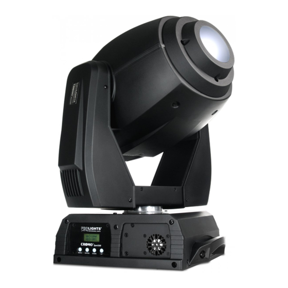
LED più potenti della sua categoria, concepito per sostituire i tradizionali proiettori con lampada a scarica MSR/HMI 575W. CROMOSPOT500 è equipaggiato con un ampio set di effetti e funzioni, costituito da 7 filtri di colore dicroici, 2 ruote gobos di cui una rotante (6 gobos) e l’altra fissa (7 gobos), prisma a tre facce, iris e focus motorizzato. - Page 9 CROMOSPOT500 Struttura e corpo mobile: • Corpo: in polimeri ignifughi ad alta resistenza, colore nero. • Maniglie ergonomiche laterali per il trasporto. • Escursione: Pan= 540° Tilt= 270°. • Risoluzione Pan/Tilt: 8-bit o 16-bit: • Pan = 2,10° Pan Fine = 0,008° Tilt = 1,05° Tilt Fine = 0,004°.
-
Page 10: Installazione
- 2 - INSTALLAZIONE 2.1 MONTAGGIO Il CROMOSPOT500 può essere collocato su un piano solido. Inoltre, grazie ai fori di fissaggio, l’unità può essere montata anche a testa in giù, su una traversa (fig.4). Per il fissaggio occorrono dei supporti robusti per il montaggio. -
Page 11: Funzioni E Impostazioni
“reset”. Poco dopo l’unità è pronta. Dopo l’uso spegnere l’unità attraverso il medesimo l’interruttore. 3.2 IMPOSTAZIONE BASE Il proiettore CROMOSPOT500 dispone di un display LCD e di 4 pulsanti per l’accesso alle funzioni del pan- nello di controllo e la loro gestione (fig.5). Welcome... -
Page 12: Struttura Del Menu
CROMOSPOT500 3.3 STRUTTURA DEL MENU Address 001-512 Reset Dmx512 Auto1 Auto2 Custom Sound1 Sound2 Slave Intro Test Basic Person Advanced 60 Close Display Bright Keylock Dimmer4 Dimmer3 Dimmer Dimmer2 Dimmer1 Dimmer0 MENU Info Edition Normal Reverse Normal Tilt Reverse Invert... -
Page 13: Funzionamento In Modalità Stand-Alone
• Selezionare la modalità di funzionamento desiderata fra [Auto1], [Auto2], [Custom], [Sound1], [Sound2], [Slave] o [Test], e premere il tasto ENTER. L’unità entrerà nella modalità scelta mandando in esecuzione il pro- gramma desiderato. NOTA. Nella modalità stand-alone il CROMOSPOT500 è impostato come unità principale (Master). -
Page 14: Collegamento
• Sull’unità master selezionare il programma desiderato come indicato nel paragrafo 3.4. • Servirsi dei connettori DMX del CROMOSPOT500 e di un cavo XLR per formare una catena di unità. In certe condizioni e lunghezze si consiglia di effettuare una terminazione come mostrato a pagina 15. -
Page 15: Costruzione Del Terminatore Dmx
CROMOSPOT500 DMX - INPUT DMX - OUTPUT Spina XLR Presa XLR Pin1 : Massa - Schermo Pin2 : - Negativo Pin3 : + Positivo Pin4 : N/C Pin5 : N/C ATTENZIONE La parte schermata del cavo (calza) non deve mai essere collegata alla terra dell’impianto; ciò comportereb- be malfunzionamenti delle unità... -
Page 16: Impostazione Dell'indirizzo Di Start
DMX per il primo canale DMX. Se, per esempio, sull’unità di comando è previsto l’indirizzo 33 per comanda- re la funzione del primo canale DMX, si deve impostare sul CROMOSPOT500 l’indirizzo di start 33. Le altre funzioni del pannello saranno assegnate automaticamente agli indirizzi successivi. Segue un esempio con... - Page 17 CROMOSPOT500 Channel Function in ADVANCED mode Channel Function in ADVANCED mode value value GOBO WHEEL1 IRIS No Gobo 000-010 Linear Iris 000-199 Gobo 1 011-020 Iris effect: fast close & slow Gobo 2 021-030 open (slow to fast) 200-209 Gobo 3 031-040 Iris effect: slow close &...
- Page 18 CROMOSPOT500 Channel Function in BASIC mode Channel Function in BASIC mode value value Shaking gobo 3 116-130 000-255 Shaking gobo 2 131-145 0 - 540° Shaking gobo 1 146-160 TILT Flow effect 161-255 000-255 0-270° GOBO WHEEL 2 ROTATION COLOR WHEEL 360°...
- Page 19 CROMOSPOT500 Channel Function in BASIC mode value Iris effect: slow close & fast 220-229 open (slow to fast) Iris effect: fast close & fast open 230-239 (slow to fast) 240-255 Iris effect: Random (slow to fast) FOCUS 000-255 Far - Near...
-
Page 20: Programmazione Personalizzata
• Scegliere il valore desiderato per il parametro servendosi dei tasti UP e DOWN e confermare l’imposta- zione premendo il tasto ENTER. Il CROMOSPOT500 eseguirà tutti gli “step” nella modalità [Custom] (vedi paragrafo 3.4 Funzionamento in mo- dalità Stand-alone) e poi si fermerà. Qualora si voglia effettuare un ciclo continuo è necessario aggiungere un ultimo passo (step), la cui durata deve essere pari a 0 secondi. - Page 21 CROMOSPOT500 Funzione Range • Premere il tasto MENU fino a quando sul display non appare [Range], quindi premere il tasto ENTER per confermare la scelta. • Con i tasti UP e DOWN selezionare il parametro che si desidera modificare fra [P/start], [P/finish], [T/start], [T/finish] e premere ENTER.
- Page 22 CROMOSPOT500 Impostazioni Display • Premere il tasto MENU fino a quando sul display non appare [Intro], quindi premere il tasto ENTER per confermare la scelta. • Premere i tasti UP e DOWN per selezionare nel menu la voce [Display] e confermare la scelta premendo il tasto ENTER.
-
Page 23: Manutenzione
CROMOSPOT500 - 4 - MANUTENZIONE 4.1 PULIZIA SISTEMA OTTICO E MANUTENZIONE • Durante gli interventi, assicurarsi che l’area sotto il luogo di installazione sia libera da personale non qualificato. • Spegnere l’unità, scollegare il cavo di alimentazione ed aspettare finché l’unità non si sia raffreddata. -
Page 24: Sostituzione Gobos
CROMOSPOT500 4.3 SOSTITUZIONE GOBOS I gobos rotanti, nella ruota, possono essere cambiati e sostituiti, per esempio, con propri gobos: 1. Staccare la spina dalla presa di rete. 2. Svitare le viti per togliere la coperture della testa mobile. 3. Girare la ruota, come indicato nella figura 7, in modo che il gobo da sostituire si trovi in alto. -
Page 25: Sostituzione Fusibile
CROMOSPOT500 4.4 SOSTITUZIONE FUSIBILE 1. Assicurarsi di scollegare il cavo di alimentazione del proiettore prima di sostituire un fusibile bruciato con uno dello stesso tipo e valore. 2. Con un cacciavite, rimuovere il portafusibile dalla sua sede e il fusibile bruciato dal suo supporto; sosti- tuire il fusibile con uno identico per tipologia e valore. -
Page 26: Appendice
CROMOSPOT500 - 5 - APPENDICE 5.1 VISTA ESPLOSA ITEM ITEM ITEM Head front cover Rotation wheel supports Display PCB Lenses Lenses supports Base cover Prism Head structure Power supply Motor Handle LED PCB Plastic arm Base Head cover Y axes drive team... - Page 29 4. 4 Fuse replacement 5 Appendix 5. 1 Exploded view Warranty PACKING CONTENT: • CROMOSPOT500 • Safety cable • Omega kit (2 pc.) • User manual All rights reserved by Music & Lights S.r.l. No part of this instruction manual may be.
-
Page 30: General Instructions
CROMOSPOT500 WARNING! Before carrying out any operations with the unit, carefully read this instruction manual and keep it with cure for future reference. It contains important information about the installation, usage and maintenance of the unit. SAFETY General instructions • The products referred to in this manual conform to the European Community Directives and are therefore marked with . -
Page 31: General Information
CROMOSPOT500 GENERAL INFORMATION Shipments and claims The goods are sold “ex works” and always travel at the risk and danger of the distributor. Eventual damage will have to be claimed to the freight forwarder. Any claim for broken packs will have to be forwarded within 8 days from the reception of the goods. -
Page 32: Description And Technical Specifications
CROMOSPOT500 - 1 - DESCRIPTION AND TECHNICAL SPECIFICATIONS 1.1 OPERATING ELEMENTS AND CONNECTIONS Fig.1 9 10 4 5 6 7 A view B view... - Page 33 CROMOSPOT500 1. MOVING HEAD 9. DMX IN (5-pole XLR): 2. ROTARY ARM 1 = ground, 2 = DMX -, 3 = DMX +, 4 N/C, 5 N/C. 3. LCD DISPLAY 10. DMX IN (3-pole XLR): 4. MENU button: exits from the current menu or 1 = ground, 2 = DMX-, 3 = DMX+.
-
Page 34: Description
MSR/ HMI 575W lamp. CROMOSPOT500 features a wide range of functions and effects, composed by 7 dichroic colour filters, 2 gobo wheels, one rotating (6 gobos) and one static (7 gobos), 3-facet prism, electronic iris and focus for limitless effect combinations. - Page 35 CROMOSPOT500 Structure and moving body • High resistance and flame retardant polymer case in black colour. • Ergonomic side handles for transportation. • Motion Angle: Pan = 540° Tilt = 270°. • Pan/Tilt resolution: 8-bit or 16-bit. • Pan = 2,10° Pan Fine = 0,008° Tilt = 1,05° Tilt Fine = 0,004°.
-
Page 36: Installation
2.1 MOUNTING The CROMOSPOT500 may be set up on a solid and even surface. By means of the fixing facilities of the base plate, the unit can also be mounted upside down to a cross arm. The base plate is shown in fig.4. For fixing, stable mounting clips are required. -
Page 37: Functions And Settings
(6) . Shortly after that the CROMOSPOT500 is ready for operation. After operation, switch off the unit with the power switch. 3.2 BASIC The CROMOSPOT500 has a LCD display and 4 button used to access the control panel functions and man- age them (fig.5). Welcome... -
Page 38: Menu Structure
CROMOSPOT500 3.3 MENU STRUCTURE Address 001-512 Reset Dmx512 Auto1 Auto2 Custom Sound1 Sound2 Slave Intro Test Basic Person Advanced 60 Close Display Bright Keylock Dimmer4 Dimmer3 Dimmer Dimmer2 Dimmer1 Dimmer0 MENU Info Edition Normal Reverse Normal Tilt Reverse Invert Normal... -
Page 39: Operation In Stand-Alone Mode
CROMOSPOT500 Blackdelay Reset System Special Fanwait Save DMXerror Black Step (001-255) (000-255) Tilt (000-255) Speed (000-255) Color (000-255) Gobo1 (000-255) MENU Gobo2 (000-255) Gobo2rot (000-255) Edit Prism (000-255) Prismt (000-255) Iris (000-255) Focus (000-255) Dimmer (000-255) Strobe (000-255) Time (000-255) -
Page 40: Linking
• Press the UP and DOWN buttons to select [Channels] menu voice and confirm the choice by pressing the ENTER button. • Select a DMX configuration: [Basic] or [Adavnced], and press ENTER button. The tables on page 12 indicate the operating mode and DMX value. The CROMOSPOT500 is equipped with 3-5 pole XLR connections. 3.8 DMX MODE • Press the MENU button and select, via the directional buttons, the [Intro] menu choice, then press the... -
Page 41: Construction Of The Dmx Termination
CROMOSPOT500 DMX - INPUT DMX - OUTPUT XLR plug XLR socket Pin1 : Ground Pin2 : - Negative Pin3 : + Positive Pin4 : N/C Pin5 : N/C ATTENTION The screened parts of the cable (sleeve) must never be connected to the system’s earth, as this would cause faulty fixture and controller operation. -
Page 42: Adjusting The Start Address
3.11 ADJUSTING THE START ADDRESS To able to operate the CROMOSPOT500 with a light controller, adjust the DMX start address for the first a DMX channel. If e. g. address 33 on the controller is provided for controlling the function of the first DMX channel, adjust the start address 33 on the CROMOSPOT500. - Page 43 CROMOSPOT500 Channel Function in ADVANCED mode Channel Function in ADVANCED mode value value GOBO WHEEL1 IRIS No Gobo 000-010 Linear Iris 000-199 Gobo 1 011-020 Iris effect: fast close & slow Gobo 2 021-030 open (slow to fast) 200-209 Gobo 3 031-040 Iris effect: slow close &...
- Page 44 CROMOSPOT500 Channel Function in BASIC mode Channel Function in BASIC mode value value Shaking gobo 3 116-130 000-255 Shaking gobo 2 131-145 0 - 540° Shaking gobo 1 146-160 TILT Flow effect 161-255 000-255 0-270° GOBO WHEEL 2 ROTATION COLOR WHEEL 360°...
- Page 45 CROMOSPOT500 Channel Function in BASIC mode value Iris effect: slow close & fast 220-229 open (slow to fast) Iris effect: fast close & fast open 230-239 (slow to fast) 240-255 Iris effect: Random (slow to fast) FOCUS 000-255 Far - Near...
-
Page 46: Edit Custom
• Enter [Use] and select [Yes] to run the steps user need. CROMOSPOT500 will execute all the steps in the custom program and it will stop. To make the fixture to start over add a last step whose duration is 0 second. - Page 47 CROMOSPOT500 Range function • Press the MENU button, select the [Range] menu voice and press the ENTER button to confirm the choice. • Select the parameter to be changed between [P/start], [P/finish], [T/start] and [T/finish]; press the ENTER button to confirm.
- Page 48 CROMOSPOT500 Display setting • Press the MENU button and select, via the directional buttons, the [Intro] menu choice, then press the ENTER button to confirm the choice. • Press the UP and DOWN buttons to select [Display] menu voice and confirm the choice by pressing the ENTER button.
-
Page 49: Maintenance
CROMOSPOT500 - 4 - MAINTENANCE 4.1 CLEANING THE UNIT AND MAINTENANCE • Make sure the area below the installation place is free from unwanted persons during setup. • Switch off the unit, unplug the main cable and wait until the unit has cooled down. -
Page 50: Replacement Of The Gobos
CROMOSPOT500 4.3 REPLACEMENT OF THE GOBOS The rotating gobos can be replaced and e. g. be exchanged for individual gobos. 1. Disconnect the main plug from the socket. 2. Release the screws and remove the part of the pan head. -
Page 51: Fuse Replacement
CROMOSPOT500 4.4 FUSE REPLACEMENT 1. With a flat head screwdriver, wedge the fuse holder out of its housing and remove the blown fuse from its holder. 2. Replace the blown fuse with a fuse of the exact same type and rating. -
Page 52: Appendix 5. 1 Exploded View
CROMOSPOT500 - 5 - APPENDIX 5.1 EXPLODED VIEW ITEM ITEM ITEM Head front cover Rotation wheel supports Display PCB Lenses Lenses supports Base cover Prism Head structure Power supply Motor Handle LED PCB Plastic arm Base Head cover Y axes drive team... - Page 53 Place Stamp Here Affrancare Spett.le Music&Lights S.r.l. Via Appia Km 136.200 04020 Itri (LT) Italy "...
- Page 56 Music & Lights S.r.l. entertainment technologies Via Appia Km 136,200 - 04020 Itri (LT) ITALY ISO 9001:2008 tel. +39 0771 72190 fax +39 0771 721955 Certified Company www.musiclights.it info@musiclights.it...
Need help?
Do you have a question about the CROMOSPOT500 and is the answer not in the manual?
Questions and answers