Table of Contents
Advertisement
Available languages
Available languages
Quick Links
Advertisement
Chapters
Table of Contents

Subscribe to Our Youtube Channel
Related Manuals for ProLights CROMOSPOT400


Summary of Contents for ProLights CROMOSPOT400
- Page 1 CROMOSPOT400 MOVING HEAD Manuale Utente User Manual...
- Page 2 Music & Lights S.r.l. si riserva ogni diritto di elaborazione in qualsiasi forma delle presenti istruzioni per l’uso. La riproduzione - anche parziale - per propri scopi commerciali è vietata. Al fine di migliorare la qualità dei prodotti, la Music&Lights S.r.l. si riserva la facoltà di modificare, in qualunque momento e senza preavviso, le specifiche menzionate nel presente manuale di istruzioni.
-
Page 3: Table Of Contents
4. 1 Manutenzione e pulizia sistema ottico 4. 2 Sostituzione fusibile 4. 3 Sostituzione gobos 4. 4 Risoluzione dei problemi 5 Appendice 5. 1 Vista esplosa Certificato di garanzia Contenuto dell'imballo: • CROMOSPOT400 • Cavo di sicurezza • Supporti omega (2pz.) • Manuale utente... -
Page 4: Sicurezza
CROMOSPOT400 ATTENZIONE! Prima di effettuare qualsiasi operazione con l’unità, leggere con attenzione questo manuale e conservarlo accuratamente per riferimenti futuri. Contiene informazioni importanti riguardo l’installazione, l’uso e la manutenzione dell’unità. SICUREZZA Avvertenze generali • I prodotti a cui questo manuale si riferisce sono conformi alle Direttive della Comunità Europea e per- tanto recano la sigla . -
Page 5: Informazioni Generali
CROMOSPOT400 INFORMAZIONI GENERALI Spedizioni e reclami Le merci sono vendute “franco nostra sede” e viaggiano sempre a rischio e pericolo del distributore/clien- te. Eventuali avarie e danni dovranno essere contestati al vettore. Ogni reclamo per imballi manomessi dovrà essere inoltrato entro 8 giorni dal ricevimento della merce. -
Page 6: Descrizione
CROMOSPOT400 - 1 - DESCRIZIONE 1.1 SPECIFICHE TECNICHE Sorgente luminosa e ottica • Sistema di lenti e obbiettivo ottico brevettati per garantire un’ efficienza luminosa di gran lunga supe- riore a proiettori della medesima categoria di potenza • 7 x 10W (3A) LED bianco ad alta resa luminosa • Lumens: 2800 lm... - Page 7 CROMOSPOT400 • Pan = 2,10° Pan Fine = 0,008° Tilt = 1,05° Tilt Fine = 0,004° • Riposizionamento automatico degli effetti in seguito a spostamenti accidentali • Sospensione e fissaggio: qualsiasi posizione per mezzo di supporti omega (inclusi) Alimentazione • Alimentazione: 100-240V 50/60Hz • Consumo ad emissione massima: 160 W...
-
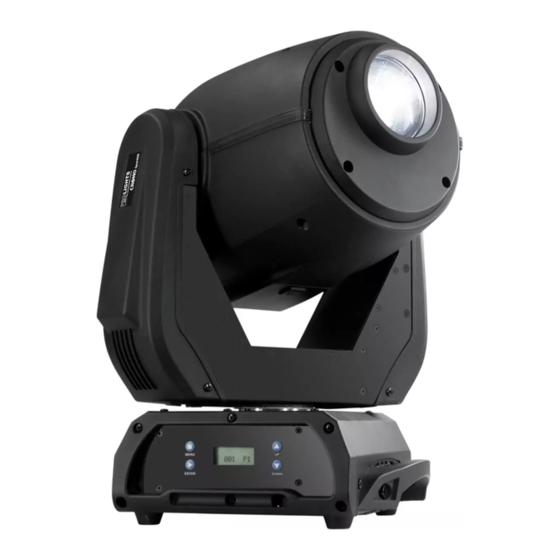
Page 8: Elementi Di Comando E Di Collegamento
CROMOSPOT400 1.2 ELEMENTI DI COMANDO E DI COLLEGAMENTO Fig.1 Vista A Vista B... - Page 9 CROMOSPOT400 1. TESTA MOBILE 5. PORTAFUSIBILE sostituire un fusibile difettoso 2. BRACCIO GIREVOLE solo con uno delle stesso tipo 3. MANIGLIA per trasporto 6. INTERRUTTORE ON/OFF 4. PANNELLO DI CONTROLLO con display LCD e 7. DMX IN (XLR a 5 poli):...
-
Page 10: Installazione
- 2 - INSTALLAZIONE 2.1 MONTAGGIO Il CROMOSPOT400 può essere collocato su un piano solido. Inoltre, grazie ai fori di fissaggio, l’unità può essere montata anche a testa in giù, su una traversa (fig.2). Per il fissaggio occorrono dei supporti robusti per il montaggio. -
Page 11: Funzioni E Impostazioni
Poco dopo l’unità è pronta. Dopo l’uso spegnere l’unità attraverso il medesimo l’interruttore. 3.2 IMPOSTAZIONE BASE Il proiettore CROMOSPOT400 dispone di un display LCD e di 4 pulsanti per l’accesso alle funzioni del pan- nello di controllo e la loro gestione (fig.3). Fig.3... -
Page 12: Struttura Menu
CROMOSPOT400 3.3 STRUTTURA MENU ADDRESS 001 - 512 PERSON1 PERSON PERSON2 FAST PT SPEED SLOW NORM PAN INV INVERT NORM TILT INV INVERT FAST OP SPEED SLOW INSTANT BLACK DELAY DIM4 DIM3 DIMMER DIM2 DIM1 PERFORM NORM DIM INV INVERT... - Page 13 CROMOSPOT400 DMX512 AUTO1 AUTO2 SOUND1 SOUND2 CUSTOM TEST SLAVE STEP 001 - 049 000 - 255 TILT 000 - 255 COLOR 000 - 255 RUNMODE GOBO1 000 - 255 GOBO2 000 - 255 GOBO2ROT 000 - 255 EDIT PRI&ROT 000 - 255...
-
Page 14: Funzionamento In Modalità Automatica
• Infine, entrare nella modalità [USE] e selezionare [YES] per rendere attive le nuove impostazioni. Il CROMOSPOT400 eseguirà tutti gli “step” nella modalità [CUSTOM] (vedi paragrafo 3.4 “Funzionamento in modalità automatica”) e poi si fermerà. Qualora si voglia effettuare un ciclo continuo è necessario aggiun- gere un ultimo passo (step), la cui durata deve essere pari a 0 secondi. -
Page 15: Modalità Master/Slave
• Sull’unità master selezionare il programma desiderato come indicato al paragrafo 3.4. • Servirsi dei connettori DMX del CROMOSPOT400 e di un cavo XLR per formare una catena di unità. In certe condizioni e lunghezze si consiglia di effettuare una terminazione come mostrato a pagina 17. - Page 16 DMX per il primo canale DMX. Se, per esempio, sull’unità di comando è previsto l’indirizzo 33 per comandare la funzione del primo canale DMX, si deve impostare sul CROMOSPOT400 l’indirizzo di start 33. Le altre funzioni del pannello saranno assegnate automaticamente agli indirizzi successivi.
-
Page 17: Collegamenti Della Linea Dmx
CROMOSPOT400 3.11 COLLEGAMENTI DELLA LINEA DMX La connessione DMX è realizzata con connettori standard XLR. Utilizzare cavi schermati, 2 poli ritorti, con impedenza 120Ω e bassa capacità. Per il collegamento fare riferimento allo schema di connessione riportato di seguito: DMX - INPUT... -
Page 18: Tabella Canali Dmx
CROMOSPOT400 3.13 TABELLA CANALI DMX PERSON1 CH Function in PERSON1 Value CH Function in PERSON1 Value Shaking gobo 6 096 - 110 0 - 540° 000 - 255 Shaking gobo 5 111 - 125 Shaking gobo 4 126 - 140... - Page 19 CROMOSPOT400 CH Function in PERSON1 Value STROBE Close 000 - 031 Open 032 - 063 Strobe: Slow --> Fast 064 - 095 Open 096 - 127 Pulse strobe effect: Slow --> Fast 128 - 159 Open 160 - 191 Random strobe effect: Slow --> Fast...
- Page 20 CROMOSPOT400 PERSON2 CH Function in PERSON2 Value CH Function in PERSON2 Value Shaking gobo 3 141 - 155 Shaking gobo 2 156 - 170 0 - 540° 000 - 255 Shaking gobo 1 171 - 185 PAN FINE Flow effect 186 - 255 0 - 270°...
- Page 21 CROMOSPOT400 CH Function in PERSON2 Value STROBE Close 000 - 031 Open 032 - 063 Strobe: Slow --> Fast 064 - 095 Open 096 - 127 Pulse strobe effect: Slow --> Fast 128 - 159 Open 160 - 191 CONTROL...
-
Page 22: Impostazioni Del Proiettore
CROMOSPOT400 3.14 IMPOSTAZIONI DEL PROIETTORE Per il CROMOSPOT400 è possibile modificare i parametri relativi al dispositivo: Impostazione funzioni proiettore 1. Dal menu iniziale, premere il tasto MENU fino a quando sul display non appare [SETTINGS], quindi premere il tasto ENTER. -
Page 23: Modalità Manuale
• Premere il tasto MENU per tornare indietro o attendere qualche secondo per uscire dal menu di impostazione. 3.15 MODALITÀ MANUALE Per il CROMOSPOT400 è possibile effettuare le seguenti regolazioni di funzioni: Reset • Dal menu iniziale, premere il tasto MENU fino a quando sul display non appare [MANUAL], quindi premere il tasto ENTER. -
Page 24: Impostazioni Service
CROMOSPOT400 3.16 IMPOSTAZIONI SERVICE Per controllare l'accesso alle impostazioni del proiettore è possibile far riferimento alle seguenti funzioni: Blocco delle impostazioni • Dal menu iniziale, premere il tasto MENU fino a quando sul display non appare [SERVICE], quindi premere il tasto ENTER. -
Page 25: Manutenzione
CROMOSPOT400 - 4 - MANUTENZIONE 4.1 MANUTENZIONE E PULIZIA DEL SISTEMA OTTICO • Durante gli interventi, assicurarsi che l’area sotto il luogo di installazione sia libera da personale non qualificato. • Spegnere l’unità, scollegare il cavo di alimentazione ed aspettare finché l’unità non si sia raffreddata. -
Page 26: Sostituzione Gobos
CROMOSPOT400 4.3 SOSTITUZIONE GOBOS I gobos rotanti, nella ruota, possono essere cambiati e sostituiti, per esempio, con propri gobos: 1. Staccare la spina dalla presa di rete. 2. Rimuovere le coperture per accedere alla ruota gobos. 3. Girare la ruota, come indicato nella figura 8, in modo che il gobo da sostituire si trovi in alto. -
Page 27: Risoluzione Dei Problemi
CROMOSPOT400 4.4 RISOLUZIONE DEI PROBLEMI Anomalie Possibili cause Controlli e rimedi Mancanza di alimentazione di rete Verificare la presenza della tensione alimentazione • • Dimmer impostato a 0 Incrementare i valori del canale dimmer • • Tutti i colori impostati a 0... -
Page 28: Appendice
CROMOSPOT400 - 5 - APPENDICE 5.1 VISTA ESPLOSA Fig.11 No ITEM No ITEM No ITEM No ITEM 1 Head plastic front cover LED board Base box cover (PS) U-frame side plate 1 2 Ø 80 agglutination lens Heat sink Handgrip... - Page 30 All rights reserved by Music & Lights S.r.l. No part of this instruction manual may be reproduced in any form or by any means for any commercial use. In order to improve the quality of products, Music&Lights S.r.l. reserves the right to modify the characteristics stated in this instruction manual at any time and without prior notice.
-
Page 31: Cromospot400
4. 1 Maintenance and cleaning the unit 4. 2 Fuse replacement 4. 3 Replacement of the gobos 4. 4 Trouble shooting 5 Appendix 5. 1 Exploded view Warranty Packing content • CROMOSPOT400 • Safety cable • Mount bracket (2pc.) • User manual... -
Page 32: General Instructions
CROMOSPOT400 WARNING! Before carrying out any operations with the unit, carefully read this instruction manual and keep it with cure for future reference. It contains important information about the installation, usage and maintenance of the unit. SAFETY General instruction • The products referred to in this manual conform to the European Community Directives and are there- fore marked with . -
Page 33: General Information
CROMOSPOT400 GENERAL INFORMATION Shipments and claims The goods are sold “ex works” and always travel at the risk and danger of the distributor. Eventual dam- age will have to be claimed to the freight forwarder. Any claim for broken packs will have to be forwarded within 8 days from the reception of the goods. -
Page 34: Description
CROMOSPOT400 - 1 - DESCRIPTION 1.1 TECHNICAL SPECIFICATIONS Light source and optics • Patented optical and lens path for superior output • 7 x 10W (3A) high-power white LED • Lumens: 2800 lm • Brightness: 11000 Lux @2mt • Projection angle: 16°... - Page 35 CROMOSPOT400 Power supply • Power unit: 100-240V 50/60Hz • Max power consumption: 160 W • Power connection: Powercon IN/OU Weight and dimensions • Weight: 12,5 kg • Dimensions (WxHxD): 330x270x473 mm...
-
Page 36: Operating Elements And Connections
CROMOSPOT400 1.2 OPERATING ELEMENTS AND CONNECTIONS Fig.1 View A View B... - Page 37 CROMOSPOT400 1. MOVING HEAD 5. FUSE OLDER in the event of breakage, always 2. ROTARY ARM replace the fuse with the same type and 3. ERGONOMIC HANDLES for carrying and rating. positioning. 6. ON/OFF SWITCH 4. CONTROL PANEL with display and 4 button 7.
-
Page 38: Installation
2.1 MOUNTING The CROMOSPOT400 may be set up on a solid and even surface. By means of the fixing facilities of the baseplate, the unit can also be mounted upside down to a cross arm. The base plate is shown in fig.2. -
Page 39: Functions And Settings
CROMOSPOT400 is ready for operation. After operation, switch off the unit with the power switch. 3.2 BASIC The CROMOSPOT400 has a LCD display and 4 button used to access the control panel functions and man- age them (fig.3). Fig.3... -
Page 40: Menu Structure
CROMOSPOT400 3.3 MENU STRUCTURE ADDRESS 001 - 512 PERSON1 PERSON PERSON2 FAST PT SPEED SLOW NORM PAN INV INVERT NORM TILT INV INVERT FAST OP SPEED SLOW INSTANT BLACK DELAY DIM4 DIM3 DIMMER DIM2 DIM1 PERFORM NORM DIM INV INVERT... - Page 41 CROMOSPOT400 DMX512 AUTO1 AUTO2 SOUND1 SOUND2 CUSTOM TEST SLAVE STEP 001 - 049 000 - 255 TILT 000 - 255 COLOR 000 - 255 RUNMODE GOBO1 000 - 255 GOBO2 000 - 255 GOBO2ROT 000 - 255 EDIT PRI&ROT 000 - 255...
-
Page 42: Operation In Automatic Mode
• Enter [USE] and select [YES] to run the steps user need. CROMOSPOT400 will execute all the steps in the custom program and it will stop. To make the fixture to start over add a last step whose duration is 0 second. -
Page 43: Linking
• Press the MENU button to go back or wait some seconds for automatic exit from the menu. To able to operate the CROMOSPOT400 with a light controller, adjust the DMX start address for the first a DMX channel. If e. g. address 33 on the controller is provided for controlling the function of the first DMX channel, adjust the start address 33 on the CROMOSPOT400. -
Page 44: Connection Of The Dmx Line
CROMOSPOT400 DMX Address: 33 DMX Address: 47 DMX Address: 61 DMX Address: 75 ... . DMX512 Controller Example 14 DMX channels configuration (PERSON1 mode) Fig.4 3.11 CONNECTION OF THE DMX LINE DMX connection employs standard XLR connectors. -
Page 45: Construction Of The Dmx Termination
CROMOSPOT400 3.12 CONSTRUCTION OF THE DMX TERMINATION The termination avoids the risk of DMX 512 signals being reflected back along the cable when they reach- es the end of the line: under certain conditions and with certain cable lengths, this could cause them to cancel the original signals. -
Page 46: Dmx Control
CROMOSPOT400 3.13 DMX CONTROL PERSON1 CH Function in PERSON1 Value CH Function in PERSON1 Value Shaking gobo 6 096 - 110 0 - 540° 000 - 255 Shaking gobo 5 111 - 125 Shaking gobo 4 126 - 140 PAN FINE... - Page 47 CROMOSPOT400 CH Function in PERSON1 Value STROBE Close 000 - 031 Open 032 - 063 Strobe: Slow --> Fast 064 - 095 Open 096 - 127 Pulse strobe effect: Slow --> Fast 128 - 159 Open 160 - 191 Random strobe effect: Slow --> Fast...
- Page 48 CROMOSPOT400 PERSON2 CH Function in PERSON2 Value CH Function in PERSON2 Value Shaking gobo 3 141 - 155 Shaking gobo 2 156 - 170 0 - 540° 000 - 255 Shaking gobo 1 171 - 185 PAN FINE Flow effect 186 - 255 0 - 270°...
- Page 49 CROMOSPOT400 CH Function in PERSON2 Value STROBE Close 000 - 031 Open 032 - 063 Strobe: Slow --> Fast 064 - 095 Open 096 - 127 Pulse strobe effect: Slow --> Fast 128 - 159 Open 160 - 191 CONTROL...
-
Page 50: Fixture Settings
CROMOSPOT400 3.14 FIXTURE SETTINGS It is possible to change the parameter value in the following way: Settings functions 1. Press the button MENU so many times until the display shows [SETTINGS], then press the button ENTER. 2. Press the button UP/DOWN to select [PERFORM], press ENTER button to confirm the choice. -
Page 51: Manual Mode
CROMOSPOT400 Reset function • Press the button MENU so many times until the display shows [SETTINGS], then press the button ENTER. • Press the button UP/DOWN to select [DEFAULT], press ENTER button to confirm the choice. • Select [YES] in order to reset the default values. -
Page 52: Fixture Information
CROMOSPOT400 • Press UP/DOWN button to select [SERVICE LOCK] and press ENTER button. • Select [ON] or [OFF] through the buttons UP/DOWN to enable access to service menu. To edit the text that appears on the display in standby mode to refer to the following functions: Display1 • Press the button MENU so many times until the display shows [SERVICE], then press the button ENTER. -
Page 53: Maintenance
CROMOSPOT400 - 4 - MAINTENANCE 4.1 MAINTENANCE AND CLEANING THE UNIT • Make sure the area below the installation place is free from unwanted persons during setup. • Switch off the unit, unplug the main cable and wait until the unit has cooled down. -
Page 54: Replacement Of The Gobos
CROMOSPOT400 4.3 REPLACEMENT OF THE GOBOS The rotating gobos can be replaced and e. g. be exchanged for individual gobos. 1. Disconnect the main plug from the socket. 2. Remove the part of the pan head. 3. Turn the gobo wheel as indicated in fig.8 in such a way that the gobo to be replaced is on top. -
Page 55: Troubleshooting
CROMOSPOT400 4.4 TROUBLESHOOTING Problems Possible causes Checks and remedies No mains supply Check the power supply voltage • • Dimmer fader set to 0 Increase the value of the dimmer channels • • All color faders set to 0 Increase the value of the color channels •... -
Page 56: Appendix 5. 1 Exploded View
CROMOSPOT400 - 5 - APPENDIX 5.1 EXPLODED VIEW No ITEM No ITEM No ITEM No ITEM 1 Head plastic front cover LED board Base box cover (PS) U-frame side plate 1 2 Ø 80 agglutination lens Heat sink Handgrip Drive belf... - Page 57 Place Stamp Here Affrancare Spett.le Music&Lights S.r.l. Via Appia Km 136.200 04020 Itri (LT) Italy "...
- Page 60 Music & Lights S.r.l. entertainment technologies Via Appia km 136,200 - 04020 Itri (LT) ITALY ISO 9001:2008 tel. +39 0771 72190 fax +39 0771 721955 Certified Company www.musiclights.it info@musiclights.it...
Need help?
Do you have a question about the CROMOSPOT400 and is the answer not in the manual?
Questions and answers