HITEC ECLIPSE 7 Owner's Manual
For aircraft, gliders,
helicopters
Hide thumbs
Also See for ECLIPSE 7:
- System instruction manual (48 pages) ,
- Quick start manual (7 pages)

Related Manuals for HITEC ECLIPSE 7


Summary of Contents for HITEC ECLIPSE 7
- Page 1 ® Hitec ECLIPSE 7 Owner’s Manual SYSTEM INSTRUCTION MANUAL FOR AIRCRAFT • GLIDERS • HELICOPTERS 7 CHANNELS • 7 MEMORIES • PROGRAMMABLE FM SHIFT – 1 –...
-
Page 2: Introduction To The Eclipse 7 System
Congratulations! You now own a its menus!! ® Eclipse 7 , an extremely versatile R/C Hitec The extensive preprogrammed mixing system that may be effectively used by both features for aircraft include flaperon (dual beginning and master pilots. - Page 3 as helpful to you, the new owner, as possible. There are many pages of setup procedures, examples, explanations, trimming instructions. In order for you to make the best use of your system and to fly safely, please read this manual carefully. If you don’t have time to read it thoroughly, at least spend some time browsing through it to see all the features this fine system has to offer.
-
Page 4: Eclipse 7 System Options
Hitec is not responsible for the results of Eclipse 7 System Options: use of this product by the customer or for any 1. Airplane Version, Item #171721. alteration of this product, including Includes four HS-422 deluxe servos, 8 modification or incorporation into other channel Supreme receiver, 600 mAH devices by third parties. -
Page 5: Table Of Contents
Vibration and VTAL — V-Tail Mixing.......... Waterproofing ..................11 FLPN — Flaperon Mixing........Charging the Eclipse 7 Ni-Cd Batteries ..............12 Aircraft Flight Trimming Chart......Operating With A Trainer Cord ................12 Glider (GLID) Menu Functions......Other Adjustments ....................13 Eclipse 7 Glider Controls and Switch Adjustable length control sticks .................. - Page 6 Menu Descriptions — Helicopter ................88 Flight Conditions........................ 88 → R->T — Rudder Throttle Mixing.................. 89 GYRO — Gyro settings....................... 90 HOLD — Throttle Hold ...................... 90 THCV — Throttle Curve ....................91 PTCV — Pitch Curve......................92 RVMX — Revolution mixing ....................93 SWAH —...
-
Page 7: Flying Safety
at the same time. Even though there are Flying Safety different types of modulation (AM, PPM or FM, and PCM), only one model may be flown To ensure your own safety and the safety of on a single frequency. others, please observe the following When you are ready to fly your model, precautions: position the throttle stick to its low speed... - Page 8 protect your transmitter with a plastic bag or waterproof barrier.
-
Page 9: Airplane Frequencies
25 72.290 50 72.790 Airplane Frequencies 26 72.310 51 72.810 The following frequencies and channel 27 72.330 52 72.830 numbers may be used for flying aircraft in the 28 72.350 53 72.850 U.S. (this information specific to North American versions of the Eclipse): 29 72.370 54 72.870 30 72.390... -
Page 10: Radio Installation Notes
Radio Installation Notes While you are installing the battery, receiver, and servos into your model’s fuselage, please pay attention to the following guidelines: Notes on Servos Mounting When you mount each servo, use the supplied rubber grommets and insert an eyelet up through the bottom. Be sure not to overtighten the screws. If any portion of the servo case directly contacts the fuselage or the servo rails, the rubber grommets will not be able to attenuate vibration, which can lead to mechanical wear and servo failure. -
Page 11: Connectors
Additional Hitec extension cords of varying lengths are available from your hobby dealer. -
Page 12: Charging The Eclipse 7 Ni-Cd Batteries
The instructor may override the beginning pilot at any time to bring the model back under safe control. For training, the transmitter may be connected ® to another Hitec FM system, as well as to any Futaba FM transmitter (if Hitec cord #58310 is used). -
Page 13: Other Adjustments
3. The Hitec cord is specifically marked at one end as the “master” the other end as “student”. Plug it accordingly into each transmitter, with power switched off. The trainer jack is on the back of the transmitter. Turn the connector until its notches line up and it fits without having to be forced. -
Page 14: Changing The Eclipse 7 Transmitter's Mode
If you wish to change the mode of the transmitter, say from Mode 2 to Mode 1, return the radio to Hitec for conversion. If you don’t know what this means, you don’t need to worry about Factory Service Repair Information Please read the warranty card supplied with your system, and return it so your system will be under warranty. - Page 15 If you have any questions regarding this product, please consult with Hitec’s service center. The address and telephone numbers of our service center is given below. Telephone inquiries are accepted from 8:00 AM to 4:30 PM weekdays (closed on holidays).
-
Page 16: Eclipse 7 Controls And Switch Assignments Mode Ii
Eclipse 7 “Mode 2” Controls and Switch Assignments Insert “Eclipse 7 Mode 2 Switch Configuration List” drawing here (PDF file). This figure shows the assignments for a Mode 2 system as supplied by the factory in North America. Note that some of the functions will not operate until activated in the mixing menus. - Page 17 Eclipse 7 “Mode 1” Controls and Switch Assignments Insert “Eclipse 7 Mode 1 Switch Configuration List” drawing here (PDF file). This figure shows the assignments for a Mode 1 system as supplied by the factory (not in North American versions). Note that some of the functions will not operate until activated in the mixing menus.
-
Page 18: Transmitter Input Buttons
Transmitter Input Buttons: Edit Cursor Data Down Left Right Increase Decrease Clear Display Timer Save Active/Inhibit Engine Lock The buttons are used for different things as follows: 1. The buttons allow you to move up and down within the model menus, Edit/Display Up &... - Page 19 The servo response varies with the selected function. Standard options are shown first. – 19 –...
-
Page 20: Transmitter Displays & Messages
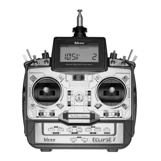
Transmitter Displays & Messages When you first turn on your transmitter, the first screen shown below appears on the LCD display. Before flying, or even starting the engine, BE SURE that the model number appearing in the lower right of the display matches the model that you are about to fly! If you don’t, reversed servos and incorrect trims will lead to an immediate crash. -
Page 21: Warning Displays
stored within by the memory number. MODEL 3 5 6 7 Pressing the button gives the Timer display, with a start/stop stopwatch display on the left, and operating time on the right. 9:56 This also starts the timer, so hit the key again to stop start/stop it. - Page 22 aft, then move the Flt. Cond. switch. For your safety, the transmitter will not broadcast until this alarm is ended. – –...
-
Page 23: Model Setup Functions
(ACRO) Aircraft Section Model Setup Functions This section describes the model setup functions that are used to choose all of the operating features of a particular model memory. These functions are used to select the model memory, the model type (from airplanes, gliders, and helicopters), set the stopwatch, and other useful functions. -
Page 24: Modl - Model Select
MODL — Model Select Your Eclipse 7 system can store up to seven independent sets of model data in its memory. The Model Select (MODL) function allows you to choose from any of the seven sets of model data. You can assign a four-character name to each model memory. -
Page 25: Acro, Heli, Glid - Model Type
(ACRO) Aircraft Section Current No. MODEL 5 6 7 Destination (flashing) COPY 3. The source model memory (the memory that will be duplicated) is the current one, indicated by the fixed upper arrow. To select your destination model number, press the Left Right keys. -
Page 26: Wing & Swashplate Type Selection
ERASE ALL THE OLD SETTINGS IN THE MODEL MEMORY, SO BE SURE YOU’RE IN THE CORRECT MODEL MEMORY BEFORE YOU CHANGE MODEL TYPE! 6. Press the arrow keys to get to another setup menu, or switch power off. Down 7. Switch power back on. You may now set up the details of your model in the Edit mode. Wing &... -
Page 27: Model Name
(ACRO) Aircraft Section If you're happy with the wing or swash type that is displayed, go on to the next step. If you wish to change the wing or swashplate type from that displayed, press on the Left Right Cursor buttons until the wing/swash type you want appears. -
Page 28: 2001 By Don Edberg
3. N represents negative shift and will work with Hitec and brand F. P represents positive shift and will work with brands A and J. The Eclipse 7 will not work with any PCM receivers. 4. To change the shift direction from what is shown, press either the... -
Page 29: Time -Timer Function Setup
(ACRO) Aircraft Section TIME- Timer Function Setup The timer function is helpful for keeping track of flight duration, engine run time, or other things that need to be monitored during flight. You can set up the timer to count down from anywhere from 0 to 60 minutes. -
Page 30: Aircraft (Acro) Menu Functions
2. Press the arrow key until you get into the Reset (REST) menu. This display has Up or Down the word “REST” flashing on and off. (If you’re already in the setup menus, you can just press the arrow key to get here.) Down MODEL 1 3 5 6 7... - Page 31 (ACRO) Aircraft Section ACRO Functions Map.......... (see right) Voltage/Timer Display Normal Display Mode Simple Aerobatic Airplane Transmitter Setup....32 Press both Edit/Display keys EPA....End Point Adjust (servo travels)......41 [ EPA] End Point Adjust D/R....Dual Rates............42 [ D /R] Dual Rate Set EXP....Exponential Settings.........43 [ EXP] Exponential...
-
Page 32: Simple Transmitter Setup - Aerobatic
(ACRO) Aircraft Section Simple Transmitter Setup — Aerobatic Airplane (ACRO) The following pages will take you step-by-step through the setup process for a sport or aerobatic airplane in the ACRO menu. Going through this complete section will help you learn how to use your system quickly and easily. If you need to set up a helicopter or glider, please refer to the quick setup instructions in the helicopter and glider sections. - Page 33 (ACRO) Aircraft Section 10. Press the arrow once. This gets you menu. Now we’ll set the servo throw FLPN into the Timer menu (TIME). If you want, you directions. can use the keys Data +Increase –Decrease Now check that each servo moves the proper to select the amount of time you want the direction.
- Page 34 (ACRO) Aircraft Section 19. Next we’ll set the direction of the elevator the right), the trailing edge or rear rudder servo, channel 2. When you move the right- should move to the right. Check to make sure! hand stick towards the BOTTOM of the RIGHT transmitter, the elevator should move up.
- Page 35 (ACRO) Aircraft Section 24. Before we set the servo neutrals, we need amount by adding or subtracting with the Data to be sure that all the trims are centered. Press keys. When you reach +Increase –Decrease both keys to get to the main menu, where a place where the right aileron matches up Edit voltage and time are displayed.
- Page 36 (ACRO) Aircraft Section 32. The Eclipse 7 provides a special throttle 37. To set the RIGHT aileron motion, move trim function which allows the throttle trim the aileron stick all the way to the right and lever to work at low throttle levels, but hold it.
- Page 37 –Decrease Data [Notice that the Eclipse 7 transmitter thinks of number is smaller. 50-75% is a good starting throttle stick positions to the reverse of the point. Watch to be sure you’re setting the way it seems, in that with the throttle stick down travel on the right aileron.
- Page 38 (ACRO) Aircraft Section 50. The aileron dual rate setting automatically above or below the numeral 4. Now set the affects both ailerons if the flaperon function is rudder dual rates in the same way you set the active. To set the aileron dual rate, move the ailerons and elevator in the previous steps.
- Page 39 CH. 7 switch, which turns mixer #1 on and off). This introduction just scratches the surface of the capabilities of your Eclipse 7 system. 67. Next, press the key once to Cursor Right Please read the manual so you’ll know what...
- Page 40 Section Eclipse 7 Aircraft Controls and Switch Assignments This should be the “Eclipse 7 Mode 2 Switch Configuration List” drawing with only the ACRO features listed (less confusing). This figure shows the assignments for a Mode 2 system as supplied by the factory for the North American version.
-
Page 41: Epa
(ACRO) Aircraft Section Airplane Model Function Descriptions — End Point Adjust function is used to set (or limit) the travel of each servo, and may be set anywhere from 0% and 125% for each travel direction. Reducing the percentage settings reduces the total servo throw in that direction. -
Page 42: D/R
(ACRO) Aircraft Section may set each channel separately, anywhere in between 0% and 125%, and if you wish to rapidly return to the default 100% setting, press the Active/Inhibit (Clear) key. 5. Return to the regular operating mode by pressing the two keys simultaneously. - Page 43 (like dual rates), and yet have full motion at full stick deflection. The Eclipse 7 allows you to have two different values of exponential, chosen by the same dual rate toggle switches on the transmitter, described earlier. You might want to set a dual rate at one switch position with zero exponential, and an exponential value with 100% dual rate at the other.
-
Page 44: Exp
Flight conditions are special functions which allow you to switch certain settings in the Eclipse 7 transmitter in order to tailor it to different conditions of flight. For example, you might have a scale model which is very sluggish at lower speeds (such as takeoff and landing) yet is very sensitive at higher speeds. - Page 45 Aircraft Section very unusual feature for a system in the class of the Eclipse 7 and they are normally found only on systems costing far more. As you learn to use them, you will really appreciate them. The priority of the conditions (when all three are activated) is as follows: ST3 > (ST1, ST2) >...
-
Page 46: Flt.c
(ACRO) Aircraft Section Flt. Mode Switch Flt. Cond Switch Active Flight Cond. Comments Any position Forward ST3 overrides all Forward Back ST2 active if ST3 off. LAND also on. Back Back ST1 active if ST3 off. (E->F on) Center Back Default condition Choosing Flight Conditions 1. -
Page 47: Strm
(ACRO) Aircraft Section 8. Again use the keys to get to the Expo menu, and set up a desired value of expo Edit Up Down for each flight condition. Again, you can only select one exponential value for each flight condition. -
Page 48: Rev
(ACRO) Aircraft Section mixers such as flaperon, be sure to set correct travels in the REV menu setting up the preprogrammed function. Reversing Servos 1. Get to the screen with the keys. Edit Up Down 2. Use the Data +Increase or –Decrease key to select the channel you wish to reverse. -
Page 49: Pmx1-5
(ACRO) Aircraft Section PMX1 to PMX5 — Programmable Mixes 1, 2, 3, 4, & 5 Your Eclipse 7 system contains FIVE separate programmable mixers ( — PMX1 PMX5 with unique capabilities. You may use mixing to correct unwanted tendencies of the aircraft during aerobatics. -
Page 50: Land
(ACRO) Aircraft Section • Now we'll input the mixing percentage, which tells how much the slave channel responds to the master channel. Press the key to cause the percent (%) sign to the right of Cursor Right the large number to flash on and off. Note that you can set the percentage for the mixer on each side of the master channel’s control’s motion by moving the master channel's control back and forth. -
Page 51: Flpt
(ACRO) Aircraft Section Setting up Landing function 1. Use the arrow keys to select the window. Depending on the position of Edit Up Down LAND the landing switch, the display will show a flashing OFF or ON. The Flt. Mode switch turns on LAND when all the way forward. - Page 52 (ACRO) Aircraft Section setting, press the key. You can toggle through the settings 0%, 30%, and Active/Inhibit (Clear) 100% by continuing to press this key. Setting it to 0% disables the flap knob, but the flaps will still respond to mixing functions such as E->F and to the Landing function. E->F —...
-
Page 53: A->R
(ACRO) Aircraft Section tries to yaw against the turn. Adding rudder mixing cures this problem by making the fuselage point straight into the oncoming air stream (this is also called “coordinating the turn”). The slower the model flies, the more mixing is needed, and the faster it moves, the less is needed. -
Page 54: Elvn
(ACRO) Aircraft Section ELVN — Elevon Mixing The Elevon function should be used with delta wings, flying wings, and other tailless aircraft whose layouts combine the aileron and elevator functions, and requires one servo for each elevon. Connect the right elevon to receiver CH1 and the left elevon to CH2. -
Page 55: Vtal
(ACRO) Aircraft Section 6. If the right (CH1) elevon moves down with up elevator stick, change the its travel direction by pressing the key (the little arrow moves under the 1), then press the Cursor Right Data – key until you reach -50%. Otherwise, continue. Decrease 7. - Page 56 (ACRO) Aircraft Section VTAL 4. Press the key once, to get to the elevator setting menu. A small arrow is Cursor Right displayed over the numeral 2, representing elevator master channel, and under the numeral 2, indicating the right (CH2) ruddervator, and the percent indicator will blink on and off. Move the elevator stick all the way to the back (full up position): both ruddervators should move upwards.
-
Page 57: Flpn
(ACRO) Aircraft Section FLPN — Flaperon Mixing The Flaperon mixing function uses two servos to individually control two ailerons, combining the aileron function with the flap function. Both ailerons can be raised and lowered simultaneously for a flap effect. Of course, aileron function, where the two controls move in different directions, is also performed. - Page 58 (ACRO) Aircraft Section FLPN +100 5. If the left (CH6) flaperon moves correctly with aileron stick, go to the next step. Otherwise, change the its travel direction by pressing the key (the little arrow moves under Cursor Right the 6), press the key (sets 0%), then press the key until Active/Inhibit (Clear)
- Page 59 (ACRO) Aircraft Section 9. You must repeat this procedure for the left flaperon also. Press the key one Cursor Right time, so the little arrow moves under the 6 indicating the left (CH6) flaperon. Move the stick to the Right and as before, press the key until you get to 50-75%.
-
Page 60: Aircraft Flight Trimming Chart
(ACRO) Aircraft Section Aircraft Flight Trimming Chart The following chart may be used to systematically set up and trim a model for straight flight and aerobatic maneuvers. Please note that for best results, trimming should be done in near-calm conditions. Before you decide to make a change, be sure to try the test several times before making adjustments. - Page 61 (ACRO) Aircraft Section 9. Aileron Method 1: fly model toward A. No heading changes A. Differential settings OK differential you & pull into a vertical B. Heading change opposite to roll B. Increase differential climb before it reaches you. command (i.e. heading veers left C.
- Page 62 (GLID) Glider Section Glider (GLID) Menu Functions The following section describes how to use the glider-specific menu functions (model type ). Descriptions of the other functions are contained in the aircraft ( GLID ACRO section. – –...
-
Page 63: Flap Mixing
(GLID) Glider Section Voltage/Timer Display There are two different glider modes in the Eclipse 7 Normal Display Mode system. You set them up in the Model Setup menus (see Press both Edit/Display keys page 26). 4WNG refers to a glider with four wing servos. - Page 64 Section Eclipse 7 Glider Controls and Switch Assignments This should be the “Eclipse 7 Mode 2 Switch Configuration List” drawing with only the GLID features listed (less confusing). This figure shows the assignments for a Mode 2 system as supplied by the factory for the North American version.
-
Page 65: Competition Glider Quick Setup Instructions
Section Competition Glider Quick Setup Instructions The following example shows how the Eclipse 7 may be programmed for the “typical” high- performance six-servo sailplane, shown below. Six servos are used for right and left ailerons, right and left flaps, elevator, and rudder. If the model happens to have a V-tail, all the functions are the same, except for the response of the two tail controls. - Page 66 (GLID) Glider Section → → → → 14. (4WNG only) Move to A F by MODEL WING 3 5 6 7 pressing the buttons. Activate Up Down Edit it by pressing the Active/Inhibit (Clear) flashing 4WNG (‘ ’ or ‘ ’...
- Page 67 (GLID) Glider Section the different mixing functions, you will get camber-changing is done by turning the all messed up! knob on the top left of the transmitter (VR1 flap knob, on the top left of the transmitter). 18. Now we’ll input values for aileron →...
- Page 68 (GLID) Glider Section is needed to trim. Press the Cursor Right 23. Set up the crow (also referred to as once to get to the elevator setting menu (a “butterfly”) function for precise spot small triangle appears over the number 2). landings.
- Page 69 (GLID) Glider Section Increase the up-elevator preset in small increments until the plane launches as steeply as you like, or add down elevator if the model weaves back and forth or is hard A->R to control (remember to use the rudder stick, or rudder coupling, during the launch).
- Page 70 (GLID) Glider Section Glider Model Function Descriptions EPA — End point adjust See ACRO instructions on page 41. D/R — Dual Rates See ACRO instructions on page 42. EXP — Exponential See ACRO instructions on page 43. FLT.C — Flight Conditions See ACRO instructions on page 44.
- Page 71 (GLID) Glider Section drag, which can really hurt a glider's performance. There are two ways to reduce the yaw of the fuselage, differential (ADIF) and rudder coupling (A->R). Both should be used together, but you only find ADIF in the glider menus. Aileron differential causes the ailerons to automatically move with more UP than DOWN motion, which helps to reduce induced drag.
- Page 72 (GLID) Glider Section 5. Move the aileron stick to the right (display shows R/D), and press the Data Decrease reducing the percentage until you reach about 6. Make sure that the up travel for the second aileron (CH5) stays at 100% by holding the aileron stick to the left side (display shows L/U) and verifying that the display shows 100% 7.
- Page 73 (GLID) Glider Section 4. If you want to zero out the amount of mixing on one side of the knob's travel, press the key. Active/Inhibit (Clear) 5. You can observe the effect of flap->aileron mixing on the aileron servos when the function is turned on with the Ch.
- Page 74 (GLID) Glider Section aileron motion. Normally, crow is set up so that the maximum control movements (maximum drag) occur at "low" throttle stick position (towards the bottom of the transmitter). The Gear switch must be forward for Crow to operate. Setting Up Crow Mixing 1.
- Page 75 (GLID) Glider Section achieve the desired up elevator travel (this may depend on servo orientation). For starters, use zero or very little up elevator compensation until you fly and determine what is needed: if the model pitches up with crow, add down elevator compensation and if it pitches downwards, add some up compensation.
- Page 76 (GLID) Glider Section menus (FLT.C), you can command any position of the inboard flaps, ailerons, and elevator by flipping the Flt. Mode switch, and without using Speed Flap Trims. Speed Flap Trim offset #1 is On when the Flt. Mode switch is fully back., and is commonly used for the "speed"...
- Page 77 (GLID) Glider Section AIL.T — Aileron trim Aileron Trim is a special trimming function for gliders with either two or four wing servos. It provides a simple way to adjust the position of the outboard wing controls (CH1 and CH5) without resorting to the Speed Flap Trim menu.
- Page 78 (GLID) Glider Section Using Aileron->Flap Mixing 1. Turn on Aileron->Flap mixing by locating the A->F menu with the keys. The Up Down Edit default is for it to be inhibited ( ). Press the key so that the ‘ ’ Active/Inhibit (Clear) display is shown.
- Page 79 (GLID) Glider Section Using Dual Flap Trim 1. Turn on Dual Flap Trim by locating the DFL.T menu with the keys. The Up Down Edit default is for it to be on. If you wish to disable the dual flap trim, press the Active/Inhibit key so that the “inh’...
- Page 80 (GLID) Glider Section Sailplane Trimming and Adjusting The following chart gives procedures that may be followed when trimming a new sailplane. The flights should be made in near-calm conditions, and repeat them several times before making adjustments. If any changes are made, go back over the previous steps and verify, or further adjust as necessary.
- Page 81 (GLID) Glider Section SAILPLANE TRIMMING CHART ©1996-2001 by Don Edberg (all rights reserved) To test for … Test Procedure Observations Adjustments 1. Model Control Neutrals Fly the model straight Adjust the transmitter trims for Change electronic subtrims and level hands-off straight & level flight, no and/or adjust clevises to center camber control.
- Page 82 [ GYRO] Helicopter Trimming Chart ......97 Throttle Hold [ HOLD] The Eclipse 7 system comes with three choices for the helicopter’s swashplate arrangement, which may be found in Throttle Curve [ THCV] the setup menu: normal (NOR), 120° (120’), and 180°...
- Page 83 Section Eclipse 7 Helicopter Controls and Switch Assignments This should be the “Eclipse 7 Mode 2 Switch Configuration List” drawing with only the HELI features listed (less confusing). This figure shows the assignments for a Mode 2 system as supplied by the factory for North America.
-
Page 84: Helicopter Setup Instructions
Section Helicopter Setup Instructions The following example shows how the Eclipse 7 may be programmed for a helicopter model. Your model’s settings will be dependent on the setup and linkages. If you’re not sure about the settings for your particular model, please ask an experienced pilot for assistance. - Page 85 (HELI) Helicopter Section 5. Name your model. Press the UP arrow 3 5 6 7 once. This gets you into the model name mode (note the words MODEL and NAME in the upper left of the display). MODEL 3 5 6 7 12.
- Page 86 (HELI) Helicopter Section 14. Servo Travel. Use the command to limit servo travels to prevent binding. THCV 3 5 6 7 If your instructions don’t give any suggested values, you may start with the following settings: Collective Pitch. The collective pitch angle (controlled by CH6 on a conventional Throttle Curve NOR helicopter) should vary from -2°...
- Page 87 22. Aerobatic Setups and Flight Conditions. rotor clutch. Your Eclipse 7 system has three built-in flight condition menus in addition to the normal (NOR) hovering mode. Two -- ST1 and ST2 - - are typically used for aerobatics, including HOLD + 10 540°...
-
Page 88: Menu Descriptions - Helicopter
Menu Descriptions — Helicopter Flight Conditions Your Eclipse 7 system's HELI menu provides three flight conditions in addition to the normal one (NOR). Within each condition, you may program an independent set of dual rates, exponentials, throttle and pitch curves, revolution mixing, and gyro gain. In the HELI menus, these are automatically called up whenever you switch to a new condition. -
Page 89: R->T - Rudder → Throttle Mixing
(HELI) Helicopter Section REV — Servo Reverse See ACRO instructions on page 47. T.CUT — Throttle Cut Described in the ACRO instructions on page 48. PMX1, PMX2 — Programmable Mixing See ACRO instructions on page 49. There are two programmable mixers in the helicopter menus. PMIX-1 is operated with the Rudder D/R switch and PMIX-2 is selected with the Gear switch. -
Page 90: Gyro - Gyro Settings
(HELI) Helicopter Section GYRO — Gyro settings Gyro settings are used to automatically control the gyro's gain in different flight modes. It may be set to different values in NOR, ST1, ST2, and ST3 flight modes, allowing you to pick the gain you need for each circumstance. -
Page 91: Thcv - Throttle Curve
(HELI) Helicopter Section Setting Up Throttle Hold 1. Press one of the Up Down Edi t buttons until the window appears. The default is for the H0LD function to be inhibited. To activate the throttle hold function, press the key. Data –Decrease This will cause the display to change to a -4% value with an... -
Page 92: Ptcv - Pitch Curve
(HELI) Helicopter Section 2. Be sure you're in the desired flight condition by moving the Flt. Mode and Flt. Cond switches to their proper position. Remember, you can input separate, independent throttle curve settings for each flight condition (except for ST3, throttle hold)! Also, be sure to center the hovering throttle knob 3. -
Page 93: Rvmx - Revolution Mixing
(HELI) Helicopter Section Inputting The Pitch Curve Values 1. Press one of the Up Down Edi t buttons until the window appears. The default is for a PTCV linear curve, a straight line from 0 to 100% passing through 50% at hover (center). 2. -
Page 94: Swah - Swashplate Adjust
CCPM (Collective & Cyclic Pitch Mixing). The Eclipse 7 contains settings for 120' and 180' swashplates. Consult your model's setup instructions to find out which you need. - Page 95 (HELI) Helicopter Section Swashplate Programming 1. Consult your model's setup instructions. If two or three servos are needed to move the swashplate, go to the model setup instructions (page 26) and select the appropriate swash type. 2. With all the servos hooked up, and the transmitter and receiver turned on, move the throttle/collective stick up and down.
-
Page 96: Hovering Throttle Adjustment Knob
(HELI) Helicopter Section Hovering Throttle Adjustment Knob The Hovering Throttle knob may be used to "tweak" Full the throttle servo's position around hover without Changing the HV-T value affecting main rotor pitch. It’s handy to make up for moves the changes in rotor speed caused by variations in throttle response above or below... -
Page 97: Helicopter Flight Trimming Chart
(HELI) Helicopter Section Helicopter Flight Trimming Chart This procedure assumes helicopter is trimmed for hovering. Trimming must be done in near-calm conditions. Repeat tests several times before making adjustments. If any changes are made, go back over the previous steps and verify, or further adjust as necessary. To test …... -
Page 98: Glossary
GLOSSARY The abbreviations used with the Eclipse 7 are defined below alphabetically. Related pages are given in parenthesis following the definition. HOLD ..Throttle hold function holds the throttle in a near-idle position (used for ACRO ..Acrobatic aircraft menu (1) autorotation). - Page 99 VTAL ..V-tail function combines the elevators and rudder. (55) Numerical 120’ ..Helicopter swashplate, 120 deg. (26) 180’ ..Helicopter swashplate, 180 deg. (26) 2WNG ..Glider with 2 wing servos (26) 4WNG ..Glider with 4 wing servos (26)
-
Page 100: Acro Model Data Recording Sheet
ACRO Model Data Recording Sheet Make copies before using Model Name ___ ___ ___ ___ –__ __ __ Memory No. 1 • • • • • • MENU FUNCTION CH 1 CH 2 CH 3 CH 4 CH 5 CH 6 Servo Rev (circle) N•R... - Page 101 FLPN Flaperon Mixing 1-1 R ____% 1-1 L ____% 1-6 R ____% • 1-6 L ____% 6-6 ____% 6-1 ____% – 101 –...
-
Page 102: Glid Model Data Recording Sheet
GLID Model Data Recording Sheet Make copies before using Model Name ___ ___ ___ ___ –__ __ __ Memory No. 1 • • • • • • MENU FUNCTION CH 1 CH 2 CH 3 CH 4 CH 5 CH 6 Servo Rev (circle) N•R... - Page 103 AIL.T Ail Trim Amount ____% • A->F Ail-Flap Mixing 1-6 R ___% 1-6 L ___% 1-7 R ___% 1-7 L ___% • DFL.T Dual Flap Trim • – 103 –...
-
Page 104: Heli Model Data Recording Sheet
HELI Model Data Recording Sheet Make copies before using. Model Name ___ ___ ___ ___ –__ __ __ Memory No. 1 • • • • • • MENU FUNCTION CH 1 CH 2 CH 3 CH 4 CH 5 CH 6 Servo Rev (circle) N•R... - Page 105 RVMX Revolution Mixing ST2 ____% High Side ( R/D ) + – Low Side ( L/U ) + – • • ____% SWAH Swash settings – 105 –...
Need help?
Do you have a question about the ECLIPSE 7 and is the answer not in the manual?
Questions and answers
hello , battery type for hitec eclipse7 3.5 hz please