
Related Manuals for Kramer PL-50


Summary of Contents for Kramer PL-50
- Page 1 Vertrieb von CAMBOARD Electronics Kramer Electronics, Ltd. USER MANUAL Model: PL-50 Power Controller - Monitor www.camboard.de Tel. 07131 911201 ce-info@camboard.de Fax 07131 911203...
-
Page 2: Table Of Contents
Overview Terminology Used in this User Manual Your PL-50 Power Controller - Monitor Installing in a Rack Connecting the PL-50 Power Controller - Monitor Connecting the Relays Controlling the PL-50 via the Ethernet Port 6.2.1 Connecting the ETHERNET Port Directly to a PC (Crossover Cable) 6.2.2... - Page 3 Instruction Codes Figures Figure 1: PL-50 Power Controller – Monitor Front Panel Figure 2: PL-50 Power Controller – Monitor (for Europe) Rear Panel Figure 3: PL-50 Power Controller – Monitor (for USA) Rear Panel Figure 4: Connecting the PL-50 Figure 5: Relay Wiring...
- Page 4 CAMBOARD Electronics Contents Tables Table 1: Terminology Used in this User Manual Table 2: PL-50 Power Controller – Monitor Features Table 3: Relay PINOUT Table 4: The Scheduler Screen Features Table 5: The Channel Settings Screen Features Table 6: The Alerts Screen Features...
-
Page 5: Introduction
Scan Converters and Scalers; GROUP 8: Cables and Connectors; GROUP 9: Room Connectivity; GROUP 10: Accessories and Rack Adapters; GROUP 11: Sierra Products 2 Download up-to-date Kramer user manuals from the Internet at http://www.kramerelectronics.com 3 The complete list of Kramer cables is on our Web site at http://www.kramerelectronics.com www.camboard.de Tel. 07131 911201 ce-info@camboard.de... - Page 6 Vertrieb von CAMBOARD Electronics Getting Started www.camboard.de Tel. 07131 911201 ce-info@camboard.de KRAMER: SIMPLE CREATIVE TECHNOLOGY Fax 07131 911203...
-
Page 7: Overview
Two versions of the PL-50 are available, a European version and a version for the USA. -
Page 8: 3.1 Terminology Used In This User Manual
(TCP/IP) in an intranet or an extranet. Your PL-50 Power Controller - Monitor define the PL-50 Power Controller - Monitor: Figure 1 Table 2 www.camboard.de Tel. 07131 911201 ce-info@camboard.de... -
Page 9: Figure 1: Pl-50 Power Controller - Monitor Front Panel
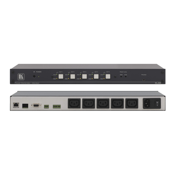
CAMBOARD Electronics Your PL-50 Power Controller - Monitor Figure 1: PL-50 Power Controller – Monitor Front Panel Figure 2: PL-50 Power Controller – Monitor (for Europe) Rear Panel Figure 3: PL-50 Power Controller – Monitor (for USA) Rear Panel www.camboard.de Tel. -
Page 10: Table 2: Pl-50 Power Controller - Monitor Features
Table 2: PL-50 Power Controller – Monitor Features Feature Function IR Receiver Window The red LED lights when receiving signals from the Kramer Infrared remote control transmitter POWER LED The red LED lights when the main power is ON OUT Channel... -
Page 11: Installing In A Rack
Pay particular If you are using a Kramer rack attention to situations where electricity is adapter kit (for a machine that is supplied indirectly (when the power cord is not not 19"), see the Rack Adapters... -
Page 12: Connecting The Pl-50 Power Controller - Monitor
Figure 4: Connecting the PL-50 1 Be sure that the power is switched OFF on each device before connecting it to your PL-50. After connecting all the devices to your PL-50, switch on the power of the PL-50, and then switch on the power of each device 2 You do not have to connect all the outlets. -
Page 13: Connecting The Relays
6.2.1 Connecting the ETHERNET Port Directly to a PC (Crossover Cable) You can connect the Ethernet port of the PL-50 to the Ethernet port on your PC, via a crossover cable with RJ-45 connectors. This type of connection is recommended for identifying the PL-50... -
Page 14: Connecting Via A Straight-Through Cable
Figure 7: Internet Protocol (TCP/IP) Properties Window 6.2.2 Connecting via a Straight-Through Cable You can connect the ETHERNET of the PL-50 to the Ethernet port on a network hub or network router, via a straight-through cable with RJ-45 connectors. www.camboard.de Tel. -
Page 15: Configuring The Ethernet Port Initially
Vertrieb von CAMBOARD Electronics Connecting the PL-50 Power Controller - Monitor 6.2.3 Configuring the Ethernet Port Initially To initially configure the Ethernet port, download the K-UPLOAD Ethernet configuration software . Extract the file to a folder and create a shortcut on your desktop to the file. -
Page 16: Figure 9: Connect Screen
3. Connect a USB cable from a USB port on the PC to the USB port on the PL-50 (you can also connect to the PC via the Ethernet or a serial connector). 4. Check USB as the connection method and select the com port from the USB drop down list. -
Page 17: Controlling Via The Embedded Web Pages
CAMBOARD Electronics Connecting the PL-50 Power Controller - Monitor 6.3 Controlling via the Embedded Web Pages The embedded Web page can be used to remotely operate the PL-50 via the Ethernet (see section 6.2). 6.3.1 Setting the Embedded Web Page Before you use the embedded Web pages to control the PL-50 via the Ethernet, check that the Java™... -
Page 18: Figure 13: Running The Application
The PL-50 front panel is displayed on your screen (see Figure 14). The Web embedded screens let you control the PL-50 via the Ethernet. The menu appears on the left side of the screen. The web embedded pages include a security system (see Section 6.3.8.1). -
Page 19: The Panel Screen
Vertrieb von CAMBOARD Electronics Connecting the PL-50 Power Controller - Monitor 6.3.2 The Panel Screen The Panel screen lets you select one or more channels in order to read the Standby or Active values and turn the power outlet ON/OFF:... -
Page 20: The Scheduler Screen
Vertrieb von CAMBOARD Electronics Connecting the PL-50 Power Controller - Monitor 6.3.3 The Scheduler Screen The Scheduler screen lets you schedule the operation of the outlets on a weekly basis. Figure 16 Table 4 define the Scheduler screen: Figure 16: The Scheduler Screen... -
Page 21: Figure 17: Scheduling The Outlets
ON/OFF order) You can clear a checkbox next to a time period setup in the scheduler table to delete a scheduled time period. Click Submit to save the schedule to the PL-50. HELP BOX This page lets you view and set the ON/OFF scheduling of the channel. Note, that the device will store the new scheduling only after you click "Submit". -
Page 22: The Channel Settings Screen
Vertrieb von CAMBOARD Electronics Connecting the PL-50 Power Controller - Monitor 6.3.4 The Channel Settings Screen Figure 18 Table 5 define the Channel Settings screen: Figure 18: The Channel Settings Screen Table 5: The Channel Settings Screen Features Feature... -
Page 23: The Alerts Screen
Vertrieb von CAMBOARD Electronics Connecting the PL-50 Power Controller - Monitor 6.3.5 The Alerts Screen Figure 19 Table 6 define the Alerts screen: Figure 19: The Alerts Screen Table 6: The Alerts Screen Features Feature Function Alert Triggers: Select the event that will trigger an alarm:... -
Page 24: Figure 20: Setting The Alarms
Vertrieb von CAMBOARD Electronics Connecting the PL-50 Power Controller - Monitor After setting the alarms, the Alerts screen appears as follows: Figure 20: Setting the Alarms In this example, Channel 2 and Channel 3 are enabled, and the events (TO... -
Page 25: The Power Measurement Screen
Vertrieb von CAMBOARD Electronics Connecting the PL-50 Power Controller - Monitor 6.3.6 The Power Measurement Screen Figure 21 Table 7 define the Power Measurement screen: Figure 21: The Power Measurement Screen Table 7: The Power Measurement Screen Features Feature... -
Page 26: The Power On/Off Order Screen
Vertrieb von CAMBOARD Electronics Connecting the PL-50 Power Controller - Monitor 6.3.7 The Power ON/OFF Order Screen The Power ON/OFF Order screen lets you determine the power ON and OFF order for channels that are scheduled to switch ON/OFF simultaneously. This is very convenient for systems that require a specific power up or shut down sequence. -
Page 27: Figure 23: Power On Order Example
Vertrieb von CAMBOARD Electronics Connecting the PL-50 Power Controller - Monitor In the example illustrated in Figure 23, the Power OFF Order is set from 5 to 1 with a 10 second delay time before each channel in the sequence is... -
Page 28: The Configurations Screen
Vertrieb von CAMBOARD Electronics Connecting the PL-50 Power Controller - Monitor 6.3.8 The Configurations Screen The Configurations page lets you view and change some Ethernet settings (see Figure 25 ) and also set the security level. To change Configuration definitions: 1. -
Page 29: Figure 26: Enable Security System
Vertrieb von CAMBOARD Electronics Connecting the PL-50 Power Controller - Monitor If the security system is disabled, the embedded Web pages can be accessed, and the parameters changed by anyone. Check the Security box to enable the security system. The following window... -
Page 30: The Security System
Vertrieb von CAMBOARD Electronics Connecting the PL-50 Power Controller - Monitor 6.3.8.1 The Security System Set the user password and Admin password (by default, the passwords for both User and Admin are empty fields). The security system includes three levels of security: •... -
Page 31: 6.4 Dip-Switch Settings
Remotely, from the Kramer Infrared Remote Control Transmitter or the infrared remote extension cable transmitter Powering up PL-50 unit, recalls the previous settings (that is, the state of the unit when it was powered down) from the non-volatile memory. 7.1 Calibrating via the Front Panel Buttons Prior to monitoring the PL-50 outlets, each outlet needs to be measured for its standby and Active modes. - Page 32 Vertrieb von CAMBOARD Electronics Operating Your PL-50 Power Controller – Monitor To set the Standby mode , do the following: 1. Press one or more OUT buttons to select the channels for which you want to measure the standby or active modes.
-
Page 33: Flash Memory Upgrade
4. Extract the file to a folder (for example, C:\Program Files\Kramer Flash). 8.1.2 Connect a PC to the PL-50 To connect a PC to the PL-50, make any one of the following connections: • Connect a serial cable from an RS-232 9-pin D-sub rear panel port on the PC to the PL-50. -
Page 34: 8.1.3 Update The Firmware
1 You can download and install the latest version of K-UPLOAD from http://www.kramerelectronics.com. 2 The screens appearing in this manual are examples of the process. The actual screens may differ in their content. www.camboard.de Tel. 07131 911201 ce-info@camboard.de KRAMER: SIMPLE CREATIVE TECHNOLOGY Fax 07131 911203... -
Page 35: Figure 32: Connection Time Out Message
im Vertrieb von CAMBOARD Electronics Flash Memory Upgrade 3. If you are upgrading using an Ethernet connection, check Ethernet. To reset the device address to the factory default address, click Default and the address 192.168.1.39 appears. If you are upgrading using: RS-232 check Serial, and select the COM port to connect ... -
Page 36: Figure 33: K-Upload Connected
After making any changes, click Save. 5. Click the Browse button, select the file from the Open window and then click Open. Figure 34: Open the Firmware File www.camboard.de Tel. 07131 911201 ce-info@camboard.de KRAMER: SIMPLE CREATIVE TECHNOLOGY Fax 07131 911203... -
Page 37: Figure 35: Warning Window
im Vertrieb von CAMBOARD Electronics Flash Memory Upgrade 6. Click the UPLOAD button to begin the file transfer. The Warning window appears: Figure 35: Warning Window 7. Click OK to continue. The upload progress appears in the Progress box: Figure 36: Upload Progress After loading the firmware file, wait for completion of the firmware upgrade: www.camboard.de Tel. -
Page 38: Figure 37: Restart Message
Flash Memory Upgrade 8. When the update is finished, the restart message appears: Figure 37: Restart Message 9. Click Restart now to close K-UPLOAD and remove the cable that connects the PL-50 to the PC. www.camboard.de Tel. 07131 911201 ce-info@camboard.de... -
Page 39: Changing The Device Parameters
CAMBOARD Electronics Technical Specifications Changing the Device Parameters To change the device parameters do the following: 1. Connect a PC to the PL-50 (see section 8.1.2). 2. Open K-UPLOAD (see Figure 30). 3. Click the Connect button to open the Connect window (see Figure 31). -
Page 40: 10 Kramer Protocol 3000
Vertrieb von CAMBOARD Electronics Kramer Protocol 3000 10 Kramer Protocol 3000 The Ethernet/USB/RS-232/RS-485 communication protocol lets you control the machine from any standard terminal software (for example, Windows® HyperTerminal Application). 10.1 Protocol 3000 Syntax Host message format: Start Address (optional) -
Page 41: Command Terms
Entering Commands: You can directly enter all commands using a terminal with ASCII communications software, such as HyperTerminal, Hercules, etc. Connect the terminal to the serial, Ethernet, or USB port on the Kramer device. To enter , press the Enter key. -
Page 42: Common Commands
Usage: Syntax Response SN SERIAL_NUMBER VERSION? Cmd Short Description Command Type Permission Read device firmware version Common-mandatory End User Usage: Syntax Response VERSION? VERSION MAJOR .MINOR .BUILD .REVISION www.camboard.de Tel. 07131 911201 ce-info@camboard.de KRAMER: SIMPLE CREATIVE TECHNOLOGY Fax 07131 911203... - Page 43 Vertrieb von CAMBOARD Electronics Kramer Protocol 3000 FACTORY Cmd Short Description Command Type Permission Reset to factory default config Common Administrator Usage: Syntax Response NAME Cmd Short Description Command Type Permission Set machine (DNS) name Common Administrator Usage: Syntax...
-
Page 44: Result And Error Codes
Query Login Security No Security Usage: Syntax Response LOGIN? LOGIN ID LOGOUT Cmd Short Description Command Type Permission Logout Security No Security Usage: Syntax Response LOGOUT LOGOUT RESULT www.camboard.de Tel. 07131 911201 ce-info@camboard.de KRAMER: SIMPLE CREATIVE TECHNOLOGY Fax 07131 911203... -
Page 45: Network Setting Commands
Vertrieb von CAMBOARD Electronics Kramer Protocol 3000 PASS Cmd Short Description Command Type Permission Set password Security Administrator Usage: Syntax Response PASS ID , PASS PASS ID , PASS RESULT PASS? Cmd Short Description Command Type Permission Query password... - Page 46 Response NET-IP IP_ADDRESS, (ex: 192.168.001.001) NET-IP IP_ADDRESS RESULT NET-IP? Cmd Short Description Command Type Permission NTIP? Get IP address Ethernet End User Usage: Syntax Response NET-IP? NET-IP IP_ADDRESS www.camboard.de Tel. 07131 911201 ce-info@camboard.de KRAMER: SIMPLE CREATIVE TECHNOLOGY Fax 07131 911203...
-
Page 47: Instruction Codes
Vertrieb von CAMBOARD Electronics Kramer Protocol 3000 NET-MAC? Cmd Short Description Command Type Permission NTMC? Read MAC address Ethernet End User Usage: Syntax Response NET-MAC? NET-MAC MAC_ADDRESS NET-MASK Cmd Short Description Command Type Permission NTMSK Set subnet mask Ethernet... - Page 48 Cmd Short Description Command Type Permission Alert Registration PL-50 Administrator Usage: Syntax Response ALERT-REG? CHNL ALERT-REG? CHNL ,EVENT ,ACTION CHNL = (1-5) EVENT = (TO_OFF,TO_ON,TO_FULL,TO_STBY,TO_NONE,ANY_CHANGE) ACTION = (NO_ALERT,ALARM, ALL_ALERTS) www.camboard.de Tel. 07131 911201 ce-info@camboard.de KRAMER: SIMPLE CREATIVE TECHNOLOGY Fax 07131 911203...
- Page 49 Vertrieb von CAMBOARD Electronics Kramer Protocol 3000 ALERT-REG? Cmd Short Description Command Type Permission Query Alert Registration PL-50 User Usage: Syntax Response ALERT-REG? CHNL ALERT-REG? CHNL ,EVENT ,ACTION CHNL = (1-5) EVENT = (TO_OFF,TO_ON,TO_FULL,TO_STBY,TO_NONE,ANY_CHANGE) ACTION = (NO_ALERT,ALARM, ALL_ALERTS) MEASURE...
- Page 50 SWITCH-ORDER-DELAY ON/OFF, 0-255 sec SWITCH-ORDER-DELAY ON/OFF, 0-255 sec RESULT ON/OFF = ON or OFF SWITCH-ORDER-DELAY? Cmd Short Description Command Type Permission Query the switch order delay PL-50 User Usage: Syntax Response SWITCH-ORDER-DELAY? ON/OFF SWITCH-ORDER-DELAY ON/OFF, 0-255 sec = ON or OFF ON/OFF www.camboard.de...
- Page 51 EXCLUSION OF DAMAGES The liability of Kramer for any effective products is limited to the repair or replacement of the product at our option. Kramer shall not be liable for: 1. Damage to other property caused by defects in this product, damages based upon inconvenience, loss of use of the product, loss of time, commercial loss;...
- Page 52 Vertrieb von CAMBOARD Electronics For the latest information on our products and a list of Kramer distributors, visit our Web site: www.kramerelectronics.com, where updates to this user manual may be found. We welcome your questions, comments and feedback. Safety Warning: Disconnect the unit from the power supply before opening/servicing.
Need help?
Do you have a question about the PL-50 and is the answer not in the manual?
Questions and answers