
Subscribe to Our Youtube Channel
Related Manuals for Kramer 860


Summary of Contents for Kramer 860
- Page 1 USER MANUAL MODEL: 860 Controller Control Software for Signal Generator & Analyzer (Bench/Portable Version) P/N: 2900-301712 Rev 1 www.kramerav.com...
-
Page 2: Table Of Contents
Connect via Ethernet (Bench Version Only) Connect via RS-232 SOFTWARE OPERATION Operational Mode EDID Management (Analyzer/Pattern) Output Resolution (Analyzer/Pattern) Test Pattern (Pattern Mode Only) Control Panel (Analyzer/Pattern) Real-time Monitoring (Analyzer/Pattern) Cable Testing (Portable Version Only) ACRONYMS 860 Controller – Contents... -
Page 3: Overview
Kramer Technology assumes no responsibility for any inaccuracies that may be contained in this document. Kramer also makes no commitment to update or to keep current the information contained in this document. -
Page 4: Introduction
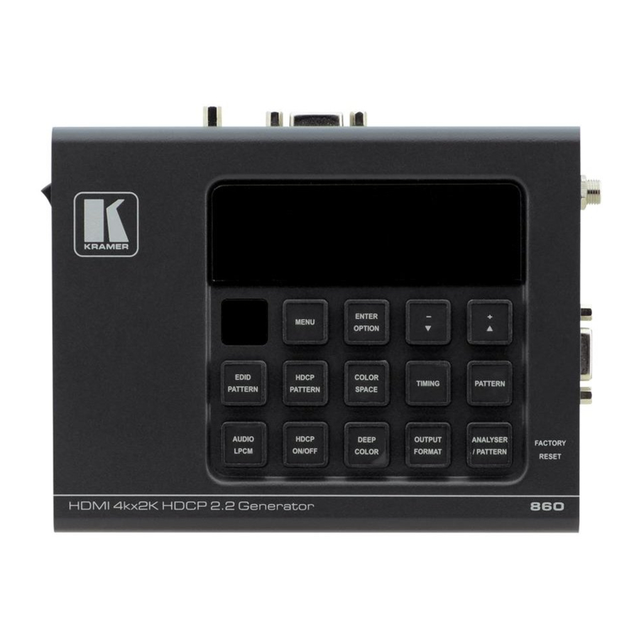
Introduction 860 Controller is fully featured control software for use with the 860 (Benchtop Version) and 861 (Portable Version) Signal Generator & Analyzer products. This software is designed for installation and operation on a standard Windows (7, 8, 8.1, 10) PC or Laptop. This software provides full control over the Signal Generator &... -
Page 5: Connection
CONNECTION 860 Controller software can connect to the Bench Version of the Signal Generator & Analyzer via RS-232 or Ethernet or to the Portable Version via RS-232 (Using the Micro-USB port). Please follow the steps below to connect using the appropriate method for the device you wish to control. -
Page 6: Connect Via Rs-232
Step 1: To set the 861 to be controlled by RS-232 go to Setup → USB Port → select RS- 232: ▪ Start the 860 Controller software by clicking on it in the Start Menu. ▪ If you are attempting to connect to the Portable Version, remember to change the USB connection to “RS-232”... - Page 7 Step 4: Select the correct COM port of the unit from the dropdown in the 860 Controller software and the software should automatically connect to the unit. If it is successful the connection button will turn green ( ) and the “Not Linked” message will change to read “Accepted”.
-
Page 8: Software Operation
All major functions of the Signal Generator & Analyzer units are accessible from the tabs and buttons provided in the main window of the 860 Controller software. These include operation mode selection, EDID management, output resolution selection, pattern selection, function control, sink/source monitoring, and cable testing (Portable Version only). -
Page 9: Edid Management (Analyzer/Pattern)
If at any time you feel that the currently displayed data is not correct or up to date (due to direct manual operation of the unit, for example) you may click on the Refresh button to force a re-download of the unit’s data to the software. Clicking on the Command Monitor button ( ) will open a second window that displays all command responses from the connected unit. -
Page 10: Output Resolution (Analyzer/Pattern)
4. WRITE: Writes the EDID from the left window to the EDID destination selected in the “Write to:” dropdown menu. 5. READ: Reads the EDID from the currently selected source/sink listed in the “Read from:” dropdown menu and places it into the right window. 6. - Page 11 The output resolution that is currently in use is displayed near the top of the window. Selecting a new resolution for output can be done in one of two ways. Click on a resolution in the “Favorite Timings” list or find the resolution in the list on the left and double-click the resolution name.
-
Page 12: Test Pattern (Pattern Mode Only)
Test Pattern (Pattern Mode Only) This tab provides control over the unit’s test patterns and allows setting “Favorite Patterns” for quick selection. This function is only available in Pattern Mode. The image below is from the Bench Version of the unit. The list of available patterns for the Portable Version is more limited. -
Page 13: Control Panel (Analyzer/Pattern)
Control Panel (Analyzer/Pattern) This tab provides control over the unit’s additional features, functions and settings that are not covered by the other tabs. The available controls change depending on the unit’s current operational mode (Analyzer or Pattern), and which functions are appropriate based on the unit’s current output resolution and pattern selection. -
Page 14: Real-Time Monitoring (Analyzer/Pattern)
Real-time Monitoring (Analyzer/Pattern) This tab provides access to a full suite of real-time monitoring and analysis functions covering a wide range of data from both the input and output. The available Real-time Monitor categories are: 1. SYSTEM: Basic source, sink and unit signal information. 2. -
Page 15: Cable Testing (Portable Version Only)
Cable Testing (Portable Version Only) The Portable Version of the Signal Generator & Analyzer includes a cable testing function to help quantify the general feature support and error resistance capabilities of the cable being tested. The Cable Test tab contains the controls required to perform a cable test. To perform a cable test: Step 1: Connect the cable to be tested to both the HDMI input and HDMI output of the unit. -
Page 16: Acronyms
ACRONYMS ACRONYM COMPLETE TERM Audio Return Channel ASCII American Standard Code for Information Interchange Cat.5e Enhanced Category 5 cable Cat.6 Category 6 cable Cat.6A Augmented Category 6 cable Cat.7 Category 7 cable Consumer Electronics Control Command-Line Interface Decibel DHCP Dynamic Host Configuration Protocol Digital Visual Interface EDID Extended Display Identification Data... - Page 17 www.kramerav.com info@kramerav.com...
Need help?
Do you have a question about the 860 and is the answer not in the manual?
Questions and answers