
Related Manuals for Kramer SL-280


Summary of Contents for Kramer SL-280
- Page 1 USER MANUAL MODEL: SL-280 Master / Room Controller Kramer Control Brain P/N: 2900-300567 Rev 1 www.KramerAV.com...
-
Page 2: Table Of Contents
Contents Introduction Getting Started Overview Typical Applications Controlling your SL-280 Defining the SL-280 Master / Room Controller Kramer Control Brain Installing in a Rack Connecting SL-280 Connecting the Relay Ports Remote Operation via the Web Pages Loading and Saving Configurations... -
Page 3: Introduction
Kramer Electronics Ltd. Introduction Welcome to Kramer Electronics! Since 1981, Kramer Electronics has been providing a world of unique, creative, and affordable solutions to the vast range of problems that confront the video, audio, presentation, and broadcasting professional on a daily basis. In recent years, we have... -
Page 4: Overview
European Advanced Recycling Network (EARN) and will cover any costs of treatment, recycling and recovery of waste Kramer Electronics branded equipment on arrival at the EARN facility. For details of Kramer’s recycling arrangements in your particular country go to our recycling pages at www.kramerav.com/support/recycling... -
Page 5: Typical Applications
• Auditoriums • Government meeting rooms • Court rooms • Command and control applications Controlling your SL-280 Control your SL-280 directly via one of the following: • Ethernet using built-in, user-friendly web pages (see Remote Operation via the Web Pages on page 9). -
Page 6: Defining The Sl-280 Master / Room Controller Kramer Control Brain
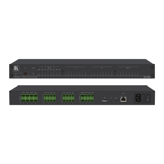
Kramer Electronics Ltd. Defining the SL-280 Master / Room Controller Kramer Control Brain This section defines SL-280. Figure 1: SL-280 Master / Room Controller Kramer Control Brain Front Panel Feature Function POWER LED Lights green when powered on. SERVICE Micro USB Connect to a PC to send P3K commands and perform a firmware upgrade. - Page 7 Kramer Electronics Ltd. Figure 2: SL-280 Master / Room Controller Kramer Control Brain Rear Panel Feature Function SERIAL Ports (1–8) Connect to up to 8 serial controlled devices, for Ethernet-to-RS232 Terminal Block bidirectional tunneling. IR Ports (1–8) Connect to up to 8 IR emitters or blasters.
-
Page 8: Installing In A Rack
Kramer Electronics Ltd. Installing in a Rack This section provides instructions for rack mounting SL-280. Before installing in a rack, verify that the environment is within the recommended range: • Operation temperature – 0° to 40°C (32 to 104°F). •... -
Page 9: Connecting Sl-280
Kramer Electronics Ltd. Connecting SL-280 Always switch off the power to each device before connecting it to your SL-280. After connecting your SL-280, connect its power and then switch on the power to each device. Figure 3: Connecting SL-280 To connect SL-280 as illustrated in the example in... -
Page 10: Connecting The Relay Ports
Connect the device to the C (Common) and NO terminals of the relevant port. To connect ports 1 and 5 as NC: • Connect the device to the C and NC terminals of the relevant port. SL-280 – Connecting SL-280... -
Page 11: Remote Operation Via The Web Pages
Remote Operation via the Web Pages SL-280 embedded webpages enable you to define device settings, configure communication parameters, configure port settings, define security parameters, and view activity logs. The specific parameter values shown in screenshots of this manual are merely representative. -
Page 12: Loading And Saving Configurations
3. Browse to the required location to which to save the file. 4. Enter the required name for the saved preset. 5. Click OK. The current configuration is saved. When using Chrome, the file is automatically saved in the Downloads folder. SL-280 – Remote Operation via the Web Pages... -
Page 13: Viewing Connected Clients Information
S/R – Whether or not Send Replies is enabled for the port (see Configuring the Serial Ports on page 14). Modifying Device Settings SL-280 web pages enable you to modify the following device settings: • Device Name • Time and Date Settings SL-280 – Remote Operation via the Web Pages... - Page 14 2. In the Time and Date area, if Use time server (NTP) is set to ON, click OFF and click in the relevant fields to define the date, time and time zone. –OR– 3. Click the ON button, enter the time server address in the Time server address field, and click Set. SL-280 – Remote Operation via the Web Pages...
-
Page 15: Defining Ip Settings
Figure 8: Communication Page 2. In the Ethernet section, view the MAC address. 3. Click the DHCP OFF button. 4. Enter the required IP settings in the relevant fields. 5. Click Set. SL-280 – Remote Operation via the Web Pages... -
Page 16: Configuring The Serial Ports
27). 7. Select whether or not to send replies on the port to a new connected client by default, (see Viewing Connected Clients Information on page 11). 8. Click Save Changes. SL-280 – Remote Operation via the Web Pages... -
Page 17: Configuring I/O Ports
Configuring a Digital Out Trigger Type on page 17) • Analog Input (see Configuring an Analog In Trigger Type on page 18) The settings available on the page, change depend on which trigger type is selected. SL-280 – Remote Operation via the Web Pages... - Page 18 When the pull-up resistor is disabled, the port state is low and to be triggered it must be pulled high by the externally connected sensor. 3. Define the Min and Max for the Threshold VDC range (threshold voltage at which the port changes state) and click Set. SL-280 – Remote Operation via the Web Pages...
- Page 19 When the pull-up resistor is disabled, the port state is low and to set it high, you must click High for the Current Status. Make sure that the current in this configuration does not exceed 100mA. SL-280 – Remote Operation via the Web Pages...
- Page 20 This value is the number of steps that the analog input signal is divided into. To calculate the voltage of each step, use the following formula: Voltage of one step = 30V / number of steps SL-280 – Remote Operation via the Web Pages...
-
Page 21: Changing The State Of A Relay Port
When relays 1 and 5 are connected as NC (see Connecting the Relay Ports on page 8), the Current status buttons are reversed. Clicking Open closes the relay and clicking Close opens the relay. SL-280 – Remote Operation via the Web Pages... -
Page 22: Teaching Ir Commands
5. Position the IR remote control approximately 5cm to 7cm (2in to 2.7in) from the front panel. 6. Send a command with the remote control. The command string received during the process appears in the Command received box. SL-280 – Remote Operation via the Web Pages... -
Page 23: Activating Device Security
1. Click Security on the left side of the web page (Figure The Security page appears. Figure 16: Security Page 2. Click ON. A confirmation message appears. Figure 17: Security Confirmation Message SL-280 – Remote Operation via the Web Pages... - Page 24 6. Click Security on the left side of the web page. The Security page appears with the Change Password settings. Figure 19: Security Activated Page 7. If required, change the password and click Change. SL-280 – Remote Operation via the Web Pages...
-
Page 25: Using The Log
3. Select any of the options in the Log Config list to define which types of events are recorded. The display may not update automatically. Click Refresh to update the display. SL-280 – Remote Operation via the Web Pages... -
Page 26: About Us Page
Kramer Electronics Ltd. About Us Page Click About on the left side of the web page (Figure 5).to display the web page version and Kramer company information. Figure 21: About Us Page SL-280 – Remote Operation via the Web Pages... -
Page 27: Resetting And Upgrading Firmware
2. Release the RESET button. Wait for the reset process to complete. The device is reset to the factory default settings. Upgrading the Firmware For instructions on upgrading the firmware see the “Kramer K-Upload User Manual”. SL-280 – Resetting and Upgrading Firmware... -
Page 28: Technical Specifications
2.6kg (5.7lbs) approx. Accessories Included Power cord, rack ears Optional For optimum range and performance use the recommended USB, Ethernet, serial and IR Kramer cables available at www.kramerav.com/product/ SL-280 Specifications are subject to change without notice at www.kramerav.com SL-280 – Technical Specifications... -
Page 29: Default Communication Parameters
Front panel buttons Press and hold the RESET button on the rear panel for 6 seconds. Resetting to Factory Default Settings on page 25. Default Security Parameters • Default User Name: Admin • Default Password: adminpw SL-280 – Technical Specifications... -
Page 30: Protocol 3000
You can enter commands directly using terminal communication software (e.g., Hercules) by connecting a PC to the serial or Ethernet port on SL-280. To enter CR press the Enter key (LF is also sent but is ignored by the command parser). -
Page 31: Understanding Protocol 3000
Spaces between parameters or command terms are ignored. Commands in the string do not execute until the closing character is entered. A separate response is sent for every command in the chain. SL-280 – Protocol 3000... -
Page 32: Kramer Protocol 3000 Syntax
Kramer Electronics Ltd. Kramer Protocol 3000 Syntax The Kramer Protocol 3000 syntax uses the following delimiters: CR = Carriage return (ASCII 13 = 0x0D) • LF = Line feed (ASCII 10 = 0x0A) • SP = Space (ASCII 32 = 0x20) •... -
Page 33: Protocol 3000 Commands
~nn@BUILD-DATESPdateSPtimeCR LF Parameters date – Format: YYYY/MM/DD where YYYY = Year, MM = Month, DD = Day time – Format: hh:mm:ss where hh = hours, mm = minutes, ss = seconds Response Triggers Notes Example #BUILD-DATE?<CR> SL-280 – Protocol 3000... - Page 34 2. Multi-line: ~nn@HELPSPcommand:CR LFdescriptionCR LFUSAGE:usageCR LF Parameters command_name – name of a specific command Response Triggers Notes Example 1. Get a list of all SL-280 commands: #HELP<CR> 2. Get help for the ETH-PORT command: #HELP ETH-PORT<CR> SL-280 – Protocol 3000...
- Page 35 Used for advanced troubleshooting. Helps find error root causes and gets details not displayed in the error code number. Example Get the last 20 lines of message logs: #LOG-TAIL?<CR> Get the last 50 lines of message logs: #LOG-TAIL? 50<CR> SL-280 – Protocol 3000...
- Page 36 The machine name is not the same as the model name. The machine name is used to identify a specific machine or a network in use (with DNS feature on). Example Set the DNS name of the device to “room-442”: #NAME room-442<CR> SL-280 – Protocol 3000...
- Page 37 Response ~nn@NAME-RSTSPOKCR LF Parameters Response Triggers Notes Factory default of machine (DNS) name is “SL-280-XXXXXXX”, where XXXXXXX = the last 7 digits of the serial number. Example Reset the DNS name of the device to the factory default: #NAME-RST<CR> PROT-VER...
- Page 38 Transparency Set: Get: End User Public Description Syntax Set: Get device serial #SN?CR Get: number Response ~nn@SNSPserial_numberCR LF Parameters serial_number–14 digits, factory assigned Response Triggers Notes This device has a 14 digit serial number. Example #SN?<CR> SL-280 – Protocol 3000...
- Page 39 This parameter is maintained only for backward compatibility. The TIME command sets the device time without considering these settings. Example Set device local time to US EST (Eastern Standard Time = -5 UTC/GMT): #TIME-LOC -5,0<CR> SL-280 – Protocol 3000...
- Page 40 Set a network configuration NET-DHCP Set/get DHCP mode NET-DNS Get DNS name server NET-GATE Set/get gateway IP NET-IP Set/get IP address NET-MAC Get MAC address NET-MASK Set/get subnet mask TIME-SRV Get/set time server UART Get/set com port configuration SL-280 – Protocol 3000...
- Page 41 – device name Response Triggers After execution, notification is sent containing beacon information. Notes There is no Set command. The port_id parameter is not necessary and can be omitted. Example Get beacon information for port 0: #BEACON-INFO? 0<CR> SL-280 – Protocol 3000...
- Page 42 – network mask, in the following format: xxx.xxx.xxx.xxx gateway – network gateway, in the following format: xxx.xxx.xxx.xxx Response Triggers Notes Example Set the device network parameters to IP address 192.168.113.10, net mask 255.255.0.0, and gateway 192.168.0.1: #NET-CONFIG 0,192.168.113.10,255.255.0.0,192.168.0.1<CR> SL-280 – Protocol 3000...
- Page 43 If dns_id is out of the defined DNS range, Error Code #3 (ERR_PARAMETER_OUT_OF_RANGE) is returned. If no dns_id is defined, Error Code #3 is returned for any dns_id. Example Get the IP address of DNS name server 1: #NET-DNS? 0<CR> SL-280 – Protocol 3000...
- Page 44 Get: Get IP address Response ~nn@NET-IPSPip_addressCR LF Parameters ip_address – IP address, in the following format: xxx.xxx.xxx.xxx Response Triggers Notes Consult your network administrator for correct settings. Example Set the IP address to 192.168.1.39: #NET-IP 192.168.001.039<CR> SL-280 – Protocol 3000...
- Page 45 – Subnet mask address. Format: xxx.xxx.xxx.xxx Response Triggers The subnet mask limits the Ethernet connection within the local network. Consult your network administrator for correct settings. Notes Example Set the subnet mask to 255.255.0.0: #NET-MASK 255.255.000.000<CR> SL-280 – Protocol 3000...
- Page 46 – time server IP address or hostname. IP must be, in the following format: xxx.xxx.xxx.xxx time_server_sync_hour – not in use: 0 server_status – ON/OFF Response Triggers Notes This command sets up the NTP server. Example Set time server with IP address of 128.138.140.44 to ON: #TIME-SRV 1, 128.138.140.44,0<CR> SL-280 – Protocol 3000...
- Page 47 Set/get HW GPIO step GPIO-THR Set/get HW GPIO threshold voltage GPIO-VOLT Get HW GPIO voltage level IR-LEARN Send IR learning command IR-SND Send IR command to port IR-STOP Send IR stop command to port RELAY-STATE Set/get relay state SL-280 – Protocol 3000...
- Page 48 TCP_keep_alive_timing – every x seconds the device sends an empty string to TCP client ("/0"): 0–3600 seconds Response Triggers Notes This command gets tunneling port routing. Every SERIAL port can send or receive data from the ETH port. Example Get tunneling port routing through SERIAL port number 1: #COM-ROUTE? 1<CR> SL-280 – Protocol 3000...
- Page 49 Description Syntax Remove a #COM-ROUTE-REMOVE␠ComNum␍ Set: communication route tunnel connection Get: Response ~nn@COM-ROUTE-REMOVE␠Com_Num␍␊ Parameters Com_Num – SERIAL port number: 1–8 Response Triggers Notes Example Remove communication route tunnel connection from SERIAL port number 3: #COM-ROUTE-REMOVE 3<CR> SL-280 – Protocol 3000...
- Page 50 ETH_rep_en – 1 (COM port sends replies to new clients) 0 (COM port does not send replies to new clients) Wired – 1 (wired connection), 0 (not wired connection) Response Triggers Notes Example Get parameters for all open tunnels: #ETH-TUNNEL? *<CR> Get parameters for tunnel 1: #ETH-TUNNEL? 1<CR> SL-280 – Protocol 3000...
- Page 51 The device uses this command to notify the user of whenever there is a change regarding the state. Example Set state for digital I/O port number 1 to high: #GPIO-STATE 1,1<CR> SL-280 – Protocol 3000...
- Page 52 This command is only relevant for digital input. There must be a minimum of 800 millivolts between the low and the high levels. Example Set I/O port number 1 voltage low level to 500 millivolts and high level to 2000 millivolts: #GPIO-THR 1,500,2000<CR> SL-280 – Protocol 3000...
- Page 53 IR_Status – 0 (Sent), 1 (Stop), 2 (Done), 3 (Busy), 4 (Wrong Parameter), 5 (Nothing to Stop), 6 (Start), 7 (Timeout), 8 (Error) Response Triggers Notes Example Send IR learning command PowerToggle, with a 30 second timeout: #IR-LEARN PowerToggle,30<CR> SL-280 – Protocol 3000...
- Page 54 Transmit IR Power button command with ID of 25 and name PowerTog from port 1; command is repeated 1 time, the total packets is 1,packet/chunk serial number is 1: #IR-SND 1,25,PowerTog,1,1,1,0000,006e,0022,0002,0156,00ae,0016,0016,0016,0041,0016,0016 ,0016,0041,0016,0016,0016,0016,0016,0016,0016,0016,0016,0016,0016,0041,0016,001 6,0016,0041,0016,0016,0016,0016,0016,0016,0016,0016,0016,0016,0016,0041,0016,00 16,0016,0041,0016,0016,0016,0016,0016,0016,0016,0016,0016,0041,0016,0016,0016,0 041,0016,0016,0016,0041,0016,0041,0016,0041,0016,0041,0016,069c,0156,0057,0016, 0e56<CR> SL-280 – Protocol 3000...
- Page 55 When relays 1 and 5 are connected as NC (Normally Closed) (see Connecting the Relay Ports on page 8), the RelayState parameter is reversed: 0 (closed), 1 (open). Example Set Relay port number 2 state to closed: #RELAY-STATE 2,1<CR> SL-280 – Protocol 3000...
- Page 56 Permission Transparency Set: Administrator Public Get: Description Syntax Set: Delete file #DEL␠file_name␍ Get: Response ~nn@DEL␠file_name␍␊ Parameters file_name – name of file to delete Response Triggers Notes File names are case-sensitive. Example Delete Setup file: #DEL Setup<CR> SL-280 – Protocol 3000...
- Page 57 – file size in bytes. A file can take more space on device memory file_id – internal ID for file in file system free_size – free space in bytes in device file system Response Triggers Notes Example List files in device: #DIR<CR> SL-280 – Protocol 3000...
- Page 58 Get: Administrator Public Description Syntax Set: Get file system free Get: #FS-FREE?␍ space Response ~nn@FS_FREE␠free_size␍␊ Parameters free_size – free size in device file system in bytes Response Triggers Notes Example Get file system free space: #FS-FREE?<CR> SL-280 – Protocol 3000...
- Page 59 – name of file to get contents contents – byte stream of file contents file_size – size of file (device sends it in response to give user a chance to get ready) Response Triggers Notes Example Get file: #GET file_name<CR> SL-280 – Protocol 3000...
- Page 60 The permission system works only if security is enabled with the SECUR command. It is not mandatory to enable the permission system in order to use the device. Example Set the protocol permission level to Admin (when the password defined in the PASS command is 33333): #LOGIN Admin,33333<CR> SL-280 – Protocol 3000...
- Page 61 – password for the login_level. Up to 15 printable ASCII chars. Response Triggers Notes The default password is an empty string Example Set the password for the Admin protocol permission level to 33333: #PASS Admin,33333<CR> SL-280 – Protocol 3000...
- Page 62 Parameters security_mode – 1 (On / enable security), 0 (Off / disable security) Response Triggers Notes The permission system works only if security is enabled with the SECUR command. Example Enable the permission system: #SECUR 0<CR> SL-280 – Protocol 3000...
-
Page 63: License Information
The license and distribution terms for any publically available version or derivative of this code cannot be changed. i.e. this code cannot simply be copied and put under another distribution license [including the GNU Public License.] SL-280 – License Information... - Page 64 Sections 1 and 2 above provided that you also do one of the following: a) Accompany it with the complete corresponding machine-readable source code, which must be distributed under the terms of Sections 1 and 2 above on a medium customarily used for software interchange; or, SL-280 – License Information...
- Page 65 INABILITY TO USE THE PROGRAM (INCLUDING BUT NOT LIMITED TO LOSS OF DATA OR DATA BEING RENDERED INACCURATE OR LOSSES SUSTAINED BY YOU OR THIRD PARTIES OR A FAILURE OF THE PROGRAM TO OPERATE WITH ANY OTHER PROGRAMS), EVEN IF SUCH HOLDER OR OTHER PARTY HAS BEEN ADVISED OF THE POSSIBILITY OF SUCH DAMAGES. SL-280 – License Information...
- Page 66 What Kramer Electronics Will Do Kramer Electronics will, at its sole option, provide one of the following three remedies to whatever extent it shall deem necessary to satisfy a proper claim under this limited warranty: Elect to repair or facilitate the repair of any defective parts within a reasonable period of time, free of any charge for the necessary parts and labor to complete the repair and restore this product to its proper operating condition.
- Page 67 SAFETY WARNING Disconnect the unit from the power supply before opening and servicing For the latest information on our products and a list of Kramer distributors, visit our Web site where updates to this user manual may be found. We welcome your questions, comments, and feedback.
Need help?
Do you have a question about the SL-280 and is the answer not in the manual?
Questions and answers