
Subscribe to Our Youtube Channel
Related Manuals for Kramer SL-14RC


Summary of Contents for Kramer SL-14RC
- Page 1 K R A ME R E LE CT R O N IC S L T D . USER MANUAL MODELS: SL-14RC Master Controller RC-3TB Remote Control Panel (Optional) P/N: 2900-000598 Rev 5...
-
Page 3: Table Of Contents
Installing the Front Panel Button Caps and Labels Replacing the Front Panel Button Labels Technical Specifications Figures Figure 1: SL-14RC Master Controller Front Panel Figure 2: SL-14RC Master Controller Rear Panel Figure 3: RC-3TB Remote Control Panel Components Figure 4: Connecting the SL-14RC Master Controller... -
Page 4: Introduction
GROUP 7: Scan Converters and Scalers; GROUP 8: Cables and Connectors; GROUP 9: Room Connectivity; GROUP 10: Accessories and Rack Adapters and GROUP 11: Sierra Products. Congratulations on purchasing your Kramer SL-14RC Master Controller, which is ideal for the following typical applications: •... -
Page 5: Getting Started
(often associated with low quality cables) • Avoid interference from neighboring electrical appliances that may adversely influence signal quality • Position your Kramer SL-14RC away from moisture, excessive sunlight and dust SL-14RC - Getting Started... -
Page 6: Overview
Overview The SL-14RC is a highly versatile master room controller that acts as an all-in-one extended remote control panel for control of A/V equipment—especially projectors and associated equipment—in any room (such as classrooms, boardrooms, or auditoriums). It streamlines operations and simplifies control by integrating audio, video, and computer-video sources into a centralized system. -
Page 7: Defining The Sl-14Rc Master Controller
Defining the SL-14RC Master Controller This section defines the SL-14RC. SL-14RC - Overview... -
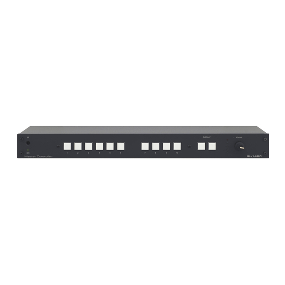
Page 8: Figure 1: Sl-14Rc Master Controller Front Panel
Figure 1: SL-14RC Master Controller Front Panel Feature Function IR Receiver Accepts IR control ON LED Lights during IR activity Configurable Button Switches 1-10 Function is programmed by the K-Config Configuration software DISPLAY Configurable Button switches 11 and 12 Function is programmed by the K-Config Configuration software... -
Page 9: Figure 2: Sl-14Rc Master Controller Rear Panel
Figure 2: SL-14RC Master Controller Rear Panel Feature Function K-NET Connector Connect the GND pin to the Ground connection; pin B (-) and pin A (+) are for RS-485, and the +12V pin is for powering the unit The ground connection is sometimes connected to the shield of the RS-485 cable (in most... -
Page 10: Defining The Rc-3Tb Remote Control Panel (Optional)
Mounting Holes 2 holes for mounting the RC-3TB to the PTBUS-3 or TBUS-6W Button 1 Function is always assigned to button 12 on SL-14RC Buttons 2 and 3 Function is assigned by the rotary switch position K-NET Connector Connects to either SL-14RC or additional RC-3TB... - Page 11 For example, if the rotary switch is in position 4, the 3 buttons on the RC-3TB will duplicate the functions of buttons 12, 8, and 10 on the SL-14RC. That is, in this example, pressing button 1 on the RC-3TB has the same effect as pressing button...
-
Page 12: Installing In A Rack
Installing in a Rack This section provides instructions for rack mounting the unit. SL-14RC - Installing in a Rack... -
Page 13: Connecting The Sl-14Rc
Connecting the SL-14RC Always switch off the power to each device before connecting it to your SL-14RC. After connecting your SL-14RC, connect its power and then switch on the power to each device. To connect the SL-14RC as illustrated in the example in Figure 1. -
Page 14: Connecting The Rs-232 Interface
Figure 4: Connecting the SL-14RC Master Controller Connecting the RS-232 Interface To connect an AV device to the SL-14RC using the RS-232 port, connect the RS-232 9-pin D-sub port on your AV device to the RS-232 terminal block on the... -
Page 15: Connecting The Ethernet Port
To connect the SL-14RC to a network: 1. Connect the Ethernet port of the SL-14RC to the Ethernet port on a network hub or network router, via a straight cable with RJ-45 connectors. 2. At the other end, connect the Internet to a PC running Site-CTRL. -
Page 16: Figure 7: Daisy-Chaining Multiple Rc-3Tb Panels
Only the last RC-3TB in the chain should be terminated. 6.3.2 Daisy-Chaining Multiple RC-3TB Remote Control Panels The wiring of two RC-3TB panels to the K-NET port on the SL-14RC is shown in Figure 6. Connection of more than two RC-3TB panels follows the same principle. -
Page 17: Operating The Sl-14Rc
Operating the SL-14RC You can operate your SL-14RC using: • Front panel buttons. These are configured using the K-Config software. For instructions on using the software, see the K-Config Software Guide available from our Web site at www.kramerelectronics.com • RC-3TB Remote Control Panels (optional) •... -
Page 18: Front Panel Button Caps And Labels
Front Panel Button Caps and Labels The SL-14RC is supplied with a button label sheet and 12 clear, button caps to house the labels. Figure 8 illustrates a sample button label sheet. SL-14RC - Front Panel Button Caps and Labels... -
Page 19: Figure 8: Sample Button Label Sheet
Figure 8: Sample Button Label Sheet SL-14RC - Front Panel Button Caps and Labels... -
Page 20: Installing The Front Panel Button Caps And Labels
2. Remove the supplied button caps from the bag and insert the labels into the button caps. 3. Taking care that the button is oriented correctly, gently press the button cap on to the required button of the SL-14RC. 4. Repeat for all the button caps. Replacing the Front Panel Button Labels Note: The button caps are a press fit on the buttons and must be removed carefully or the buttons may be damaged. -
Page 21: Technical Specifications
HUMIDITY: 10% to 90%, RHL non-condensing DIMENSIONS 48.3cm x 11.5cm x 1U (19" x 4.5" x 1U) W, D, H (SL-14RC) 8.9cm x 2.1cm x 2.3cm (3.5" x 0.8" x 0.9”) W, D, H (RC-3TB) WEIGHT: 0.6kg (1.4lbs) approx. (SL-14RC) 0.1kg (0.22lbs) approx. - Page 22 1. Any product which is not distributed by us or which is not purchased from an authorized Kramer dealer. If you are uncertain as to whether a dealer is authorized, please contact Kramer at one of the agents listed in the Web site www.kramerelectronics.com.
- Page 23 For the latest information on our products and a list of Kramer distributors, visit our Web site where updates to this user manual may be found. We welcome your questions, comments, and feedback. Web site: www.kramerelectronics.com E-mail: info@kramerel.com SAFETY WARNING...
Need help?
Do you have a question about the SL-14RC and is the answer not in the manual?
Questions and answers