
Related Manuals for Valmar EASY 3 TTi


Summary of Contents for Valmar EASY 3 TTi
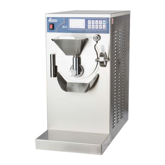
- Page 1 HANDLING, OPERATING AND MAINTENANCE GUIDE FOR ICE CREAM PRODUCTION APPLIANCE Model EASY TTi...
-
Page 3: Table Of Contents
TABLE OF CONTENTS INSTRUCTIONS ON HOW TO USE THE GUIDE ........6 SYMBOLS USED IN THE GUIDE ............7 GENERAL FEATURES AND SPECIFICATIONS ........8 GENERAL FEATURES ................ 8 IDENTIFICATION OF THE APPLIANCE ........... 10 TECHNICAL SPECIFICATIONS ............11 TRANSPORTATION AND PLACING OF THE APPLIANCE ....12 INSTRUCTIONS FOR INJURY PREVENTION ......... - Page 4 13.7 ORDERING SPARE PARTS .............. 72...
- Page 5 STARTING THE MACHINE STARTING THE MACHINE (ice cream production) With quick key ICE CREAM ICE CREAM - button for ice cream production With quick key ONE ONE button for the producing of the ice cream (program 02). With quick key TWO TWO button for the producing of the ice cream (program 02).
-
Page 6: Instructions On How To Use The Guide
Operators must study the manual carefully and follow the instructions. The company VALMAR can not be held liable for any kind of damage or injuries resulting from not following the instruction manual. Furthermore, all applicable environmental and occupation safety regulations must be taken into consideration. -
Page 7: Symbols Used In The Guide
1.1 SYMBOLS USED IN THE GUIDE This symbol represents important content in the manual. You should study the text accompanied with this symbol carefully. Disregard of instructions and warning symbols may lead to serious personal injury or damage to the appliance. -
Page 8: General Features And Specifications
The appliance is designed exclusively for productionand processing of fresh ice cream and the processing of fresh ice cream. The manufacturing company VALMAR cannot be held liable in any way for personal injuries or damage to the appliance resulting from misuse. - Page 9 Operations of the appliance: Mixing and of the ice cream mixture in the production cylinder with the selected program ( Mixing and cooling of the cream mixture in the production cylinder in trough the selected program (START Extraction of the ice cream in the production cylinder (EXTRACTION, ...
-
Page 10: Identification Of The Appliance
2.2 IDENTIFICATION OF THE APPLIANCE Every appliance has its own identification label, which is fixed on the backside of the appliance. The ID label contains the essential technical specifications of the appliance: manufacturer maximum current manufacturers address cooling gas type model cooling gas weight serial number... -
Page 11: Technical Specifications
2.3 TECHNICAL SPECIFICATIONS The appliances essential technical specifications: Power supply voltage (see appliance label) Maximum current (see appliance label) Power (see appliance label) Nominal frequency (see appliance label) Production capacity Capacity of a cylinder cycle ... -
Page 12: Transportation And Placing Of The Appliance
3 TRANSPORTATION AND PLACING OF THE APPLIANCE 3.1 INSTRUCTIONS FOR INJURY PREVENTION Pay due attention to occupational safety requirements. Near machine wear suitable clothing. Do not wear ties, jewellery chains or belts, which could get caught in the machine. Do not shift or dislocate the safety switches or protective parts. Make sure that the lifting device is in good condition and that its load capacity exceeds the weight of the appliance (refer to the technical specifications data sheet). -
Page 13: Unloading The Appliance From The Transport
3.2 UNLOADING THE APPLIANCE FROM THE TRANSPORT Moving device requires a hand lift for pallets or a forklift with load capacity of at least 400lb (200kg). Appliance should be lifted by assistive lift device. Do not lift appliance by yourself! Lift the crate containing the appliance using the hydraulic palette lift and move it as close to the open side of the transport vehicle as possible. -
Page 14: Unpacking Of The Appliance
3.3 UNPACKING OF THE APPLIANCE Upon delivery of the appliance, check that the crate had not been damaged during transportation. The side covers should be removed and the screws detached. When the machine is unpacked, make sure that the packaging is disposed in a suitable manner and in compliance with standards on environmental safety. -
Page 15: The Appliance
4 REQUIREMENTS CONDITIONS NORMAL OPERATION OF THE APPLIANCE Before connecting the appliance to electricity supply, the operator must make sure that environment requirements have been met: the temperature and humidity of the air must be appropriate and the water supply and electricity networks comply with all requirements for normal operation of the appliance. - Page 16 Magnetothermic differential FUSES (slot 3 mm) of appropriate dimensions must be installed between the electricity network and the MAIN SWITCH. model max. current fuse type Easy 3 TTi SLOW Easy 4 TTi SLOW The position of the MAIN SWITCH with the FUSES in the power circuit scheme...
-
Page 17: Connecting The Appliance
5 CONNECTING THE APPLIANCE 5.1 INSTRUCTIONS FOR PREVENTION OF INJURIES When the characteristics of either the water supply or electricity network fail to meet the requirements for normal operation, the machine must not be connected to the power supply. It is forbidden to connect the appliance to the power source when the floor around the appliance is wet. -
Page 18: Connecting The Appliance To The Power Mains
5.3 CONNECTING THE APPLIANCE TO THE POWER MAINS Only appropriately trained technicians are allowed to connect the appliance to the electrical current. They must follow installation instructions and observe the occupational safety regulations applying in the country in which the appliance is being installed. -
Page 19: Operating The Appliance
6 OPERATING THE APPLIANCE The user operates the appliance standing in front of it. This position allows user to reach the control board and carry out operations. CONTROL BOARD The control board contains power on/off switch, touchscreen display which displays status and enables user to change parameters and eight buttons. 7 CONTROL BOARD Control board is composed from touch screen and button panel. -
Page 20: Touch Screen
7.1 TOUCH SCREEN 7.1.1 Home screen: Settings screen: 7.1.2 DESCRIPTION: Use this function to enter the PROGRAM MENU Use this function to enter MACHINE PARAMETERS... - Page 21 Use this function to enter LANGUAGE SELECTION Function to be used only by Valmar technicians Use this function to enter the CODE screen, password is required Use this function to enter the electronic INFO screen and check data: serial number, latest update, software version, etc.
- Page 22 7.1.3 Program screen: DESCRIPTION: ICE CREAM PROGRAM MENU Select the MILK button to enter the list of programs for milk based ice cream SORBET, SLUSH, FRUIT SAUCE AND TOPPING PROGRAM MENU Select the FRUIT button to enter the list of programs for fruit sorbets, slush and sugar syrupsw CUSTOMIZED PROGRAM MENU FOR ICE CREAM, SORBETS, PASTRY AND GASTRONOMY PRODUCTS...
- Page 23 PROGRAM NUMBER. LAST used or NEW selected program..TUTOR MESSAGES help users giving them instructions and information about the processing. They also provide information on any errors and give warnings on operations. 7.1.4 Program list screen: DESCRIPTION: TUTOR MESSAGES help users giving them instructions and information about the processing.
- Page 24 STEP SETTINGS Press the button to enter the step settings screen. INACTIVE To be used only by Valmar technicians. Press here to have a short program description. Press OK to confirm the selected program. Press CHANGE to set the program and link it with one of the four hot start buttons on the push-button panel and on the main display.
- Page 25 7.1.1 Program tekst list screen: TEXT Program description text Scroll UP and DOWN. Use the arrows to scroll the text Press BACK to return to the previous screen Press HOME to return to the main screen Press the program info button for description of the selected program and information on use.
-
Page 26: First Use Of The Machine
If the language is not selected, machine after 30 seconds defaults to English language. 1. Wait for the machine to start. 2. After startup screen with Valmar logo, the LANGUAGE SELECTION screen is displayed automatically. 3. Select the desired language. If it is not on the screen, press the button to enter language selection screen 2. - Page 27 7.2.1 LANGUAGE SELECTION The machine provides instructions in the user’s language for easier use. Language can be changed after first using the machine. In this case we will change Italian in English language. 1. On HOME page press the TOOLS button to enter SETTINGS menu.
- Page 28 7.2.2 DATA DOWNLOAD 7.2.2.1 DATA DOWNLOAD to a USB key 1. On HOME page press the TOOLS button to enter in settings menu screen. 2. Press the PARAMETERS button enter the PARAMETERS screen. 3. Insert the USB key into the USB port at the back of the machine.
- Page 29 7.2.2.2 UPLOAD OF NEW PROGRAM OR NEW SOFTWARE The program is uploaded only when the machine is powered off before inserting the USB key with new software version! 1. Make sure the machine is OFF before starting. You can do this by pressing on/off switch (red button).
-
Page 30: Push-Button Panel (Production - Cooling)
7.3 PUSH-BUTTON PANEL (PRODUCTION – COOLING) 7.3.1 KEYS 7.3.1.1 START key 7.3.1.1.1 START with the START CYCLE BUTTON on the PUSH-BUTTON PANEL The START CYCLE button is always set to one of the programs from the menu. 1. Press the button to display the set NEW program or the LAST program used. - Page 31 7.3.1.1.2 START with the START CYCLE BUTTON from the MENU 1. Press the button to set another program to the key or start last program used. 2. Select one of the icons representing the various submenus to enter the list of available programs.
- Page 32 2. The machine start with speed 4 for 300 seconds. you can stop mixing – extraction (in any phase). With STOP button 7.3.1.3 Key STANDARD EXTRACTION 7.3.1.3.1 START with the STANDARD EXTRACTION BUTTON on the PUSH-BUTTON PANEL The STANDARD EXTRACTION button activates mixing in the cylinder without the cooling with the compressor off.
- Page 33 7.3.1.3.2 START with the CUSTOM EXTRACTION BUTTON on the PUSH-BUTTON PANEL The CUSTOM EXTRACTION button activates the automatic variable speed mixing. Mixer speed will gradually increase until full ice cream extraction. 1. In running program press the button start automatic variable speed mixing. 2.
- Page 34 1. In running program press the button start mixing which will gradually increase. 2. The machine starts with speed 6 for 10 seconds. 3. Then machine start mixing with speed 7 and cooling for 20 seconds. 4. At last the machine start mixing with speed 8 for 3 minutes.
- Page 35 7. Then machine start mixing with speed 7 and cooling for 12 seconds. 8. At last the machine start mixing with speed 8 for 3 minutes. you can stop mixing – extraction (in any phase). With STOP button 7.3.1.6 START with the EXTRACTION FOR MAXIMUM QUANTITY OF VARIEGATED ICE CREAM BUTTON from the MENU The EXTRACTION FOR MAXIMUM QUANTITY of VARIEGATED ICE CREAM button activate the mixing which will gradually increase until full ice cream...
- Page 36 2. The machine starts with speed 5. For continue press START CYCLE button. 3. Now the machine works with speed 2. For continue press START CYCLE button. 4. Now the machine works with speed 6 and cooling for 14 seconds. For continue press START CYCLE button.
- Page 37 10. Now the machine works with speed 7. For continue press START CYCLE button. 11. Now the machine works with speed 2. For continue press START CYCLE button. 12. At last the machine works with speed 7. you can stop mixing – extraction (in any phase). With STOP button 7.3.1.7 START with the EXTRACTION FOR MAXIMUM QUANTITY OF VARIEGATED ICE...
- Page 38 2. The machine starts with speed 5. For continue press START CYCLE button. 3. Now the machine works with speed 2. For continue press START CYCLE button. 4. Now the machine works with speed 6. For continue press START CYCLE button.
- Page 39 10. Now the machine works with speed 6. For continue press START CYCLE button. 11. Now the machine works with speed 2. For continue press START CYCLE button. 12. Now the machine works with speed 7. For continue press START CYCLE button.
- Page 40 2. Press the button to open the submenu. 3. In submenu you can use other extraction modes...
- Page 41 7.3.1.8 ICE CREAM button The ICE CREAM button activates mixing and cooling of the ice cream mixture in the production cylinder by pre selected program 01 1. Press the ICE CREAM button to start pre-set program 01. 2. The machine starts producing ice cream in MODE 1(ice cream temperature and density check).
-
Page 42: Program Menu
8 PROGRAM MENU 8.1 HOW ACCESS TO THE PROGRAM MENU: 1. On HOME page press the TOOLS button to enter in settings menu. 2. Press the PROGRAMS button enter the PROGRAM MENU. ip: SHORTCUT to the program menu screen. You can quickly enter the program menu by pressing the START CYCLE button 3. -
Page 43: Settings Of The Program (Shortcut Button)
Press the BACK button to return to the previous screen. Press the HOME button to cancel the operation and return to the HOME screen. 8.2 SETTINGS OF THE PROGRAM (shortcut button): Quick menu with factory preset programs. 1. On the SETTINGS screen press the TOOLS button to enter in SETTINGS menu. - Page 44 6. Press the shortcut button (e.g. ) to be linked to the selected program. 7. First carefully read the text and then press the OK button to confirm the changing. Quick menu with changed preset program - Press the BACK button to return to the previous screen.
- Page 45 8.2.1 SHORTCUT TO THE PROGRAM MENU WITH THE START CYCLE BUTTON You can enter the program menu by pressing the START CYCLE button 4. When the machine is in home screen press button to enter the program menu. 5. Select one of the icons representing the various menus to enter the list of available programs.
- Page 46 8.2.2 PROGRAM MODIFICATIONS AND SETTINGS 1. Start the selected program by pressing one of the three available buttons. 2. In running program press SET button 3. Modify parameters with the buttons. 4. Press OK button to confirem the value. 5. Press the BACK button to return to the previous screen.
-
Page 47: Changing Setting Of Machine
9 CHANGING SETTING OF MACHINE 9.1 RESET TO FACTORY SETTINGS The user can restore all parameters to factory settings, all user changes are lost. 1. On the HOME SCREEN screen press the TOOLS button to enter SETTINGS menu. 2. Press the RESET button to enter the RESET list. -
Page 48: Protection Of The User And Of The Machine
10 PROTECTION OF THE USER AND OF THE MACHINE 10.1 PROTECTION OF THE USER A safety switch, built into the production cylinder door protects the operator against injuries that might be caused by the mixer’s rotation. Opening the cylinder door will cause the operation of the mixer engine to shut down. -
Page 49: Use Of The Appliance
11 USE OF THE APPLIANCE 11.1 INSTRUCTIONS FOR THE PREVENTION OF INJURIES Only authorized persons, who know how the machine is operated, must be allowed to handle it. Operators must be familiar with all regulations concerning occupational safety and fire safety measures, and they must know where fire extinguishers are located. -
Page 50: Basic Rules For Operating The Appliance
11.2 BASIC RULES FOR OPERATING THE APPLIANCE The user operates the appliance standing in front of appliance. The appliance must be always under users control during operation. Only a single operator can use the appliance at the time. The simultaneously use of the appliance from multiple users is forbidden. USB port (on the back) CONTROL PANEL ON/OFF SWITCH... -
Page 51: Processing Cylinder Door
11.3 PROCESSING CYLINDER DOOR Lift the handle and shift it to the right to release the processing cylinder door. The door can now be opened. Close the door, lift the handle, shift it to the left and press it down to secure the cylinder door in closed position. -
Page 52: To-Do List Before Operating The Appliance
To close the outlet cover, loosen the screw in counter clockwise direction. Swing the outlet cover left in clockwise direction over the outlet openin Tighten the locking screw again to fix the outlet cover in closed position. LIMITER 11.5 TO-DO LIST BEFORE OPERATING THE APPLIANCE Before each use of the appliance: ... -
Page 53: Cleaning Of The Appliance
12 CLEANING OF THE APPLIANCE 12.1 INJURY PREVENTION INSTRUCTIONS Only authorized persons, who know how the machine is operated, are allowed to clean it. Operators must be familiar with all regulations concerning occupational safety and fire safety measures, and they must know where fire extinguishers are located. -
Page 54: Cleaning External Surfaces Of The Appliance
12.2 CLEANING EXTERNAL SURFACES OF THE APPLIANCE Surface cleaning includes cleaning of the side pannels of the machine and other external parts of the machine that are not in contact with the ice cream mix. It is strictly forbiden to use abrasive pads or aggressive cleaning agents, which can damage the surfaces. - Page 55 12.3.2 RINSE THE PROCESSING CYLINDER Make sure that the mixture treating control panel is in STOP state. Make sure that the outlet hole is well closed. Slide out the batch feeder cover and pour approximately 4 inches (10 cm 1 gallon, 4 liters) of water into the cylinder.
- Page 56 Pull out the outlet cover assembly. Exercise great care to prevent accidental dropping and damaging of parts. disassemble outlet cover assembly: Unscrew the locking screw (in counter-clockwise direction) from the crossbar. Remove the rubber seal from the cover.
- Page 57 open the door and take off: Slowly and carefully with both hands pull the door up from the hinge; exercise great care to prevent accidental dropping and consequent damaging of the door. Place the door on solid surface and remove the rubber seal from the ...
- Page 58 place the beater on a solid surface and remove each of the 3 slidere from the beater individually (push the slider downwards until it releases fron the shaft); after removal each slider must be very carefully inspected for wear and deformations;...
- Page 59 if you notice drops of ice cream mixture in the collector, which can be accessed on the right side of the machine, you must replace the shaft seal with a new one; Remove the chute from the appliance by shifting it counter clockwise to the right and detaching;...
- Page 60 After washing rinse the parts with water. 12.3.4 SANITIZE THE PARTS After the parts had been rinsed, they should be allowed to soak in sanitizing solution for 3-5 minutes. Fill the sink with sanitizing solution. After being rinsed, the disassembled parts should be soaked in sanitizing solution for 3-5 minutes.
- Page 61 Reattach and lubricate the door seal. Lubricate the beater shaft seal. Lubricate lock nut and locking screw threads...
- Page 62 Lubricate edge of the chute slide the shaft sealing back onto the mixer; Place the beater on solid surface and place each blade back onto the mixer individually: Hold the blade with both hands. Place the blade in position with spring facing beater edge. Press it towards the mixer and towards the shaft until it locks in place.
- Page 63 It is strictly forbidden to wash the plastic parts of the appliance in a dishwasher! Incorrectly and correctly attached beater blades: Insert the beater into the cylinder: Hold the beater with both hands and slide it slowly into the cylinder. Place the beater so that the spade which has the slider closest to the inside of the cylinder is facing downwards.
- Page 64 Reattach the chute by placing it on the appliance and shifting it left in clock wise direction. Place the door on the hinges: Slowly and carefully, using both hands, place the door on the hinge and close it. Exercise great care to prevent accidental dropping and consequent damaging of the door.
- Page 65 Place entire assembly on the appliance Slowly and carefully using both hands push parts in place; Exercise great care to prevent accidental dropping and consequent damaging of the parts. Screw the lock nut (in clockwise direction).
- Page 66 Slide the cover lid on batch feeder. 12.3.1 SANITIZE THE PROCESSING CYLINDER BEFORE USE Make sure that the mixture treating control panel is in STOP state. Make sure that the outlet hole is well closed. Pour approximately 4 inches (10 cm 1 gallon, 4 liters) of sanitizing solution into the cylinder.
-
Page 67: Maintenance Of The Appliance
Cooling cycle takes too long. Clogged up condenser. Call VALMAR service tehnicans. The surrounding air is too warm. Make sure the air temperature is The expansion valve does not work properly. Call VALMAR service tehnicans. Cooling is inadequate. Call VALMAR service tehnicans. Inadequate condensation. -
Page 68: Regular Maintenance Inspection Plan
13.3 REGULAR MAINTENANCE INSPECTION PLAN All maintenance and servicing must be carried out by technicians authorized by VALMAR Company. Maintenance inspection DAILY WEEKLY EVERY ANNUALLY THREE MONTHS Electricity connections check Tightness of the screws and bolts Monitoring the beater blades... -
Page 69: Replacing The Mixer Blades And Sliders
The user of the machine should check the condition of blades and sliders and monitor their wear. During daily washing and cleaning of the mixer, the user should attentively check the condition of the blades and their wear: that blades or sliders are not crumpled or deformed; ... - Page 70 remove each blade from the mixer individually (push the blade downwards until it jumps off the shaft); Install new blades on the mixer: Hold the blade with both hands. Place the blade in position with spring facing beater edge. Press it towards the mixer and towards the shaft until it locks in place.
- Page 71 Place the slider into the mixer: insert the mixer into the cylinder: Hold the beater with both hands and slide it slowly into the cylinder. Place the beater so that the spade which has the slider closest to the inside of the cylinder is facing downwards.
- Page 72 13.7 ORDERING SPARE PARTS The order for any spare part must include: model of the appliance, short description of the part, serial number of the factory code (if possible) quantity appliance, SERIAL NUMBER MODEL Spare part order (example): SPARE PART ORDER TYPE AND MODEL: No.
- Page 73 Appendix A Date Working hours Date Working hours Date Working hours ALL WORKING HOURS...
- Page 74 Date Working hours Date Working hours Date Working hours ALL WORKING HOURS...
- Page 75 Date Working hours Date Working hours Date Working hours ALL WORKING HOURS...
- Page 76 Date Working hours Date Working hours Date Working hours ALL WORKING HOURS...
- Page 77 Date Working hours Date Working hours Date Working hours ALL WORKING HOURS...
- Page 78 Date Working hours Date Working hours Date Working hours ALL WORKING HOURS...
Need help?
Do you have a question about the EASY 3 TTi and is the answer not in the manual?
Questions and answers