
Related Manuals for Valmar MULTY P TTi Series


Summary of Contents for Valmar MULTY P TTi Series
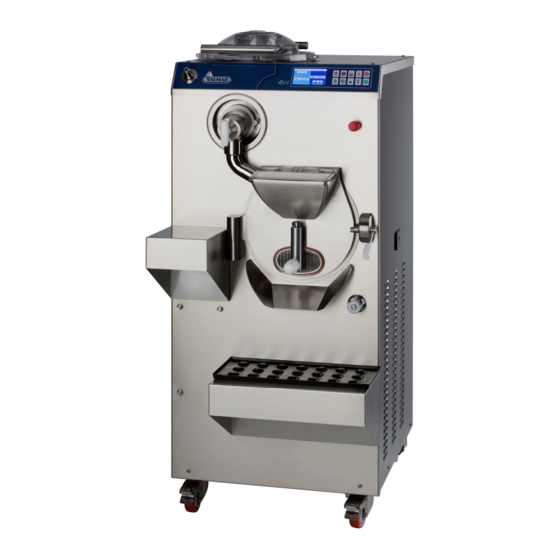
- Page 1 VALMAR HANDLING, OPERATING AND MAINTENANCE GUIDE OF THE APPLIANCES FOR THE PRODUCTION OF ICE CREAM Model MULTY P TTi Ver_MU_TT_001...
- Page 2 Italian Gelato Concepts Pty Limited PO Box 2134 Toowong Qld 4066 ABN 48 603 731 424 www.italiangelato.com.au info@italiangelato.com.au Mob: +61 (0) 411 089 142...
-
Page 3: Table Of Contents
TABLE OF CONTENTS INSTRUCTIONS ON HOW TO USE THE GUIDE ........7 SYMBOLS USED IN THE GUIDE ............7 GENERAL FEATURES AND SPECIFICATIONS ........8 GENERAL FEATURES ................ 8 IDENTIFICATION OF THE APPLIANCE ........... 10 TECHNICAL SPECIFICATIONS ............11 TRANSPORTATION AND PLACING OF THE APPLIANCE ....12 INSTRUCTIONS FOR PREVENTING INJURIES ...... -
Page 4: Table Of Contents
12.6 OUTLET HOLE COVER ..............103 12.7 TO-DO LIST BEFORE OPERATING THE APPLIANCE ....104 13 CLEANING OF THE APPLIANCE ............105 13.1 INSTRUCTIONS FOR THE PREVENTION OF INJURIES ....105 13.2 CLEANING THE SURFACES OF THE APPLIANCE ....... 106 13.3 USING THE WATER PIPE FOR CLEANING ........ - Page 5 BASIC STARTING OF THE MACHINE STARTING OF THE MACHINE (heating at 85° C ): • With quick key AUTOMATIC AUTOMATIC - button for the heating of the mixture up to 85° C. STARTING OF THE MACHINE (ice cream production) • With quick key ICE CREAM ICE CREAM - button for the producing of the ice cream in MODE 1.
- Page 6 PAY PARTICUAL ATTENTION - HOT MIXTURE! Duiring the heating operation (hot mixture) or after emptying of it (time 10 minutes) the user: can only by handle slowly opened or closed the outlet valve! can turn the handle in clockwise direction (for opening and closing the outlet pipe)! can’t apprehended or turn the inox part of the outlet pipe! The user must take particular attention when slow opening and closing the...
-
Page 7: Instructions On How To Use The Guide
1 INSTRUCTIONS ON HOW TO USE THE GUIDE Since we are in the company VALMAR aware that it is in yours as well as in our interest that the machine would operate at its best and as cheap as possible we have prepared this instruction manual, in order to assist you with your machine. -
Page 8: General Features And Specifications
The appliance is designed exclusively for the ice cream and other mass (custard...) production and the processing of fresh ice cream. The manufacturing company VALMAR cannot be held liable in any way for personal injuries or damage caused to the appliance in cases when the appliance has been used for any other purposes than those specified. - Page 9 Additional start-up and appliance's adjustments can be made on the client's premises by technicians authorized by VALMAR.Set the appliance in a suitable place, block it to ensure stability, and connect to the water and power supplies.
-
Page 10: Identification Of The Appliance
Caution must be taken because the outlet valve and the pipe are heated because they are exposed at hot mixture. Danger of scalding! mixing in the mixture treating cylinder (MIXING, CLEANING, DESINFECTING, TESTING START UP Cylinder - cooling part: mixing and cooling of the ice cream mixture in the production cylinder in trough the selected program (quick button) mixing and cooling of the cream mixture in the production cylinder in trough the selected program (START... -
Page 11: Technical Specifications
The ID label must not be removed or damaged! 2.3 TECHNICAL SPECIFICATIONS The appliances essential technical specifications: power supply voltage (see appliance label) maximum current (see appliance label) power (see appliance label) nominal frequency (see appliance label) water consumption production capacity capacity of a cylinder cycle weight dimensions... -
Page 12: Transportation And Placing Of The Appliance
Note that 1 liter of ice cream mixture is equivalent to 1,1 kilogram. The water consumption in cylinder depends on: the incoming water temperature, the ice cream mixture (type), the ice cream mixture temperature, the required final ice cream temperature. 3 TRANSPORTATION AND PLACING OF THE APPLIANCE 3.1 INSTRUCTIONS FOR PREVENTING INJURIES... -
Page 13: Unpacking Of The Appliance
Remove the hand lift from underneath and handle the crate with the forklift truck. Make sure that the weight is focused on the holding points. Remove the crate from the lorry with the forklift truck in reverse gear as soon as the crate is moved out of the lorry, and lower the crate to the minimal height of around 30 cm. -
Page 14: Requirements And Conditions For Normal Operation Of The Appliance
While placing the appliance in position, block the front wheels (by pressing the brake), which will ensure that the appliance will not be able to move. 4 REQUIREMENTS CONDITIONS NORMAL OPERATION OF THE APPLIANCE Before connecting the appliance to electricity supply, the operator must make sure that environment requirements have been met: the temperature and humidity of the air must be appropriate and the water supply and electricity networks comply with all requirements for normal operation of the appliance. -
Page 15: Electricity Supply Requirements
Prior to connecting the appliance to the power source, the temperature, pressure and water flow from the water supply network must be checked. Permitted water temperature and water pressure from the water supply network: min. max. WATER TEMPERATURE 5° C 30°... -
Page 16: Connecting The Appliance
The MAIN SWITCH must be installed in the immediate vicinity of the appliance, where it must be easily visible, accessible to the operator and appropriately marked. Magnetothermic differential FUSES (slot ≥ 3 mm) of appropriate dimensions must be installed between the electricity network and the MAIN SWITCH. model max. -
Page 17: Connecting The Appliance To The Power Supply
WATTER SUPPLY PORT (condenser) WATER OUTLET PORT (condenser) WATTER SUPPLY PORT (pipe – drinkable water) If the appliance is meant to be used in areas with two separate water supplies, two separate water connectors are built in it, one for each: a DRINKING WATER SUPPLY PORT and a COOLING WATER SUPPLY PORT (condenser). -
Page 18: Operating The Appliance
Connecting instructions for five-vein cable (three-phase appliances – 400/50/3): phase type color 400 V ~ black 400 V ~ brown 400 V ~ grey neutral blue ground yellow-green A test start-up of the appliance is carried out by an appropriately trained electrician who has also connected the machine so as to make sure that it is properly connected (see the section on MAINTENANCE). -
Page 19: Control Board
WATER PIPE CONTROL BOARD (DRINKABLE WATER) EMERGENCY STOP SWITCH WATER VALVE The control panel is used to: • display the status or the operation phase; • perform the settings; • to show messages and errors. The emergency stop switch is used to safely and securely switch of the electronics. - Page 20 7.1.1 TOUCH SCREEN OF THE KETTLE 7.1.1.1 TOUCH SCREEN (dual inactive home screen left - kettle part) DESCRIPTION: TUTOR MESSAGES help users giving them instructions and information about the processing. They also provide information on any errors and give warnings on operations.
- Page 21 DESCRIPTION: TUTOR MESSAGES help users giving them instructions and information about the processing. They also provide information on any errors and give warnings on operations. POSITION OF THE MACHINE (standby). Use this button to enter in the SETTING MENU QUICK PROGRMS KEYS. 7.1.1.3 Setting menu screen:...
- Page 22 PROGRAM MENU Use this function to enter MACHINE PARAMETERS Use this function to enter LANGUAGE SELECTION Function to be used only by Valmar technicians Use this function to enter in PASSWORD screen. Digit password to LOCK/UNLOCK the activities of the machine.
- Page 23 Press the HOME button to return to the dual inactive home screen. For technician - net connection. By correct code you can access to connection between touch screen and computer, TV… Use this function to enter in PASSWORD screen. Digit password to RESET factory settings (cancel all changes).
- Page 24 Number of the software. Version – number of the firmware (relay board). Total hours of the working. Total hours of the standbay. Press BACK to return to the previous screen. Press HOME to return to the main screen. 7.1.1.5 Setting screen: DESCRIPTION: Year setting.
- Page 25 Beep volume setting. Button volume setting. Press BACK to return to the previous page. Press HOME to return to the dual inactive home screen. Water flow calibration (only sweety machine). Celsius/Fahrenheit temperature setting. Save new settings. DOWN BUTTON decreased the actual value. ACTUAL VALUES.
- Page 26 Press the button. Set the current month on the display by using the arrows. Confirm with the button. Factory default – central European time zone Press the button. Set the current day on the display by using the arrows. Confirm with the button.
- Page 27 Press the button. Select Celsius or Fahrenheit as unit of measurement by using arrows. Confirm with the button. Factory default – Celsius. Press the button. Adjust the volume of the signal by using the arrows. Confirm with the button. Factory default – value 100. Press the button.
- Page 28 SORBET, SLUSH, FRUIT SAUCE AND TOPPING PROGRAM MENU Select the FRUIT button to enter the list of programs for fruit sorbets, slush and sugar syrups. PROGRAM MENU FOR CHOCOLATE ICE CREAM AND OTHER CHOCOLATE PRODUCTS Select the CHOCO button to enter the list of programs for chocolate ice cream, toppings, sauces, ganache, creams, etc..
- Page 29 Button UP to scroll the program list. Button DOWN to scroll the program list. NOT ACTIVE Press the button to enter the step settings screen. NOT ACTIVE To be used only by Valmar technicians. Press here to have a short program description.
- Page 30 Press CHANGE to set the program and link it with one of the four hot start buttons on the push-button panel and on the main display. Press BACK to return to the previous screen. Press HOME to return to the dual inactive home screen.. 7.1.1.7 Program list tekst screen: Program description text Cursor UP and DOWN.
- Page 31 7.1.1.8 Active program screen: DESCRIPTION: PLUS button. Select this button to enter in additional display. PROGRAM NUMBER. SET button. Select this button to enter in programs parameters of current step. PROGRAM NAME. TUTOR MESSAGES help users giving them instructions and information about the processing. They also provide information on any errors and give warnings on operations.
- Page 32 BUTTON ROCKET increased the actual speed. If the button is grey the increasing is not possible. PRODUCTION MODE DISPLAY. TIME DISPLAY. If the operator not operating (push) on active program screen machine after a few seconds change it with the active single home screen: For returned on active program screen click anywhere on the single active home screen.
- Page 33 PROGRAM NUMBER. PROGRAM NAME. Press the button to enter the parameters screen (only for Valmar technicians). Press BACK to return to the previous screen. Press HOME to return to the dual inactive home screen.. Press info to have a short program description.
- Page 34 TUTOR MESSAGES help users giving them instructions and information about the processing. They also provide information on any errors and give warnings on operations. UP BUTTON increased the actual value. If the button is grey the increasing is not allowed. TEMPERATURE DISPLAY –...
- Page 35 7.1.2.2 Inactive home screen: DESCRIPTION: TUTOR MESSAGES help users giving them instructions and information about the processing. They also provide information on any errors and give warnings on operations. POSITION OF THE MACHINE (standby). Use this button to enter in the SETTINGS MENU QUICK PROGRMS KEYS.
- Page 36 PROGRAM MENU Use this function to enter MACHINE PARAMETERS Use this function to enter LANGUAGE SELECTION Function to be used only by Valmar technicians Use this function to enter in PASSWORD screen. Digit password to LOCK/UNLOCK the activities of the machine.
- Page 37 Press the HOME button to return to the dual inactive home screen. For technician - net connection. By correct code you can access to connection between touch screen and computer, TV… Use this function to enter in PASSWORD screen. Digit password to RESET factory settings (cancel all changes).
- Page 38 Total hours of the working. Total hours of the standbay. Press BACK to return to the previous screen. Press HOME to return to the main screen. 7.1.2.5 Setting screen: DESCRIPTION: Year setting. Time setting. Month setting. Minutes setting. Day setting. Liter/Gallon setting.
- Page 39 Press BACK to return to the previous page. Press HOME to return to the dual inactive home screen. Water flow calibration (only sweety machine). Celsius/Fahrenheit temperature setting. Save new settings. DOWN BUTTON decreased the actual value. ACTUAL VALUES. UP BUTTON increased the actual value. In the SETTINGS screen you can set the following parameters: 1.
- Page 40 Press the button. Set the current day on the display by using the arrows. Confirm with the button. Factory default – central European time zone. Press to activate the hour button. Set the hour on the display by using arrows. Confirm with the button.
- Page 41 Press the button. Adjust the volume of the signal by using the arrows. Confirm with the button. Factory default – value 100. Press the button. Adjust the volume of the button by using the arrows. Confirm with the button. Factory default – value 70. 7.1.2.6 Program menu screen: DESCRIPTION: ICE CREAM PROGRAM MENU...
- Page 42 PROGRAM MENU FOR CHOCOLATE ICE CREAM AND OTHER CHOCOLATE PRODUCTS Select the CHOCO button to enter the list of programs for chocolate ice cream, toppings, sauces, ganache, creams, etc.. CUSTOMIZED PROGRAM MENU FOR ICE CREAM, SORBETS, PASTRY AND GASTRONOMY PRODUCTS Select the CUSTOM button to enter the list of customizable programs and programs for ice cream production in mode 2, mode 3 and mode 4.
- Page 43 Button UP to scroll the program list ist. Button DOWN to scroll the program list. NOT ACTIVE Press the button to enter the step settings screen. NOT ACTIVE To be used only by Valmar technicians. Press here to have a short program description.
- Page 44 Press CHANGE to set the program and link it with one of the four hot start buttons on the push-button panel and on the main display. Press BACK to return to the previous screen. Press HOME to return to the dual inactive home screen. 7.1.2.8 Program list tekst screen: Program description text Cursor UP and DOWN.
- Page 45 7.1.2.9 Active program screen: DESCRIPTION: SECOND DEDICATED button. Select this button to activate the alternative extraction arising from actual program (not alyaws present). PROGRAM NUMBER. SET button. Select this button to enter in programs parameters of current step. PROGRAM NAME. TUTOR MESSAGES help users giving them instructions and information about the processing.
- Page 46 MIXER SPEED DISPLAY. BUTTON ROCKET increased the actual speed. If the button is grey the increasing is not allowed. DISPLAY – production mode of ice cream. DISPLAY –cooling at temperature DISPLAY – maintenance time TIME DISPLAY. PLUS button. Select this button to enter in additional display.
- Page 47 DESCRIPTION: TUTOR MESSAGES help users giving them instructions and information about the processing. They also provide information on any errors and give warnings on operations. UP BUTTON increased the actual value. If the button is grey the increasing is not allowed. ACTUAL VALUES.
- Page 48 PROGRAM NUMBER. PROGRAM NAME. Press the button to enter the parameters screen (only for Valmar technicians). SET button. Select this button to enter in programs parameters of current step. Press BACK to return to the previous screen.
-
Page 49: Push-Button Panel (Treating – Heating)
7.2 PUSH-BUTTON PANEL (TREATING – HEATING) 7.2.1 KEYS (kettle - heating part) 7.2.1.1 key START 7.2.1.1.1 START with the START CYCLE BUTTON on the PUSH-BUTTON PANEL The START CYCLE button is always set to one of the menu programs (except when first using the machine). 1. - Page 50 2. Select one of the icons representing the various menus to enter the list of available programs. 3. Use the UP / DOWN arrows to scroll the list of available programs. Select the desired program by pressing the relevant button (e.g. 29). When pressed, the button changes color and becomes black.
- Page 51 1. Press the button to connect the machine to the set program (cooling). 2. Press the button to start the set program (cooling). 7.2.1.3 key MIXING The MIXING button activates the mixing into the kettle. The heating cycle will be stopped automaically. In inverter machine the set speed of the mixing is speed 5 which you can change(+- 2 speeds).
- Page 52 The HALF-KETTLE HEATING button activates the heating only with heater which is positionated in the lower part of the kettle. The button can be switched on during the heating cycle and is active only during the running program. The function cannot be stored. Press the button to start a half heating (lower) of the kettle.
-
Page 53: Push-Button Panel (Production – Cooling)
7.3 PUSH-BUTTON PANEL (PRODUCTION – COOLING) 7.3.1 KEYS (cylinder – cooling part) 7.3.1.1 key START 7.3.1.1.1 START with the START CYCLE BUTTON on the PUSH-BUTTON PANEL The START CYCLE button is always set to one of the menu programs (except when first using the machine). 1. - Page 54 7.3.1.1.2 START with the START CYCLE BUTTON from the MENU 1. Press the button to display the set NEW program or the LAST program used. 2. Select one of the icons representing the various menus to enter the list of available programs.
- Page 55 Press the button to start a low continuos mixing. 1. The machine starts with speed 5 for 480 seconds. With STOP button you can stop mixing – extraction (in any phase). 7.3.1.3 Key STANDARD EXTRACTION (normal speed) The STANDARD EXTRACTION button activated the automatic variable speed mixing.
- Page 56 7.3.1.4 Key STANDARD EXTRACTION (low speed) - from the MENU The STANDARD EXTRACTION button activated the automatic variable speed mixing. Mixer speed will gradually increase until full ice cream extraction. 1. In running program press the button start automatic variable speed mixing. 2.
- Page 57 The EXTRACTION FOR MAXIMUM QUANTITY of VARIEGATED ICE CREAM button activated the mixing which will gradually increase until full ice cream extraction. The program consists of 11 steps alternating mixer speed, from 6/7/8 (quick) to 2 (slow). 1. In running program press the button start extractionwith alternating mixing speed.
- Page 58 7. Now the machine works with speed 2. For continue press START CYCLE button. 8. Now the machine works with speed 8. For continue press START CYCLE button. 9. Now the machine works with speed 2. For continue press START CYCLE button.
- Page 59 7.3.1.6 START with the EXTRACTION OF CREAM AND OTHER THICK PRODUCT BUTTON from the MENU The EXTRACTION OF CREAM AND OTHER THICK PRODUCT button activated a low speed extraction for creams, thick products and products requiring low speed extraction. 1. In running program press the button start low mixing speed.
- Page 60 1. In running extraction step press the button to start cooling. 2. The machine starts compressor for 10 seconds. On the thouch screen (cylinder – right side) in tutor message show caption Ur-FORCE_COMPRESSOR (switching of the cooling for 10 seconds)… After 10 seconds the machine automatically switches off the compressor.
-
Page 61: First Using Of The Machine
At the first using is necessary to select the language. If the language is not selected machine after 30 seconds chooses English language. 1. Wait for the software to upload. 2. After Valmar screens, the LANGUAGE SELECTION screen is automatically displayed. -
Page 62: Language Selection
6. First carefully read the text and then press the confirm button to confirm the language chosen. The dual inactive home screen is displayed. 7. The machine is ready for use with instructions in the selected language. 7.5 LANGUAGE SELECTION The machine provides instructions in the user’s language for easier use. -
Page 63: Data Download
7.6 DATA DOWNLOAD 7.6.1 DATA DOWNLOAD with a USB key (cooking part) 7.6.1.1 Data download for analisis – protected files (sending to VALMAR GLOBAL!) 1. Press the right part (colling) on the dual inactive HOME screen to enter in the single inactive home screen. - Page 64 9. When the download is complete appears on the message bar message DOWNLOAD OK. Pull out the USB key and send data to VALMAR GLOBAL company. 7.6.1.2 Data download of the ERRORS 1. Press the right part (colling) on the dual inactive HOME screen to enter in the single inactive home screen.
- Page 65 2. On the single inactive home screen press the TOOLS button to enter in SETTING menu. 3. Press the PARAMETERS button enter the PARAMETERS screen. 4. Insert the USB key into the relevant USB port. 5. Press ERROR button to enter in the ERROR screen.
- Page 66 8. On the message bar appears message DOWNLOAD. 9. When the download is complete appears on the message bar message DOWNLOAD OK. Pull out the USB key. Data from USB key (file type: xml) you can open on computer with xml viewer (Excel, Libre Ofice Calc, Browser, text editor...).
- Page 67 Libre Ofice Calc, Browser, text editor...) 7.6.2 DATA DOWNLOAD with a USB key (cooling part) 7.6.2.1 Data download for analisis – protected files (sending to VALMAR GLOBAL!) 1. Press the right part (colling) on the dual inactive HOME screen to enter in the single inactive home screen.
- Page 68 8. On the message bar appears message DOWNLOAD. 9. When the download is complete appears on the message bar message DOWNLOAD OK. Pull out the USB key and send data to VALMAR GLOBAL company.
- Page 69 7.6.2.2 Data download of the ERRORS 1. Press the right part (colling) on the dual inactive HOME screen to enter in the single inactive home screen. 2. On the single inactive home screen press the TOOLS button to enter in SETTING menu.
- Page 70 7. Press USB button to download errors into the USB key. 8. On the message bar appears message DOWNLOAD. 9. When the download is complete appears on the message bar message DOWNLOAD OK. Pull out the USB key. Data from USB key (file type: xml) you can open on computer with xml viewer (Excel, Libre Ofice Calc, Browser, text editor...) 7.6.2.3 OPTION (surcharge) - download data of the machine, cycle (customer)
-
Page 71: Update Of New Program Or New Database
4. Insert the USB key into the relevant USB port. 5. Press “HCCP” button to enter in “HCCP” screen. 6. Press USB button to download “HCCP” data into the USB key. 7. On the message bar appears message DOWNLOAD. 10. When the download is complete appears on the message bar message DOWNLOAD OK. -
Page 72: Wear Of The Scrapers
3. New data is uploaded automatically. After upload, the uploaded program and software version and the date of the last update are displayed. Automatic switch to the type and model screen. The screen shows the machine type and model. Then the notice - confirm screen is displayed 4. -
Page 73: Programs
For all damage on the machine or to a person which derived from inconsediration of this message the company Valmar Global is not responsible! It is necessary to keep record on the working hours of the mixer scrapers (see the chapter 14.5 and write hours down to appendix A)! -
Page 74: Menu Programs
9 MENU PROGRAMS 9.1 MENU PROGRAMS of the HEATING PART 9.1.1 HOW ACCESS TO THE PROGRAM MENU 1. Press the left part on the dual inactive HOME page (kettle) to enter in the single inactive home screen. 2. On the single inactive home screen press the TOOLS button to enter in SETTINGS screen. - Page 75 5. Use the UP / DOWN arrows to scroll the list of available programs. Select the desired program by pressing the relevant button (e.g. 26). When pressed, the button changes color and becomes black. 6. Press the PROG i button to enter the INFO screen with a description of the selected program.
- Page 76 9.1.2.2 STARTING OF THE PROGRAMS with SHORTCUT START CYCLE button You can enter the program menu by pressing the START CYCLE button 2. When the machine is in home screen press button to enter the program menu. 3. Select one of the icons representing the various menus to enter the list of available programs.
- Page 77 1. Press the left part (kettle) on the dual inactive HOME page to enter in the single inactive home screen. 2. On the single inactive home screen press the TOOLS button to enter in SETTINGS screen. 3. Press the PROGRAMS button enter the PROGRAM MENU.
- Page 78 7. Press the shortcut button (e.g. ) to be linked to the selected program. 8. Press the OK button to confirm the changing. Single inactive home screen with changed preset program - from 25 to 27. Press the BACK button to return to the previous screen.
- Page 79 In the most programs the permeted changing of the speed is saved. See the relevant program info to check whether changes are stored. If changes are NOT stored they will be valid only for the running program! The new parameter is valid and used during the running program and will be valid and used when running the program in future.
-
Page 80: Menu Programs Of The Cooling Part
If the DOWN button is grey the decreasing of the maintenance time is not allowed. In the most programs the permeted changing of the maintenance time is saved. See the relevant program info to check whether changes are stored. If changes are NOT stored they will be valid only for the running program! The new parameter is valid and used during the running program and will be valid and used when running the program in future. - Page 81 menus (e.g. ) to enter the list of available. 5. Use the UP / DOWN arrows to scroll the list of available programs. Select the desired program by pressing the relevant button (e.g. 01). When pressed, the button changes color and becomes black. 6.
- Page 82 9.2.2.2 STARTING OF THE PROGRAMS with SHORTCUT START CYCLE button You can enter the program menu by pressing the START CYCLE button 1. When the machine is in dual inactive home screen press the button to enter the program menu. 2.
- Page 83 9.2.3.1.1 CHANGING OF THE QUICK KEYS Single inactive home screen with factory preset programs. 1. Press the right part (cylinder) on the dual inactive HOME screen to enter in the single inactive home screen. 2. On the single inactive home screen press the TOOLS button to enter in SETTINGS screen.
- Page 84 6. After selecting the program, press the CHANGE button to enter the following. 7. Press the shortcut button (e.g. ) to be linked to the selected program. 8. First carefully read the text and then press the OK button to confirm the changing. Single inactive menu screen with changed preset program -...
- Page 85 3. Modify parameters with the buttons. 4. Press OK button to confirem the value. If the confirm button is grey this mean that the possibility of the changing for this parameter is disabled. 5. Press the BACK button to return to the previous screen.
- Page 86 In the most programs the permeted changing of the speed is saved. See the relevant program info to check whether changes are stored. If changes are NOT stored they will be valid only for the running program! The new parameter is valid and used during the running program and will be valid and used when running the program in future.
-
Page 87: Changing Parameters Of Machine
If the DOWN button is grey the decreasing of the maintenance time is not allowed. In the most programs the permeted changing of the maintenance time is saved. See the relevant program info to check whether changes are stored. If changes are NOT stored they will be valid only for the running program! The new parameter is valid and used during the running program and will be valid and used when running the program in future. - Page 88 5. Press the confirem or enter button. 6. Wait for the software to upload. 7. After Valmar screens, the LANGUAGE SELECTION screen is automatically displayed. 8. Select the desired language. If it is not on the screen, press the button to enter language selection screen 2.
- Page 89 11. First carefully read the text and then press the confirm button to confirm the language chosen. The HOME screen is displayed. 12. The machine is ready for use with instructions in the selected language. 10.1.2 LOCK/UNLOCK THE ACCESS OF OPERATION 10.1.2.1 LOCK the access of operation on the machine The user can lock access of operation on the machine.
- Page 90 4. Enter the password - user code 000000. 5. Press the confirem or enter button to lock the access to operation on the machine. 6. On display appears the dual inactive Home page. 10.1.2.2 UNLOCK the access of operation on the machine 10.1.2.2.1 Unlock the access of operation on the machine (until such time as the power supply of the machine is not excluded) The user can unlock the access of operation for period in which the power...
- Page 91 3. Enter the password - user code 000000. 4. Press the confirem or enter button to unlock the access to operation on the machine (only for time when the machine have power source). 5. On display appears the single inactive home screen.
- Page 92 3. Enter the password - user code 000000. 4. Press the confirem or enter button to unlock the access to operation on the machine (only when the machine have power source. 5. On the single inactive home screen press the TOOLS button to enter in SETTINGS screen.
-
Page 93: Changing Parameters (Cooling Part)
9. On display appears the dual inactive Home page. Press the BACK button to return to the previous screen. Press the HOME button to cancel the operation and return to the dual inactive HOME screen. 10.2 CHANGING PARAMETERS (cooling part) 10.2.1 RESET TO THE FACTORY SETTING The user can restore all the programs, all changes are lost. - Page 94 5. Press the confirem or enter button. 6. Wait for the software to upload. 7. First carefully read the text and then press the confirm button to confirm the language chosen. The HOME screen is displayed. 8. The machine is ready for use with instructions in the selected language.
- Page 95 2. On the single inactive home screen press the TOOLS button to enter in SETTINGS screen. 3. Press the CODE button to enter in the PASSWORD screen. 4. Enter the password - user code 000000. 5. Press the confirem or enter button to lock the access to operation on the machine.
- Page 96 1. Press the left part on the dual inactive HOME page (kettle) to enter in the single inactive home screen. 2. On the single inactive home screen press the LOCK button to enter in the PASSWORD screen. 3. Enter the password - user code 000000. 4.
- Page 97 10.2.2.2.2 Unlock the access of operation on the machine (permanently) The user can permanently unlock access of operation on the machine. 1. Press the left part on the dual inactive HOME page (kettle) to enter in the single inactive home screen. 2.
- Page 98 7. Enter the password - user code 000000. 8. Press the confirem or enter button to lock the access to operation on the machine. 10. On display appears the dual inactive Home page. The machine is permanently unlocked and you can work normally. Press the BACK button to return to the previous screen.
-
Page 99: Protection Of The User And Of The Machine
11 PROTECTION OF THE USER AND OF THE MACHINE 11.1 PROTECTION OF THE USER A safety switch, which is built into the machine under the rim of the mixture treating cylinder, protects the operator against injuries that might be caused by the mixer’s rotation. -
Page 100: Use Of The Appliance
12 USE OF THE APPLIANCE 12.1 INSTRUCTIONS FOR THE PREVENTION OF INJURIES Only authorized persons, who know how the machine is operated, must be allowed to handle it. Operators must be familiar with all regulations concerning occupational safety and fire safety measures, and they must know where fire extinguishers are located. -
Page 101: Basic Rules For Operating The Appliance
12.2 BASIC RULES FOR OPERATING THE APPLIANCE The user operates the appliance standing in front of appliance. The appliance must be always under users control during operation. Only a single operator can use the appliance at the time. The simultaneously use of the appliance from multiple users is forbidden. KETTLE COVER HANDLE OF COVER WATER PIPE... -
Page 102: Cover Of The Kettle
12.3 COVER OF THE KETTLE Gripping it firmly with hand by the lever lifting it back to the open position opens the kettle cover. If the machine is in the mixing phase, lifting the cover will terminate mixing. In order to close the cover grip it always at the cover lever and lower it in close position. -
Page 103: Processing Cylinder Door
12.5 PROCESSING CYLINDER DOOR Lifting the handle over the taper and shifting it to the right release the processing cylinder door. The door can now be opened. Closing the door and pressing the handle over the taper down, thereby preventing it from opening automatically, close the processing cylinder door. LOCKING SCREW 12.6 OUTLET HOLE COVER Loosening (in counter-clockwise direction) the locking screw opens the ice... -
Page 104: To-Do List Before Operating The Appliance
The cover of the ejection opening closes by turning the handle in the counter clockwise direction. LIMITER 12.7 TO-DO LIST BEFORE OPERATING THE APPLIANCE Before each use of the appliance: make sure that the floor around the machine is not slippery or wet; make sure that the water supply valve is open;... -
Page 105: Cleaning Of The Appliance
13 CLEANING OF THE APPLIANCE 13.1 INSTRUCTIONS FOR THE PREVENTION OF INJURIES Only authorized persons, who know how the machine is operated, must be allowed to clean it. Operators must be familiar with all regulations concerning occupational safety and fire safety measures, and they must know where fire extinguishers are located. -
Page 106: Cleaning The Surfaces Of The Appliance
Every day before using the appliance, the correct functioning of the safety switch on the kettle cover and door must be checked. When the appliance is in mixing - both parts (press the button, press the button) phase open - rise the kettle cover and remove the net of the batch feeder. -
Page 107: Cleaning Of Parts That Come In Contact With The Ice Cream
13.4 CLEANING OF PARTS THAT COME IN CONTACT WITH THE ICE CREAM All parts, which come into contact with ice cream mixture, must be cleaned before and after every use. With regular cleaning practice you comply with standards of hygiene and ensure ice cream mixture treating quality. 13.4.1 CLEANING OF CYLINDER (COOKING) Cleaning process: make sure that the mixture treating control panel is in STOP state;... - Page 108 Lift the cover lever and remove the lower part of the cylinder cover. unscrew (in counter-clockwise direction) the plastic nut from the mixer. MIXER slowly and consistently pull the mixer (cooking part) out of the cylinder; exercise great care to prevent accidental dropping and consequent damaging of the mixer;...
- Page 109 place the mixer on solid surface and remove each slider from the mixer individually (push the slider downwards until it jumps off the shaft); slowly and consistently pull the blockader out of the cylinder; exercise great care to prevent accidental dropping and consequent damaging of the blockader;...
- Page 110 Open the batch feeder cover. Remove the batch feeder cover with net. disassemble the outlet pipe (complete set) of the ejection opening: Rotate (in counter-clockwise direction) the outlet pipe.
- Page 111 Rotate (in counter-clockwise direction) the lower part of the outlet pipe. Pull out the lower part of the outlet pipe from the pipe. Rotate (in counter-clockwise direction) the outlet pipe into the right position.
- Page 112 Remove – pull out from the housing (kettle) the outlet pipe. Rotate (in clockwise direction) the tube into the right position. Remove the tube from the outelt pipe. Turn the handle (in counter-clockwise direction) and remove it.
- Page 113 Remove –pul out the piston from the housing of the outelt pipe. remove and inspect all seals. If the seals are cracked, worn or has lost elasticity, it must be replaced with a new one; all removed parts and kettle must be cleaned in a mixture of water and disinfection agent.
- Page 114 Screw (in clockwise direction) the handle on to the piston. Insert the tube into the outlet pipe. Rotate (in counter-clockwise direction) the tube into the right position. Push the handle into the housing of the outlet pipe.
- Page 115 Insert the outlet pipe on to the housing (kettle). Rotate (in clockwise direction) the outlet pipe. Insert the lower part of the outlet pipe on to the pipe. Rotate (in clockwise direction) the lower part of the outlet pipe.
- Page 116 Rotate (in clockwise direction) the outlet pipe to final position. Insert the batch feeder cover with net. Close the batch feeder cover. slowly and carefully place the blockader into the kettle.
- Page 117 Place the mixer on solid surface and place each scraper back onto the mixer individually: Hold the scraper with both hands and place the each scraper to the scraper holder and by pressing it towards the spade (compressing the spring) the scraper is placed on the shaft.
- Page 118 screw (in clockwise direction) the plastic nut on the mixer shaft. assemble the quick cover of the kettle (set of parts): Place the cover with screw ( ) to top side and lower the handle. code 10222030 Put the disc ( ) and screw it (in clockwise direction) to the lower code 10222031 part of the cover.
- Page 119 Put the tap ( ) and screw it (in clockwise direction) to the disc. code 10222032 The cylinder cover is now fully assembled and positioned. 13.4.2 CLEANING OF CYLINDER (ICE CREAM ) Cleaning process: make sure that the mixture treating control panel is in STOP state; make sure that the ejection opening is well closed;...
- Page 120 remove the batch feeder cover lid and the safety net from the cylinder doors; place the batch feeder cover lid and the safety net on solid surface and remove batch feeder cover lid from safety net; With both hands graps and then push – rotate chute (in counter- clockwise direction) for remove it .
- Page 121 Unscrew the (in counter-clockwise direction). LOCK NUT All components pull out. Exercise great care to prevent accidental dropping and consequent damaging of parties. disassemble all components ejection opening: Remove the cover from the crossbar. Unscrew the locking screw (in counter-clockwise direction) from the crossbar.
- Page 122 Remove the rubber seal from the cover. open the door and take off: Slowly and carefully with both hands pull the door out of the hinges; exercise great care to prevent accidental dropping and consequent damaging of the door.
- Page 123 place the door on solid surface and remove the rubber seal from the door; slowly and carefully with both hands pull the mixer out of the cylinder; exercise great care to prevent accidental dropping and consequent damaging of the mixer; place the mixer on solid surface and remove each scraper from the mixer individually (push the scraper downwards until it jumps off the shaft);...
- Page 124 after that each scraper must be very carefully inspected (checked the state of the spring too); remove the shaft sealing from the mixer (in the case, the shaft sealing is cracked, worn or inelastic it has to be replaced by a new seal); if you notice drops of ice cream mixture in the catcher, the shaft seal must be replaced with a new one;...
- Page 125 instructions of the disinfection agent manufacturer as well as hygienic standards, which are valid in your country. It is strictly forbidden to put plastic parts of the appliance into the dishwasher to clean them! it is recommended that all seals and chute are greased with sanitary use Vaseline;...
- Page 126 The scraper must lock onto the shaft. Please check, whether the scraper is firmly attached to the shaft and whether it is placed correctly. It is strictly forbidden to put plastic parts (scrapers) of the appliance into the dishwasher to clean them! Incorrectly and correctly attached scraper: insert the mixer into the cylinder: Hold the mixer with both hands and place it very slowly into the cylinder.
- Page 127 placing the door into the hinges: Slowly and carefully with both hands placing the door into the hingesand and close them. Exercise great care to prevent accidental dropping and consequent damaging of the door. Every time is necessary a upper edge of the chute grased with sanitary Vaseline.
- Page 128 assembly all components (cover, crossbar,lock nut…): Screw the locking screw (in clockwise direction) into the crossbar. Place the rubber seal into the cover. Fit the cover on the crossbar.
- Page 129 all parts place into the housing holder: Slowly and carefully with both hands push parts into housing holder exercise great care to prevent accidental dropping and consequent damaging of the parties. Screw the (in clockwise direction). LOCK NUT placing the batch feeder cover lid into the safety net;...
-
Page 130: Disinfection Of The Kettle
placing the batch feeder cover lid with safety net into the batch feeder Close the batch feeder cover. 13.5 DISINFECTION OF THE KETTLE Desinfections process: make sure that the mixture treating control panel is in STOP state; make sure that the outlet valve is properly set and well closed; fill to the top of the kettle the disinfections mixture and close the cover lid;... -
Page 131: Disinfection Of The Ice Cream Production Cylinder
13.6 DISINFECTION OF THE ICE CREAM PRODUCTION CYLINDER Disinfections process: make sure that the production control panel is in STOP state; make sure that the cylinder door and the outlet hole cover are properly set and well closed; open the cylinder cover; fill the cylinder with a disinfecting mixture (is not necessary fill to the top);... -
Page 132: Problems, Errors And Troubleshooting
HOT AREA! 14.2 PROBLEMS, ERRORS AND TROUBLESHOOTING Malfunctions and errors are caused mostly by incorrect use, improper or inadequate maintenance or incorrect connection of the appliance. Therefore the operators must always carefully follow the instructions. The errors, the causes and troubleshooting: Error Cause Troubleshooting... -
Page 133: Regular Maintenance Inspection Plan
600 working hours Lubrication of bearings Cooling gas check VALMAR Company. 14.4 TEST RUN Procedure of the test run: make sure that the mixture treating control panel is in STOP state; make sure that the ejection opening is well closed;... - Page 134 The user of the machine must replace all of the mixer scrapers if: any of the scrapers is crumbled or deformed; any of the scrapers has a deformed spring; the wear of any scraper is uneven; the wear of any scraper deviates from the wear of other scrapers. Disregarding the condition or wear of the scrapers, the user of the machine should replace all of the scrapers after, at most, 600 hours of operation, or at least once a year.
-
Page 135: Replacing The Mixer Scrapers And Sliders
14.6 REPLACING THE MIXER SCRAPERS AND SLIDERS At each change of scrapers is also necessary to replace the sliders! At any change you must change all scrapers and all sliders (never only one or two,...). The mixer scrapers and sliders replacing process: make sure that the preparation and making control panels are in the STOP position;... - Page 136 remove each scraper from the mixer individually (push the scraper downwards until it jumps off the shaft); Install new scraper on the mixer: Hold the scraper with both hands and place the scraper to the holder and by pressing it towards the spade (compressing the spring) the scraper is placed on the shaft.
-
Page 137: Setting The Water Regulation Valve
Place the slider into the mixer; insert the mixer into the cylinder: Hold the mixer with both hands and place it very slowly into the cylinder. Place the mixer by the edge of the cylinder so that the spade which has the slider closest to the bottom of the cylinder is placed horizontally downwards, Slowly, without spinning, push the thusly placed mixer towards the end of the cylinder. -
Page 138: Danger Of Temperatures Below 0 ° C
14.8 DANGER OF TEMPERATURES BELOW 0 ° C Do not leave the appliance in an environment colder than 0ºC (273K). If this is the case, discharge water from the condenser. In order to empty the water out of the appliance, unscrew the cap of the safety valve (in counter clockwise direction). -
Page 139: Ordering Spare Parts
Finally, reattach the cap of the safety valve and screw it tight (in clockwise direction). 14.9 ORDERING SPARE PARTS The order for any spare part must include: model of the appliance, factory code (if possible,) serial number of the appliance, quantity;... - Page 140 Appendix A Date Working hours Date Working hours Date Working hours ALL WORKING HOURS...
- Page 141 Date Working hours Date Working hours Date Working hours ALL WORKING HOURS...
Need help?
Do you have a question about the MULTY P TTi Series and is the answer not in the manual?
Questions and answers