Table of Contents
Advertisement
Quick Links
Advertisement
Table of Contents

Related Manuals for Key-Disp KD21C


Summary of Contents for Key-Disp KD21C
-
Page 2: Table Of Contents
Content Product name and model ................1 Specifications ....................1 Appearance and Size ..................1 ◆Color categories .................. 1 Function Summary and Button Definition ............1 ◆Function Summary................1 ◆Functional Area Distribution ............... 2 ◆Button Definition ................2 General Operation ..................3 ◆Switching the eBike System On/Off ............. - Page 3 Assistance Level option ..............9 PAS Ratio Settings ................10 ◆Controller Over-Current Cut Settings ..........10 ◆Power Assistant Sensor Settings............10 The Direction of Power Assistant Sensor Settings ......10 The Sensitivity of PAS Settings ............11 Magnet quantity Settings ............... 11 ◆Speed Sensor option ................
-
Page 4: Product Name And Model
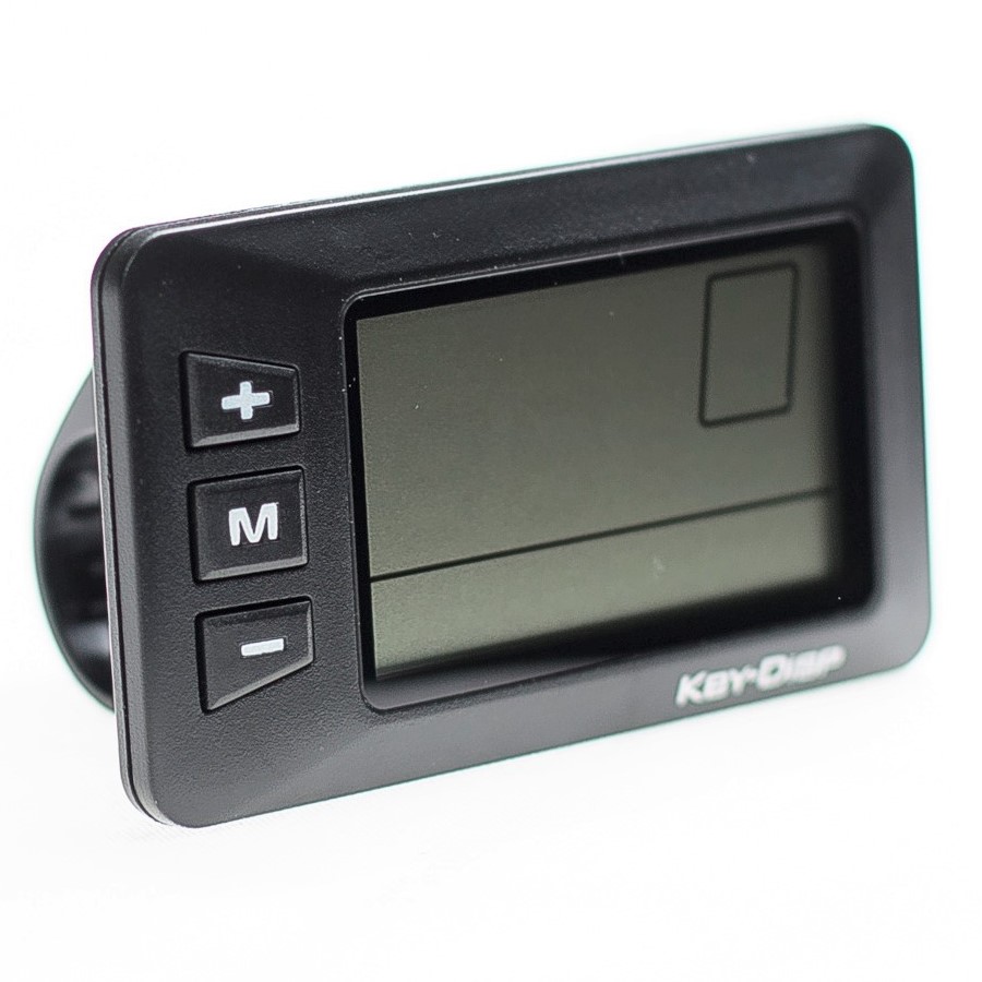
Top shell of the display is two color options, black and white, and bottom shell of the display is only one black. Function Summary and Button Definition ◆Function Summary KD21C can provide a lot of functions to fit the users’ needs. The... -
Page 5: Functional Area Distribution
●Recover Default Settings ◆Functional Area Distribution ◆Button Definition There are three buttons ( ) on the KD21C display that represented by the following functions respectively: MODE, UP, DOWN. -
Page 6: General Operation
General Operation ◆Switching the eBike System On/Off To switch on the eBike system, hold the MODE button for 2s. In the same way to hold the MODE button for 2s again, the eBike system will be switched off. When switching off the eBike system the leakage current is less than 1 uA. -
Page 7: Switching The Lighting On/Off
Push-assistance Mode ■ Push-assistance function may only be used when pushing the eBike. Danger of injury when the wheels of the eBike do not have ground contact while using the push-assistance function. ◆Switching the Lighting On/Off To switch on the display backlight and headlight of the eBike, hold the UP button for 2s. -
Page 8: Battery Indicator
Assistance Level “3” ◆Battery Indicator The five battery bars represent the capacity of the battery. W hen the battery is in low voltage, battery frame will flash to notice that the battery needs to be recharged immediately. Low Voltage Flash Battery Indicator ◆Error Code Indication If there are errors about the electronic control system, the error code... -
Page 9: Trip Distance Clearance
menu, hold both the UP and DOWN button for 2s. ■ All the Settings are operated in the case of parking the eBike. ◆Trip Distance Clearance TC represents trip distance clearance setting. To clear trip distance, press the UP/DOWN button to choose Y or N. The default value is N. -
Page 10: General Parameter Settings
value is “2”. To convert unit, press the UP/DOWN button to increase or decrease until the desired setting is displayed. To store a changed setting, press the MODE button, and then access trip distance clearance settings. To store a changed setting, hold the MODE button for 2s and then exit general settings. -
Page 11: Personalized Parameter Settings
faster than limit speed, the eBike system will switch off automatically. Limit speed ranges from 12Km/h to 40Km/h. The default value is 25Km/h. To change basic settings, press the UP/DOWN button to increase or decrease until the desired value is displayed. To store a changed setting and exit General Parameter Settings, hold the MODE button for 2s. -
Page 12: Battery Power Bar Settings
◆Battery Power Bar Settings VOL represents voltage settings. Each bar represents a voltage value. 5 bars voltage values must be entered one by one. For example, VOL 1 is first bar voltage value, the default value is 31.5. To set battery power bar, press the UP/DOWN button to increase or decrease the number. -
Page 13: Pas Ratio Settings
PAS Ratio Settings To modify the value of PAS ratio can match the different requirements. For example, the range is “45-55 percent” of “1” level, bottom value can be modified, and the default value is 50 percent. To store the modified setting, press the MODE button and turn to the next PAS ratio settings. -
Page 14: The Sensitivity Of Pas Settings
To change The Direction of Power Assistant Sensor Settings, press the UP/DOWN button to select F or b. To store a changed setting, press the MODE button and then access settings mode of PAS sensitivity. Direction of PAS Sensor Settings The Sensitivity of PAS Settings SCN represents the sensitivity of PAS settings. -
Page 15: Speed Sensor Option
PAS Magnet Disk Settings ◆Speed Sensor option SPS represents speed sensor settings. The default value is 1 To change speed sensor settings, press the UP/DOWN button to select the quantity of magnet head (the range is from 1 to 9). To store a changed setting, hold the MODE button and then return to previous menu. -
Page 16: Throttle Level Enable/Disable
Throttle Level Enable/Disable HF-y represents throttle level is enabled. HF-N represents throttle level is disabled. The default value is N. To change throttle level function, press the UP/DOWN button to select Y or N. To store a changed setting, press the MODE button and then access Throttle Enable Settings page. -
Page 17: Button Push-Assistance Enable/Disable
Interface of Max Speed Limited Settings ■ This setting is the priority version. The speed is the maximum set by manufacturer. Button Push-assistance Enable/Disable PUS represents button push-assistance settings. Y represents button push is enabled, N represents button push is disabled. The default value is Y. -
Page 18: Slowly Start Up Settings
Interface of PAS Speed Settings Slowly Start up Settings SSP represents slowly start up. The range is “1-4”, “4” is the slowest. The default value is “1”. To change slowly start up settings, press the UP/DOWN button to select the desired value. To store a changed setting, press the MODE button and then turn to Delay time settings of battery power page. -
Page 19: Power-On Password Enable/Disable
Power-on Password Entering Interface Power-on Password Enable/Disable To change power-on password enable/disable settings, press the UP/DOWN button to select Y or N. If it is Y, press the MODE button and then access power-on password modify interface, otherwise exit the power-on password settings interface. -
Page 20: Exit Settings
Power-on Password Modify Interface ◆Exit settings In the settings state, pressing the MODE button is to confirm the input. Holding the MODE button is to store the settings, and then exit the current settings. Holding the DOWN button is to cancel the operating but not storing settings data, and then return to previous menu. -
Page 21: Quality Assurance And Warranty Scope
◆ Don’t modify system parameters to avoid parameters disorder. ◆ Make the display repaired when error code appears. Quality assurance and warranty scope Ⅰ Warranty 1) The warranty will be valid only for products used in normal usage and conditions. 2) The warranty is valid for 24 months after the shipment or delivery to the customer. - Page 22 Line sequence table Line sequence Color Function Red(VCC) Blue(K) Lock Black(GND) Green(RX) Yellow(TX) ■ Some wire use the water-proof connector, users can not see the inside color. Attached list 1:Error code definition Error Code Definition Current Abnormality Throttle Abnormality Motor Abnormality Motor Hall Signal Abnormality Brake Abnormality Communication Abnormality...
- Page 23 Attached list 2: Personality Parameter settings Screen Settings item display Battery Power Bar Settings Power assistant level Settings Over-current Cut Settings Power Assistant Sensor Settings Speed Sensor Settings Throttle Function Settings System Settings Power-on Password Settings Attached list 3:Power assist table...
- Page 24 Attached list 4:symbol definition Symbol Definition Trip distance clearance Backlight Unit Voltage Wheel diameter Speed limit Controller over-current cut Backward Forward Sensitivity of PAS Speed sensor Power delayed time Throttle power assist walk Throttle-changing Button push Slowly start up Password Recover default...
Need help?
Do you have a question about the KD21C and is the answer not in the manual?
Questions and answers
Speedometer stopped working.
Speedometer stopped working
To fix the speedometer on a Key-Disp KD21C, follow these steps:
1. Check Speed Sensor Settings – Ensure the speed sensor settings are correctly configured under the personalized parameter settings.
2. Verify Wheel Diameter – Ensure the correct wheel diameter is set in the display settings to ensure accurate speed readings.
3. Inspect Connections – Check the wiring connections between the display and controller to ensure they are secure and undamaged.
4. Look for Error Codes – If an error code appears, refer to the error code list and address any abnormalities.
5. Reset to Default Settings – If the issue persists, restore default settings under the display's settings menu.
6. Check Power Supply – Ensure the display and e-bike system are powered correctly.
7. Avoid Modifying System Parameters – Modifying system parameters incorrectly may cause display malfunctions.
If the problem continues, professional repair may be needed.
This answer is automatically generated
How to erase total miles on display
The total miles (odometer reading) on the Key-Disp KD21C display cannot be erased. Only the trip distance can be reset to zero by holding the MODE button. The odometer will continue counting the total distance traveled.
This answer is automatically generated
Quand j'allume le velo sur l'écran y a écrit P1 et 0000 avec le 0 qui clignote
I have error number 24 my bike is cuybike
Error number 24 for a Key-Disp KD21C bike means "Motor Hall Signal Abnormality."
This answer is automatically generated
I have error 24in my lcd
Error 24 on the Key-Disp KD21C LCD means "Motor Hall Signal Abnormality."
This answer is automatically generated
How to reset to default settings
To reset the Key-Disp KD21C to default settings:
1. Hold both the UP and ON/OFF buttons for 2 seconds to access the selection interface.
2. Use the UP/DOWN buttons to choose “Y” (Yes) for recovering default settings.
3. Hold the ON/OFF button for 2 seconds to confirm.
4. The display will show DEF-00 and return to the startup page.
This answer is automatically generated