
Related Manuals for KEB ACOMBIVERT F5 X3A


Summary of Contents for KEB ACOMBIVERT F5 X3A
- Page 1 C O M B I V E R T Instructions For Use COMBIVERT F5 Encoder Interface Channel 1 SIN/COS Channel 2 variable Translation of the original manual Document Part Version 20145744...
- Page 3 Preface Preface The described hard- and software are developments of the KEB Automation KG. The enclosed documents correspond to conditions valid at printing. Misprint, mistakes and technical changes reserved. Signal words and symbols Certain operations can cause hazards during the installation, operation or thereafter.
- Page 4 Copyright The customer may use the instruction manual as well as further documents or parts from it for internal purposes. Copyrights are with KEB Automation KG and remain valid in its entirety. Other wordmarks or/and logos are trademarks (™) or registered trademarks (®) of their...
-
Page 5: Table Of Contents
Table of contents 2. Product description ..................6 General .......................6 Material number ....................6 Scope of delivery (option or replacement delivery) ..........6 Mechanical installation ..................7 3. Description of the Interface ................7 Voltage supply ....................7 Channel 1 ......................8 3.2.1 Specifications .....................8 3.2.2 Description of X3A ....................8 3.2.3... -
Page 6: Product Description
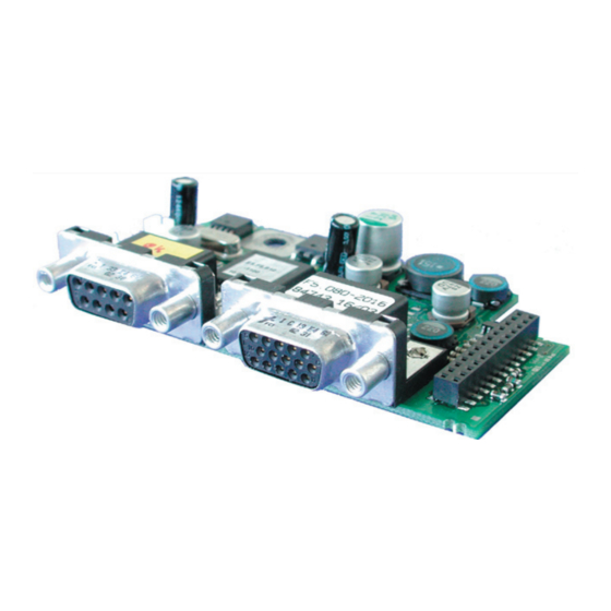
SIN/COS General Each of the interface cards delivered by KEB include two interfaces. As there are numerous different combinations available each interface will be described by means of separate in- structions. The instruction comprises the installation of the interface card, the connection as well as the start-up of a suitable encoder. -
Page 7: Mechanical Installation
SIN/COS at Channel 1 Mechanical installation All kind of works on the inverter may be carried out by authorized personnel in accordance with the EMC and safety rules only. • Switch inverter de-energized and await capacitor discharge time • Pull off operator •... -
Page 8: Channel 1
SIN/COS at Channel 1 Channel 1 3.2.1 Specifications Socket SUB-D15 Interface type SIN/COS Inputs / tracks 1 Vss typical (0.6…1.2) Limiting frequency 200 kHz Increments per re- 1…2048 inc (recommendation 1024 inc for speed upto 4500 rpm volution Input resistance 120 Ω... -
Page 9: Analog Input Signals
SIN/COS at Channel 1 The output signals of tracks A and B are dependent on the encoder line number. If the en- coder line number, adjusted in parameter Ec.01, is not correspond with the actual encoder line number, an error will be triggered immediately after revolution of the rotor axis. The zero track will permanently be compared with the position. In case a difference occurs the position will be corrected with a ramp time after a filter. In addition the position value of the absolute track (C and D) will be compared with the position any 30 ms. -
Page 10: Encoder Monitoring
SIN/COS at Channel 1 3.2.3.2 Encoder monitoring Parameter Enter prog. Ec.42 Encoder alarm mode The encoder monitoring is a software function and dependent on the encoder type. The absolute track is monitored approx. all 30 ms and the incremental track is monitored ap- prox. -
Page 11: Connection Of The Encoder
SIN/COS at Channel 1 3.2.4 Connection of the encoder 3.2.4.1 Encoder cabel at SUB-D15 • Encoder cable double-shielded and twisted in pairs • Connect exterior shielding at both ends to PE/GND • Connect interior shielding at one side to COM •... -
Page 12: Encoder Cable
: see encoder description Supply voltage U: 5.2 V minimum input voltage U : see encoder description KEB encoder cable resistance R: 0.036 Ω/m at 0.5 mm² 3.2.7 Tested encoders The following encoder can be used dependent on the interface and the control: Manufacturer Type... -
Page 13: Start-Up
SIN/COS at Channel 1 Start-up After installation or exchange of an encoder interface some adjustments of the inverter/ servo software have to be done before operation: • Switch on inverter • Select application mode • When using synchronous motors set ud.2 to F5-S •... - Page 14 Encoder signals are outside the specification (message from encoder) Encoder has internal defect (message from encoder) Encoder will be formatted. When writing an encoder with memory structures different from the KEB-definition, their memories will be re-organized in such a manner that they can be written. This procedure can take some seconds, depen- ding on the respective memory structure. New value detected, because an another encoder is attached.
- Page 15 Notices GB -15...
- Page 16 Headquarter KEB Automation KG KEB Antriebstechnik GmbH • Getriebemotorenwerk Südstraße 38 • D - 32683 Barntrup Wildbacher Straße 5 • D - 08289 Schneeberg Telefon +49 5263 401-0 • Telefax 401-116 Telefon +49 3772 67-0 • Telefax 67-281 Internet: www.keb.de • E-Mail: info@keb.de Internet: www.keb-drive.de •...
Need help?
Do you have a question about the ACOMBIVERT F5 X3A and is the answer not in the manual?
Questions and answers